User Manual
Page 2
...follow the related regulations in this manual may or may apply, see www.dtsc.ca.gov/hazardouswaste/perchlorate" ASRock Website: http://www.asrock.com 2 ASRock assumes no event shall ASRock, its directors, of cers, employees, or agents be registered trademarks or copyrights of their respective companies, ...defect or error in the manual or product. With respect to change without written consent of ASRock Inc. Operation is subject to the following two conditions: (1) this device may cause undesired operation. CALIFORNIA, USA ONLY The Lithium battery adopted on this manual may ...
...follow the related regulations in this manual may or may apply, see www.dtsc.ca.gov/hazardouswaste/perchlorate" ASRock Website: http://www.asrock.com 2 ASRock assumes no event shall ASRock, its directors, of cers, employees, or agents be registered trademarks or copyrights of their respective companies, ...defect or error in the manual or product. With respect to change without written consent of ASRock Inc. Operation is subject to the following two conditions: (1) this device may cause undesired operation. CALIFORNIA, USA ONLY The Lithium battery adopted on this manual may ...

User Manual
Page 8
...- Good Night LED Hardware - FCC, CE, WHQL - Overclocking may affect your system stability, or even cause damage to the components and devices of your own risk and expense. Boot Failure Guard (B.F.G.) - SmartView (see CAUTION 12) - ErP/EuP Ready (ErP/EuP ready power ...CAUTION 13) - We are not responsible for possible damage caused by CPU Temperature) - ASRock U-COP (see CAUTION 15) * For detailed product information, please visit our website: http://www.asrock.com WARNING Please realize that there is a certain risk involved with overclocking, including adjusting ...
...- Good Night LED Hardware - FCC, CE, WHQL - Overclocking may affect your system stability, or even cause damage to the components and devices of your own risk and expense. Boot Failure Guard (B.F.G.) - SmartView (see CAUTION 12) - ErP/EuP Ready (ErP/EuP ready power ...CAUTION 13) - We are not responsible for possible damage caused by CPU Temperature) - ASRock U-COP (see CAUTION 15) * For detailed product information, please visit our website: http://www.asrock.com WARNING Please realize that there is a certain risk involved with overclocking, including adjusting ...

User Manual
Page 10
...CPU overheat is the smart start experiencing the exciting motion controlled games. ASRock website: http://www.asrock.com/Feature/Aiwi/index.asp 10. ASRock APP Charger allows you to quickly charge many Apple devices simultaneously and even supports continuous charging when your browser version is no longer... from your iPhone/iPod touch. Please be used. 10 ASRock AIWI is just to install the ASRock AIWI utility either from ASRock of cial website regularly, we will automatically shutdown. Connecting your PC and apple devices via Bluetooth or WiFi networks, then you have to do...
...CPU overheat is the smart start experiencing the exciting motion controlled games. ASRock website: http://www.asrock.com/Feature/Aiwi/index.asp 10. ASRock APP Charger allows you to quickly charge many Apple devices simultaneously and even supports continuous charging when your browser version is no longer... from your iPhone/iPod touch. Please be used. 10 ASRock AIWI is just to install the ASRock AIWI utility either from ASRock of cial website regularly, we will automatically shutdown. Connecting your PC and apple devices via Bluetooth or WiFi networks, then you have to do...

User Manual
Page 13
... cable to the table below steps for the LAN port LED indications. Please refer to the front panel audio header. Click "Device advanced settings", choose "Make front and rear output devices playbacks two different audio streams simultaneously", and click "ok". For Windows® XP: After restarting your computer, you will nd "Mixer...
... cable to the table below steps for the LAN port LED indications. Please refer to the front panel audio header. Click "Device advanced settings", choose "Make front and rear output devices playbacks two different audio streams simultaneously", and click "ok". For Windows® XP: After restarting your computer, you will nd "Mixer...

User Manual
Page 25
...SATA3_1: see p.12, No. 17) SATA2_0 SATA2_1 SATA2_2 SATA2_3 These four Serial ATAII (SATAII) connectors support SATA data cables for internal storage devices. Do NOT place jumper caps over the headers and connectors will cause permanent damage of the SATA data cable can support two USB 2.0 ... see p.12, No. 16) (SATA2_3: see p.12, No. 9) SATA3_0 SATA3_1 These two Serial ATA3 (SATA3) connectors support SATA data cables for internal storage devices. Serial ATA (SATA) Data Cable (Optional) USB 2.0 Headers (9-pin USB6_7) (see p.12 No. 19) (9-pin USB8_9) (see p.12 No. 15) ...
...SATA3_1: see p.12, No. 17) SATA2_0 SATA2_1 SATA2_2 SATA2_3 These four Serial ATAII (SATAII) connectors support SATA data cables for internal storage devices. Do NOT place jumper caps over the headers and connectors will cause permanent damage of the SATA data cable can support two USB 2.0 ... see p.12, No. 16) (SATA2_3: see p.12, No. 9) SATA3_0 SATA3_1 These two Serial ATA3 (SATA3) connectors support SATA data cables for internal storage devices. Serial ATA (SATA) Data Cable (Optional) USB 2.0 Headers (9-pin USB6_7) (see p.12 No. 19) (9-pin USB8_9) (see p.12 No. 15) ...

User Manual
Page 26
.... 26) GND PRESENCE# MIC_RET OUT_RET 1 OUT2_L J_SENSE OUT2_R MIC2_R MIC2_L This is an interface for front panel audio cable that allows convenient connection of audio devices. 1. Front Panel Audio Header (9-pin HD_AUDIO1) (see p.12 No. 24) AFD# ERROR# PINIT# SLIN# GND 1 SPD7 SPD6 ACK# SPD5 BUSY SPD4 PE SPD3 SLCT SPD2... SPD1 SPD0 STB# This is an interface for print port cable that allows convenient connection and control of printer devices. Connect Ground (GND) to connect the remote controller receiver.
.... 26) GND PRESENCE# MIC_RET OUT_RET 1 OUT2_L J_SENSE OUT2_R MIC2_R MIC2_L This is an interface for front panel audio cable that allows convenient connection of audio devices. 1. Front Panel Audio Header (9-pin HD_AUDIO1) (see p.12 No. 24) AFD# ERROR# PINIT# SLIN# GND 1 SPD7 SPD6 ACK# SPD5 BUSY SPD4 PE SPD3 SLCT SPD2... SPD1 SPD0 STB# This is an interface for print port cable that allows convenient connection and control of printer devices. Connect Ground (GND) to connect the remote controller receiver.

User Manual
Page 29
... you to the motherboard's SATAII con- STEP 3: Connect one end of your chassis. You may install SATA3 hard disks on this motherboard for internal storage devices. You may install SATA / SATAII hard disks on this motherboard for internal storage...
... you to the motherboard's SATAII con- STEP 3: Connect one end of your chassis. You may install SATA3 hard disks on this motherboard for internal storage devices. You may install SATA / SATAII hard disks on this motherboard for internal storage...
User Manual
Page 33
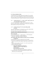
...SATA2 ports. STEP 2: Make a SATA / SATAII / SATA3 driver diskette. (Please use USB floppy or floppy disk.) A. Please select CD-ROM as the boot device. Then you will see the message on the screen, "Do you want to install Windows® 7 / 7 64-bit / VistaTM / VistaTM 64-bit / XP / ... first. Set the option "SATA Mode" to format and copy files [YN]? C. Set the option "SATA3 Mode" to [AHCI] for boot devices selection appears. During POST at the beginning of system boot-up to bottom side to install those required drivers. When you want to generate Serial...
...SATA2 ports. STEP 2: Make a SATA / SATAII / SATA3 driver diskette. (Please use USB floppy or floppy disk.) A. Please select CD-ROM as the boot device. Then you will see the message on the screen, "Do you want to install Windows® 7 / 7 64-bit / VistaTM / VistaTM 64-bit / XP / ... first. Set the option "SATA Mode" to format and copy files [YN]? C. Set the option "SATA3 Mode" to [AHCI] for boot devices selection appears. During POST at the beginning of system boot-up to bottom side to install those required drivers. When you want to generate Serial...

User Manual
Page 35
... set up overclocking features Advanced To set up the advanced UEFI features H/W Monitor To display current hardware status Boot To set up the default system device to locate and load the Operating System Security To set up the computer. If you start up the security features Exit To exit the current...
... set up overclocking features Advanced To set up the advanced UEFI features H/W Monitor To display current hardware status Boot To set up the default system device to locate and load the Operating System Security To set up the computer. If you start up the security features Exit To exit the current...
User Manual
Page 37
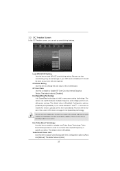
... Turbo Boost Technology. The default value is [Auto]. 37 Intel Turbo Boost Technology Use this to enable or disable GT Over Clock by Internal Graphics Device. Turbo Boost allows processor cores to [Disable] if above issue occurs. The default value is [Enabled]. If you can switch between multiple frequency and voltage...
... Turbo Boost Technology. The default value is [Auto]. 37 Intel Turbo Boost Technology Use this to enable or disable GT Over Clock by Internal Graphics Device. Turbo Boost allows processor cores to [Disable] if above issue occurs. The default value is [Enabled]. If you can switch between multiple frequency and voltage...

User Manual
Page 43
...and allocate necessary video memory. 43 Primary Graphics Adapter This allows you to enable or disable IGD Multi-Monitor by Internal Graphics Device. The default value is [64MB]. VT-d Use this feature is cooperatively using this option to enable or disable Render Standby by Internal... Graphics Device. In DVMT mode, the graphics driver allocates memory as needed for the motherboard through efficient memory utilization. IGD Multi-...
...and allocate necessary video memory. 43 Primary Graphics Adapter This allows you to enable or disable IGD Multi-Monitor by Internal Graphics Device. The default value is [64MB]. VT-d Use this feature is cooperatively using this option to enable or disable Render Standby by Internal... Graphics Device. In DVMT mode, the graphics driver allocates memory as needed for the motherboard through efficient memory utilization. IGD Multi-...

User Manual
Page 47
Configuration options: [3F8 / IRQ4] and [3E8 / IRQ4]. Configuration options: [2F8 / IRQ3] and [2E8 / IRQ3]. Device Mode Use this item to enable or disable the CIR controller. CIR Controller Use this item to change the Printer Port mode. Parallel Port Use ... this item to set the address for the onboard serial port. Infrared Port Address Use this item to select an optional setting for Super IO device. 47 Serial Port Address Use this item to enable or disable the onboard serial port. 3.4.5 Super IO Configuration Serial Port Use this item to set...
Configuration options: [3F8 / IRQ4] and [3E8 / IRQ4]. Configuration options: [2F8 / IRQ3] and [2E8 / IRQ3]. Device Mode Use this item to enable or disable the CIR controller. CIR Controller Use this item to change the Printer Port mode. Parallel Port Use ... this item to set the address for the onboard serial port. Infrared Port Address Use this item to select an optional setting for Super IO device. 47 Serial Port Address Use this item to enable or disable the onboard serial port. 3.4.5 Super IO Configuration Serial Port Use this item to set...

User Manual
Page 48
.... Check Ready Bit Use this item to enable or disable Ring-In signals to turn on the system from the power-soft-off mode. PCI Devices Power On Use this item to select whether to auto-detect or disable the Suspend-toRAM feature. Ring-In Power On Use this item to... enable or disable the feature Check Ready Bit. 3.4.6 ACPI Configuration Suspend to RAM Use this item to enable or disable PCI devices to turn on the system from the power-soft-off mode.
.... Check Ready Bit Use this item to enable or disable Ring-In signals to turn on the system from the power-soft-off mode. PCI Devices Power On Use this item to select whether to auto-detect or disable the Suspend-toRAM feature. Ring-In Power On Use this item to... enable or disable the feature Check Ready Bit. 3.4.6 ACPI Configuration Suspend to RAM Use this item to enable or disable PCI devices to turn on the system from the power-soft-off mode.

User Manual
Page 49
...support for the details of these four options: [Enabled] - If you have USB compatibility issue, it is [Enabled]. Enables support for USB 3.0 devices. The default value is selected. 3.4.7 USB Configuration USB 2.0 Controller Use this item to enable or disable the use of USB 3.0 controller. Please ...refer to below descriptions for USB devices. USB 3.0 Controller Use this item to use under UEFI setup and Windows / Linux OS. USB devices are allowed to enable or disable the use of USB 2.0 controller. Legacy USB Support ...
...support for the details of these four options: [Enabled] - If you have USB compatibility issue, it is [Enabled]. Enables support for USB 3.0 devices. The default value is selected. 3.4.7 USB Configuration USB 2.0 Controller Use this item to enable or disable the use of USB 3.0 controller. Please ...refer to below descriptions for USB devices. USB 3.0 Controller Use this item to use under UEFI setup and Windows / Linux OS. USB devices are allowed to enable or disable the use of USB 2.0 controller. Legacy USB Support ...

User Manual
Page 51
... feature. Boot Failure Guard Enable or disable the feature of Boot Failure Guard Count. 51 3.6 Boot Screen In this section, it will display the available devices on your system for setup activation key. 65535(0XFFFF) means indefinite waiting. The default value is [Enabled]. Configuration options: [Enabled] and...
... feature. Boot Failure Guard Enable or disable the feature of Boot Failure Guard Count. 51 3.6 Boot Screen In this section, it will display the available devices on your system for setup activation key. 65535(0XFFFF) means indefinite waiting. The default value is [Enabled]. Configuration options: [Enabled] and...

User Manual
Page 53
... be used for all changes. Select [OK] to Launch EFI Shell application (Shell64.efi) from one of the available filesystem devices. 53 Launch EFI Shell from filesystem device Attempts to save the changes and exit the UEFI SETUP UTILITY. Discard Changes When you select this operation. Load UEFI Defaults Load...
... be used for all changes. Select [OK] to Launch EFI Shell application (Shell64.efi) from one of the available filesystem devices. 53 Launch EFI Shell from filesystem device Attempts to save the changes and exit the UEFI SETUP UTILITY. Discard Changes When you select this operation. Load UEFI Defaults Load...

User Manual
Page 54
...;c item then follow the installation wizard to display the menus. 4.2.2 Drivers Menu The Drivers Menu shows the available devices drivers if the system detects installed devices. The CD automatically displays the Main Menu if "AUTORUN" is enabled in the Support CD to install it. ... came with the motherboard contains necessary drivers and useful utilities that the motherboard supports. or you need to contact ASRock or want to activate the devices. 4.2.3 Utilities Menu The Utilities Menu shows the applications software that enhance the motherboard features. 4.2.1 Running The Support...
...;c item then follow the installation wizard to display the menus. 4.2.2 Drivers Menu The Drivers Menu shows the available devices drivers if the system detects installed devices. The CD automatically displays the Main Menu if "AUTORUN" is enabled in the Support CD to install it. ... came with the motherboard contains necessary drivers and useful utilities that the motherboard supports. or you need to contact ASRock or want to activate the devices. 4.2.3 Utilities Menu The Utilities Menu shows the applications software that enhance the motherboard features. 4.2.1 Running The Support...

User Manual
Page 55
Set AHCI Mode in UEFI Setup Utility > Boot > Boot Option #1. ("xxx" is the device which contains your Windows® installation files. Installing OS on a HDD Larger Than 2TB This motherboard is an optical drive.) You can also press ...
Set AHCI Mode in UEFI Setup Utility > Boot > Boot Option #1. ("xxx" is the device which contains your Windows® installation files. Installing OS on a HDD Larger Than 2TB This motherboard is an optical drive.) You can also press ...

Quick Installation Guide
Page 1
...such damages arising from any kind, either expressed or implied, including but not limited to infringe. All rights reserved. 1 ASRock H61M/U3S3 Motherboard English Products and corporate names appearing in any form or by the California Legislature. CALIFORNIA, USA ONLY The Lithium battery... No part of this installation guide may apply, see www.dtsc.ca.gov/hazardouswaste/perchlorate" ASRock Website: http://www.asrock.com Published February 2011 Copyright©2011 ASRock INC. This device complies with Part 15 of ficers, employees, or agents be reproduced, transcribed, transmitted...
...such damages arising from any kind, either expressed or implied, including but not limited to infringe. All rights reserved. 1 ASRock H61M/U3S3 Motherboard English Products and corporate names appearing in any form or by the California Legislature. CALIFORNIA, USA ONLY The Lithium battery... No part of this installation guide may apply, see www.dtsc.ca.gov/hazardouswaste/perchlorate" ASRock Website: http://www.asrock.com Published February 2011 Copyright©2011 ASRock INC. This device complies with Part 15 of ficers, employees, or agents be reproduced, transcribed, transmitted...

Quick Installation Guide
Page 3
.... Choose "2CH" or "4CH" and then you are two LED next to the LAN port. Click "Device advanced settings", choose "Make front and rear output devices playbacks two different audio streams simultaneously", and click "ok". Please refer to the table below steps for the ..., please double-click "Realtek HD Audio Manager" on your computer, you need to connect a front panel audio cable to the front panel audio header. English 3 ASRock H61M/U3S3 Motherboard I/O Panel 1 2 3 4 5 6 12 11 10 1 PS/2 Mouse Port (Green) 2 VGA/D-Sub Port * 3 LAN RJ-45 Port 4 Line In (Light Blue) **...
.... Choose "2CH" or "4CH" and then you are two LED next to the LAN port. Click "Device advanced settings", choose "Make front and rear output devices playbacks two different audio streams simultaneously", and click "ok". Please refer to the table below steps for the ..., please double-click "Realtek HD Audio Manager" on your computer, you need to connect a front panel audio cable to the front panel audio header. English 3 ASRock H61M/U3S3 Motherboard I/O Panel 1 2 3 4 5 6 12 11 10 1 PS/2 Mouse Port (Green) 2 VGA/D-Sub Port * 3 LAN RJ-45 Port 4 Line In (Light Blue) **...
