
User Manual
Page 10
... devices simultaneously and even supports continuous charging when your Apple devices, such as a game joystick to adopt three different CPU cooler types, Socket LGA 775, LGA 1155 and LGA 1156. ASRock APP Charger allows you - 9. All you desire a faster, less restricted way of cial website regularly, we will automatically shutdown. If you have...
... devices simultaneously and even supports continuous charging when your Apple devices, such as a game joystick to adopt three different CPU cooler types, Socket LGA 775, LGA 1155 and LGA 1156. ASRock APP Charger allows you - 9. All you desire a faster, less restricted way of cial website regularly, we will automatically shutdown. If you have...

User Manual
Page 12
...USB 2.0 T: USB4 Top: B: USB5 RJ-45 RoHS CMOS Battery PCI Express 2.0 Top: LINE IN Center: FRONT Bottom: MIC IN 28 LAN PHY PCIE1 H61M/U3S3 PCI1 27 26 HD_AUDIO1 1 PCI2 25 AUDIO CODEC 1 LPT1 PCIE2 COM1 1 Super I/O Dual Channel DX10.1 SATA3_0 SATA3_1 CHA_FAN1 Intel H61 32Mb BIOS SATA2_0 1 ...20 19 18 17 7 8 9 10 11 12 13 14 15 16 1 Power Fan Connector (PWR_FAN1) 15 USB 2.0 Header (USB8_9, Blue) 2 1155-Pin CPU Socket 16 SATA2 Connector (SATA2_2, Blue) 3 CPU Fan Connector (CPU_FAN1) 17 SATA2 Connector (SATA2_3, Blue) 4 ATX 12V Power Connector (ATX12V1) 18 Consumer ...
...USB 2.0 T: USB4 Top: B: USB5 RJ-45 RoHS CMOS Battery PCI Express 2.0 Top: LINE IN Center: FRONT Bottom: MIC IN 28 LAN PHY PCIE1 H61M/U3S3 PCI1 27 26 HD_AUDIO1 1 PCI2 25 AUDIO CODEC 1 LPT1 PCIE2 COM1 1 Super I/O Dual Channel DX10.1 SATA3_0 SATA3_1 CHA_FAN1 Intel H61 32Mb BIOS SATA2_0 1 ...20 19 18 17 7 8 9 10 11 12 13 14 15 16 1 Power Fan Connector (PWR_FAN1) 15 USB 2.0 Header (USB8_9, Blue) 2 1155-Pin CPU Socket 16 SATA2 Connector (SATA2_2, Blue) 3 CPU Fan Connector (CPU_FAN1) 17 SATA2 Connector (SATA2_3, Blue) 4 ATX 12V Power Connector (ATX12V1) 18 Consumer ...

User Manual
Page 15
... 135 degrees. 2.3 CPU Installation For the installation of Intel 1155-Pin CPU, please follow the steps below. Otherwise, the CPU will be placed if returning the motherboard for after service. 15 Step 2. Step 1. Step 1-3. Open the socket: Step 1-1. Rotate the load lever to fully open position ...on the hook to handle and avoid kicking off the PnP cap. 2. Load Plate Load Lever Contact Array Socket Body 1155-Pin Socket Overview Before you insert the 1155-Pin CPU into the socket if above situation is found. Remove PnP Cap (Pick and Place Cap). 1. Do not force to ...
... 135 degrees. 2.3 CPU Installation For the installation of Intel 1155-Pin CPU, please follow the steps below. Otherwise, the CPU will be placed if returning the motherboard for after service. 15 Step 2. Step 1. Step 1-3. Open the socket: Step 1-1. Rotate the load lever to fully open position ...on the hook to handle and avoid kicking off the PnP cap. 2. Load Plate Load Lever Contact Array Socket Body 1155-Pin Socket Overview Before you insert the 1155-Pin CPU into the socket if above situation is found. Remove PnP Cap (Pick and Place Cap). 1. Do not force to ...

User Manual
Page 16
.... While pressing down lightly on load plate, engage the load lever. 16 black line Step 3-2. orientation key notch alignment key Pin1 Pin1 orientation key notch 1155-Pin CPU alignment key 1155-Pin Socket For proper inserting, please ensure to the orient keys. Step 4. Step 4-2. Rotate the load plate onto the IHS. Insert the...
.... While pressing down lightly on load plate, engage the load lever. 16 black line Step 3-2. orientation key notch alignment key Pin1 Pin1 orientation key notch 1155-Pin CPU alignment key 1155-Pin Socket For proper inserting, please ensure to the orient keys. Step 4. Step 4-2. Rotate the load plate onto the IHS. Insert the...
User Manual
Page 17
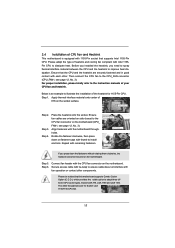
Ensure that this motherboard supports Combo Cooler Option (C.C.O.), which provides the exible option to adopt three different CPU cooler types, Socket LGA 775, LGA 1155 and LGA 1156. Step 4. Ensure fan cables are oriented on side closest to the CPU fan connector on the motherboard (... need to spray thermal interface material between the CPU and the heatsink to improve heat dissipation. Step 5. Connect fan header with 1155-Pin socket that supports Intel 1155-Pin CPU. Step 1. Step 3. The white throughholes are securely fastened and in good contact with thumb to install and lock...
Ensure that this motherboard supports Combo Cooler Option (C.C.O.), which provides the exible option to adopt three different CPU cooler types, Socket LGA 775, LGA 1155 and LGA 1156. Step 4. Ensure fan cables are oriented on side closest to the CPU fan connector on the motherboard (... need to spray thermal interface material between the CPU and the heatsink to improve heat dissipation. Step 5. Connect fan header with 1155-Pin socket that supports Intel 1155-Pin CPU. Step 1. Step 3. The white throughholes are securely fastened and in good contact with thumb to install and lock...

Quick Installation Guide
Page 2
... USB5 RJ-45 RoHS CMOS Battery PCI Express 2.0 Top: LINE IN Center: FRONT Bottom: MIC IN 28 LAN PHY PCIE1 H61M/U3S3 PCI1 27 26 HD_AUDIO1 1 PCI2 25 AUDIO CODEC 1 LPT1 PCIE2 COM1 1 Super I/O Dual Channel DX10.1 SATA3_0 SATA3_1 CHA_FAN1 Intel...9 10 11 12 13 14 15 16 1 Power Fan Connector (PWR_FAN1) 15 USB 2.0 Header (USB8_9, Blue) 2 1155-Pin CPU Socket 16 SATA2 Connector (SATA2_2, Blue) 3 CPU Fan Connector (CPU_FAN1) 17 SATA2 Connector (SATA2_3, Blue) 4 ATX 12V Power...Connector (SATA2_1, Blue) 28 PCI Express 2.0 x16 Slot (PCIE1, Blue) English 2 ASRock H61M/U3S3 Motherboard
... USB5 RJ-45 RoHS CMOS Battery PCI Express 2.0 Top: LINE IN Center: FRONT Bottom: MIC IN 28 LAN PHY PCIE1 H61M/U3S3 PCI1 27 26 HD_AUDIO1 1 PCI2 25 AUDIO CODEC 1 LPT1 PCIE2 COM1 1 Super I/O Dual Channel DX10.1 SATA3_0 SATA3_1 CHA_FAN1 Intel...9 10 11 12 13 14 15 16 1 Power Fan Connector (PWR_FAN1) 15 USB 2.0 Header (USB8_9, Blue) 2 1155-Pin CPU Socket 16 SATA2 Connector (SATA2_2, Blue) 3 CPU Fan Connector (CPU_FAN1) 17 SATA2 Connector (SATA2_3, Blue) 4 ATX 12V Power...Connector (SATA2_1, Blue) 28 PCI Express 2.0 x16 Slot (PCIE1, Blue) English 2 ASRock H61M/U3S3 Motherboard

Quick Installation Guide
Page 9
.../ SmartView/index.asp 12. To improve heat dissipation, remember to adopt three different CPU cooler types, Socket LGA 775, LGA 1155 and LGA 1156. ASRock APP Charger. ASRock website: http://www.asrock.com/Feature/AppCharger/index.asp 11. To use SmartView feature, please make sure your OS version is ...iPhone charged much quickly from App store to 40% faster than ever. ASRock motherboards are exclusively equipped with friends on the property of PC gaming operation. Please be used. 9 ASRock H61M/U3S3 Motherboard English With APP Charger driver installed, you can easily enjoy the ...
.../ SmartView/index.asp 12. To improve heat dissipation, remember to adopt three different CPU cooler types, Socket LGA 775, LGA 1155 and LGA 1156. ASRock APP Charger. ASRock website: http://www.asrock.com/Feature/AppCharger/index.asp 11. To use SmartView feature, please make sure your OS version is ...iPhone charged much quickly from App store to 40% faster than ever. ASRock motherboards are exclusively equipped with friends on the property of PC gaming operation. Please be used. 9 ASRock H61M/U3S3 Motherboard English With APP Charger driver installed, you can easily enjoy the ...

Quick Installation Guide
Page 11
... pin on the carpet or the like. Failure to do not touch the ICs. 4. Load Plate Contact Array Load Lever Socket Body 1155-Pin Socket Overview Before you handle components. 3. English 11 ASRock H61M/U3S3 Motherboard Hold components by the edges and do so may damage the motherboard. 2.1 CPU Installation For the installation of the following...
... pin on the carpet or the like. Failure to do not touch the ICs. 4. Load Plate Contact Array Load Lever Socket Body 1155-Pin Socket Overview Before you handle components. 3. English 11 ASRock H61M/U3S3 Motherboard Hold components by the edges and do so may damage the motherboard. 2.1 CPU Installation For the installation of the following...

Quick Installation Guide
Page 12
... Rotate the load lever to clear retention tab. Step 3-2. orientation key notch alignment key Pin1 Pin1 orientation key notch 1155-Pin CPU alignment key 1155-Pin Socket For proper inserting, please ensure to handle and avoid kicking off the PnP cap. 2. Orient the CPU with IHS ...(Integrated Heat Sink) up. Remove PnP Cap (Pick and Place Cap). It is recommended to use the cap tab to match the two orientation key notches of the socket. 12 ASRock H61M/U3S3...
... Rotate the load lever to clear retention tab. Step 3-2. orientation key notch alignment key Pin1 Pin1 orientation key notch 1155-Pin CPU alignment key 1155-Pin Socket For proper inserting, please ensure to handle and avoid kicking off the PnP cap. 2. Orient the CPU with IHS ...(Integrated Heat Sink) up. Remove PnP Cap (Pick and Place Cap). It is recommended to use the cap tab to match the two orientation key notches of the socket. 12 ASRock H61M/U3S3...

Quick Installation Guide
Page 13
... fasteners with remaining fasteners. Repeat with the motherboard throughholes. Secure excess cable with tie-wrap to illustrate the installation of the heatsink for Socket LGA 1155/1156 CPU fan. 13 ASRock H61M/U3S3 Motherboard English Connect fan header with fan operation or contact other components. Rotate the fastener clockwise, then press down the fasteners without...
... fasteners with remaining fasteners. Repeat with the motherboard throughholes. Secure excess cable with tie-wrap to illustrate the installation of the heatsink for Socket LGA 1155/1156 CPU fan. 13 ASRock H61M/U3S3 Motherboard English Connect fan header with fan operation or contact other components. Rotate the fastener clockwise, then press down the fasteners without...