

User Manual
Page 5
.... In case any modifications of the Support CD. www.asrock.com/support/index.asp 1.1 Package Contents ASRock H61DEL Motherboard (ATX Form Factor: 12.0-in x 6.8-in, 30.5 cm x 17.3 cm) ASRock H61DEL Quick Installation Guide ASRock H61DEL Support CD 2 x Serial ATA (SATA) Data Cables (Optional) 1 x I/O Panel Shield ASRock Reminds You...To get better performance in Windows® 7 / 7 64...
.... In case any modifications of the Support CD. www.asrock.com/support/index.asp 1.1 Package Contents ASRock H61DEL Motherboard (ATX Form Factor: 12.0-in x 6.8-in, 30.5 cm x 17.3 cm) ASRock H61DEL Quick Installation Guide ASRock H61DEL Support CD 2 x Serial ATA (SATA) Data Cables (Optional) 1 x I/O Panel Shield ASRock Reminds You...To get better performance in Windows® 7 / 7 64...

User Manual
Page 6
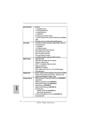
... HDMI 1.4a - PCIE x1 Gigabit LAN 10/100/1000 Mb/s - Supports Energy Efficient Ethernet 802.3az Chipset Memory Expansion Slot Graphics Audio LAN 6 ATX Form Factor: 12.0-in x 6.8-in LGA1155 Package - Supports 2nd Generation Intel® CoreTM i7 / i5 / i3 in , 30.5 cm x 17.3 cm - Max. Supports Wake-On...
... HDMI 1.4a - PCIE x1 Gigabit LAN 10/100/1000 Mb/s - Supports Energy Efficient Ethernet 802.3az Chipset Memory Expansion Slot Graphics Audio LAN 6 ATX Form Factor: 12.0-in x 6.8-in LGA1155 Package - Supports 2nd Generation Intel® CoreTM i7 / i5 / i3 in , 30.5 cm x 17.3 cm - Max. Supports Wake-On...

User Manual
Page 7
...(C.C.O.) (see CAUTION 11) - ACPI 1.1 Compliance Wake Up Events - Creative Sound Blaster X-Fi MB - ASRock U-COP (see CAUTION 12) - SMBIOS 2.3.1 Support - CPU/Chassis/Power FAN connector - 24 pin ATX power connector - 8 pin 12V power connector - Instant Boot - AMI UEFI Legal BIOS with LED (ACT/...LINK LED and SPEED LED) - ASRock APP Charger (see CAUTION 8) - HD Audio Jack: Line in/Front Speaker/Microphone -...
...(C.C.O.) (see CAUTION 11) - ACPI 1.1 Compliance Wake Up Events - Creative Sound Blaster X-Fi MB - ASRock U-COP (see CAUTION 12) - SMBIOS 2.3.1 Support - CPU/Chassis/Power FAN connector - 24 pin ATX power connector - 8 pin 12V power connector - Instant Boot - AMI UEFI Legal BIOS with LED (ACT/...LINK LED and SPEED LED) - ASRock APP Charger (see CAUTION 8) - HD Audio Jack: Line in/Front Speaker/Microphone -...

User Manual
Page 12
...64 bit, 240-pin module) DDR3_B1 (64 bit, 240-pin module) 30.5cm (12.0 in) 5 CHA_FAN1 Top: RJ-45 PWR_FAN1 27 LAN PHY 26 H61DEL PCIE1 Dual Channel PS2 Keyboard PS2 Mouse ATX12V1 USB 2.0 T: USB4 B: USB5 VGA1 HDMI1 Bottom: MIC IN Top: LINE IN HDMI 1.4a 25 24 Super ...14 13 1 2 3 4 5 6 7 8 9 10 11 12 13 14 1155-Pin CPU Socket CPU Fan Connector (CPU_FAN1) ATX 12V Power Connector (ATX12V1) 2 x 240-pin DDR3 DIMM Slots (Dual Channel: DDR3_A1, DDR3_B1, Blue) ATX Power Connector (ATXPWR1) Chassis Fan Connector (CHA_FAN1) 32Mb SPI Flash Intel H61 Chipset Clear CMOS Jumper (CLRCMOS1) Chassis...
...64 bit, 240-pin module) DDR3_B1 (64 bit, 240-pin module) 30.5cm (12.0 in) 5 CHA_FAN1 Top: RJ-45 PWR_FAN1 27 LAN PHY 26 H61DEL PCIE1 Dual Channel PS2 Keyboard PS2 Mouse ATX12V1 USB 2.0 T: USB4 B: USB5 VGA1 HDMI1 Bottom: MIC IN Top: LINE IN HDMI 1.4a 25 24 Super ...14 13 1 2 3 4 5 6 7 8 9 10 11 12 13 14 1155-Pin CPU Socket CPU Fan Connector (CPU_FAN1) ATX 12V Power Connector (ATX12V1) 2 x 240-pin DDR3 DIMM Slots (Dual Channel: DDR3_A1, DDR3_B1, Blue) ATX Power Connector (ATXPWR1) Chassis Fan Connector (CHA_FAN1) 32Mb SPI Flash Intel H61 Chipset Clear CMOS Jumper (CLRCMOS1) Chassis...

User Manual
Page 14
... of the following precautions before touching any motherboard settings. 1. Make sure to ensure that the power is switched off or the power cord is an ATX form factor (12.0" x 6.8", 30.5 x 17.3 cm) motherboard. To avoid damaging the motherboard components due to static electricity, NEVER place your chassis to unplug the power...
... of the following precautions before touching any motherboard settings. 1. Make sure to ensure that the power is switched off or the power cord is an ATX form factor (12.0" x 6.8", 30.5 x 17.3 cm) motherboard. To avoid damaging the motherboard components due to static electricity, NEVER place your chassis to unplug the power...

User Manual
Page 26
... supply along with Pin 1 and Pin 13. 12 24 20-Pin ATX Power Supply Installation 1 13 26 Pin 1-3 Connected 3-Pin Fan Installation ATX Power Connector (24-pin ATXPWR1) (see p.12 No. 5) 12 24 Please connect an ATX power supply to the CPU fan connector on this motherboard, please connect... make sure the wire assignments and the pin assign-ments are matched correctly. To use the 20-pin ATX power supply, please plug your chassis front panel module to this motherboard provides 24-pin ATX power connector, it to the ground pin. Chassis Speaker Header (4-pin SPEAKER 1) (see p.12 No....
... supply along with Pin 1 and Pin 13. 12 24 20-Pin ATX Power Supply Installation 1 13 26 Pin 1-3 Connected 3-Pin Fan Installation ATX Power Connector (24-pin ATXPWR1) (see p.12 No. 5) 12 24 Please connect an ATX power supply to the CPU fan connector on this motherboard, please connect... make sure the wire assignments and the pin assign-ments are matched correctly. To use the 20-pin ATX power supply, please plug your chassis front panel module to this motherboard provides 24-pin ATX power connector, it to the ground pin. Chassis Speaker Header (4-pin SPEAKER 1) (see p.12 No....

User Manual
Page 27
ATX 12V Power Connector (8-pin ATX12V1) (see p.12 No. 19) This COM1 header supports a serial port module. 27 To use the 4-pin ATX power supply, please plug your power supply along with Pin 1 and Pin 5. 8 5 4-Pin ATX 12V Power Supply Installation 4 1 Serial port Header (9-pin COM1) (see p.12 No. 3) 8 5 Please connect an ATX 12V power supply to this connector. 4 1 Though this motherboard provides 8-pin ATX 12V power connector, it can still work if you adopt a traditional 4-pin ATX 12V power supply.
ATX 12V Power Connector (8-pin ATX12V1) (see p.12 No. 19) This COM1 header supports a serial port module. 27 To use the 4-pin ATX power supply, please plug your power supply along with Pin 1 and Pin 5. 8 5 4-Pin ATX 12V Power Supply Installation 4 1 Serial port Header (9-pin COM1) (see p.12 No. 3) 8 5 Please connect an ATX 12V power supply to this connector. 4 1 Though this motherboard provides 8-pin ATX 12V power connector, it can still work if you adopt a traditional 4-pin ATX 12V power supply.
Quick Installation Guide
Page 2
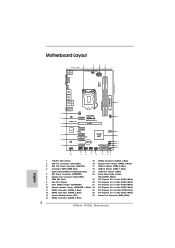
... CPU Socket 15 SATA2 Connector (SATA2_1, Blue) 2 CPU Fan Connector (CPU_FAN1) 16 System Panel Header (PANEL1, White) 3 ATX 12V Power Connector (ATX12V1) 17 USB 2.0 Header (USB8_9, Blue) 4 2 x 240-pin DDR3 DIMM Slots 18 USB 2.0... Header (USB6_7, Blue) (Dual Channel: DDR3_A1, DDR3_B1, Blue) 19 COM Port Header (COM1) 5 ATX Power Connector (ATXPWR1) 20 Front Panel Audio Header 6 Chassis Fan Connector (CHA_FAN1) (HD_AUDIO1, White) 7 32Mb SPI Flash 21 PCI Express... Fan Connector (PWR_FAN1) 14 SATA2 Connector (SATA2_3, Blue) 2 ASRock H61DEL Motherboard English
... CPU Socket 15 SATA2 Connector (SATA2_1, Blue) 2 CPU Fan Connector (CPU_FAN1) 16 System Panel Header (PANEL1, White) 3 ATX 12V Power Connector (ATX12V1) 17 USB 2.0 Header (USB8_9, Blue) 4 2 x 240-pin DDR3 DIMM Slots 18 USB 2.0... Header (USB6_7, Blue) (Dual Channel: DDR3_A1, DDR3_B1, Blue) 19 COM Port Header (COM1) 5 ATX Power Connector (ATXPWR1) 20 Front Panel Audio Header 6 Chassis Fan Connector (CHA_FAN1) (HD_AUDIO1, White) 7 32Mb SPI Flash 21 PCI Express... Fan Connector (PWR_FAN1) 14 SATA2 Connector (SATA2_3, Blue) 2 ASRock H61DEL Motherboard English
Quick Installation Guide
Page 4
...Package Contents ASRock H61DEL Motherboard (ATX Form Factor: 12.0-in x 6.8-in Storage Configuration to this manual occur, the updated version will be updated, the content of this motherboard, please visit our website for purchasing ASRock H61DEL motherboard, a reliable motherboard produced under ASRock's consistently ...64257;cations of this manual will be found in the user manual presented in our support CD for details. 4 ASRock H61DEL Motherboard English Introduction Thank you for specific information about the model you require technical support related to AHCI ...
...Package Contents ASRock H61DEL Motherboard (ATX Form Factor: 12.0-in x 6.8-in Storage Configuration to this manual occur, the updated version will be updated, the content of this motherboard, please visit our website for purchasing ASRock H61DEL motherboard, a reliable motherboard produced under ASRock's consistently ...64257;cations of this manual will be found in the user manual presented in our support CD for details. 4 ASRock H61DEL Motherboard English Introduction Thank you for specific information about the model you require technical support related to AHCI ...

Quick Installation Guide
Page 5
... Express 2.0 x16 slot (blue @ x16 mode) - 5 x PCI Express 2.0 x1 slots - resolution up to 1920x1200 @ 60Hz - Supports LAN Cable Detection - ATX Form Factor: 12.0-in x 6.8-in LGA1155 Package - Supports Intel® Turbo Boost 2.0 Technology - Supports K-Series unlocked CPU - Max. Realtek RTL8111E - Max.... 2) - 2 x DDR3 DIMM slots - resolution up to 2048x1536 @ 75Hz - Supports Energy Efficient Ethernet 802.3az English 5 ASRock H61DEL Motherboard Solid Capacitor for CPU power - PCIE x1 Gigabit LAN 10/100/1000 Mb/s - Supports Auto Lip Sync, Deep Color (12bpc), ...
... Express 2.0 x16 slot (blue @ x16 mode) - 5 x PCI Express 2.0 x1 slots - resolution up to 1920x1200 @ 60Hz - Supports LAN Cable Detection - ATX Form Factor: 12.0-in x 6.8-in LGA1155 Package - Supports Intel® Turbo Boost 2.0 Technology - Supports K-Series unlocked CPU - Max. Realtek RTL8111E - Max.... 2) - 2 x DDR3 DIMM slots - resolution up to 2048x1536 @ 75Hz - Supports Energy Efficient Ethernet 802.3az English 5 ASRock H61DEL Motherboard Solid Capacitor for CPU power - PCIE x1 Gigabit LAN 10/100/1000 Mb/s - Supports Auto Lip Sync, Deep Color (12bpc), ...
Quick Installation Guide
Page 6
... Night LED English 6 ASRock H61DEL Motherboard ACPI 1.1 Compliance Wake Up Events - Creative Sound Blaster X-Fi MB - ASRock XFast USB (see CAUTION 11) - ASRock Extreme Tuning Utility (AXTU) (see CAUTION 7) - ASRock Instant Flash (see CAUTION 6) - Drivers, Utilities, AntiVirus Software (Trial Version), ASRock Software Suite (CyberLink DVD...GUI support - AMI UEFI Legal BIOS with LED (ACT/LINK LED and SPEED LED) - CPU/Chassis/Power FAN connector - 24 pin ATX power connector - 8 pin 12V power connector - HD Audio Jack: Line in/Front Speaker/Microphone - 4 x SATA2 3.0 Gb/s connectors...
... Night LED English 6 ASRock H61DEL Motherboard ACPI 1.1 Compliance Wake Up Events - Creative Sound Blaster X-Fi MB - ASRock XFast USB (see CAUTION 11) - ASRock Extreme Tuning Utility (AXTU) (see CAUTION 7) - ASRock Instant Flash (see CAUTION 6) - Drivers, Utilities, AntiVirus Software (Trial Version), ASRock Software Suite (CyberLink DVD...GUI support - AMI UEFI Legal BIOS with LED (ACT/LINK LED and SPEED LED) - CPU/Chassis/Power FAN connector - 24 pin ATX power connector - 8 pin 12V power connector - HD Audio Jack: Line in/Front Speaker/Microphone - 4 x SATA2 3.0 Gb/s connectors...

Quick Installation Guide
Page 21
... wire assignments and the pin assign-ments are matched correctly. English 20-Pin ATX Power Supply Installation 1 13 21 ASRock H61DEL Motherboard The front panel design may differ by chassis. Pin 1-3 Connected 3-Pin Fan Installation ATX Power Connector (24-pin ATXPWR1) (see p.2 No. 10) Please connect the... Pin 1-3. Chassis Speaker Header (4-pin SPEAKER 1) (see p.2 No. 5) 12 24 Please connect an ATX power supply to this connector. 1 13 Though this motherboard provides 24-pin ATX power connector, 12 24 it to the CPU fan connector on this header. To use the 20-pin...
... wire assignments and the pin assign-ments are matched correctly. English 20-Pin ATX Power Supply Installation 1 13 21 ASRock H61DEL Motherboard The front panel design may differ by chassis. Pin 1-3 Connected 3-Pin Fan Installation ATX Power Connector (24-pin ATXPWR1) (see p.2 No. 10) Please connect the... Pin 1-3. Chassis Speaker Header (4-pin SPEAKER 1) (see p.2 No. 5) 12 24 Please connect an ATX power supply to this connector. 1 13 Though this motherboard provides 24-pin ATX power connector, 12 24 it to the CPU fan connector on this header. To use the 20-pin...

Quick Installation Guide
Page 22
ATX 12V Power Connector (8-pin ATX12V1) (see p.2 No. 19) This COM1 header supports a serial port module. Though this connector. English 22 ASRock H61DEL Motherboard To use the 4-pin ATX power supply, please plug your power supply along with Pin 1 and Pin 5. 8 5 4-Pin ATX 12V Power Supply Installation 4 1 Serial port Header (9-pin COM1) (see p.2 No. 3) 8 5 4 1 Please connect an ATX 12V power supply to this motherboard provides 8-pin ATX 12V power connector, it can still work if you adopt a traditional 4-pin ATX 12V power supply.
ATX 12V Power Connector (8-pin ATX12V1) (see p.2 No. 19) This COM1 header supports a serial port module. Though this connector. English 22 ASRock H61DEL Motherboard To use the 4-pin ATX power supply, please plug your power supply along with Pin 1 and Pin 5. 8 5 4-Pin ATX 12V Power Supply Installation 4 1 Serial port Header (9-pin COM1) (see p.2 No. 3) 8 5 4 1 Please connect an ATX 12V power supply to this motherboard provides 8-pin ATX 12V power connector, it can still work if you adopt a traditional 4-pin ATX 12V power supply.

Quick Installation Guide
Page 112
日本語 1.2 仕様 CPU LAN I /O Panel - ATX 12.0-in x 6.8-in LGA1155 パッ Intel® Turbo 2.0 K CPU 1 Intel® H61 DDR3 ( 注意 2 DDR3 DIMM x 2 - PS/2 x 1 ASRock H61DEL Motherboard CPU 2 世代の Intel® CoreTM i7 / i5 / i3 in , 30.5 cm x 17.3 cm - PCIE x1 Gigabit LAN 10/100/1000 Mb...
日本語 1.2 仕様 CPU LAN I /O Panel - ATX 12.0-in x 6.8-in LGA1155 パッ Intel® Turbo 2.0 K CPU 1 Intel® H61 DDR3 ( 注意 2 DDR3 DIMM x 2 - PS/2 x 1 ASRock H61DEL Motherboard CPU 2 世代の Intel® CoreTM i7 / i5 / i3 in , 30.5 cm x 17.3 cm - PCIE x1 Gigabit LAN 10/100/1000 Mb...

Quick Installation Guide
Page 120
... PWR_FAN_SPEED +12V GND CPU 4 ピン CPU_FAN1 2 を参照 FAN_SPEED_CONTROL CPU_FAN_SPEED +12V GND CPU 1 2 3 4 4 ピン CPU 3 ピン CPU 3 ピン CPU CPU 1-3 1-3 3 ATX 24 ピン ATXPWR1 5 を参照 12 24 ATX 1 13 日本語 120 ASRock H61DEL Motherboard
... PWR_FAN_SPEED +12V GND CPU 4 ピン CPU_FAN1 2 を参照 FAN_SPEED_CONTROL CPU_FAN_SPEED +12V GND CPU 1 2 3 4 4 ピン CPU 3 ピン CPU 3 ピン CPU CPU 1-3 1-3 3 ATX 24 ピン ATXPWR1 5 を参照 12 24 ATX 1 13 日本語 120 ASRock H61DEL Motherboard

Quick Installation Guide
Page 121
24 ピン ATX 従来の 20 ピン ATX 12 24 20 ピン ATX 1 13 ATX 12V 8 ピン ATX12V1 3 を参照 20 ピン ATX 1 13 8 5 4 1 CPU に Vcore ATX 12V 8-pin ATX 12V 4-pin ATX 12V 4-pin ATX Pin 1 と Pin 5 8 5 4-Pin ATX 12V 4 1 9 ピン COM1 19 を参照 この COM1 日本語 121 ASRock H61DEL Motherboard
24 ピン ATX 従来の 20 ピン ATX 12 24 20 ピン ATX 1 13 ATX 12V 8 ピン ATX12V1 3 を参照 20 ピン ATX 1 13 8 5 4 1 CPU に Vcore ATX 12V 8-pin ATX 12V 4-pin ATX 12V 4-pin ATX Pin 1 と Pin 5 8 5 4-Pin ATX 12V 4 1 9 ピン COM1 19 を参照 この COM1 日本語 121 ASRock H61DEL Motherboard

Quick Installation Guide
Page 124
... Panel I /O 界面 - 1 個 PS/2 1 個 PS/2 1 個 VGA/D-Sub 接口 - 1 個 HDMI 接口 - 6 USB 2.0 接口 簡體中文 124 ASRock H61DEL Motherboard ATX 規格 : 12.0 英吋 X 6.8 英吋 , 30.5 厘米 X 17.3 厘米 - Pixel Shader 4.1 技術,DirectX 10.1 1759MB 4) - 雙 VGA HDMI...
... Panel I /O 界面 - 1 個 PS/2 1 個 PS/2 1 個 VGA/D-Sub 接口 - 1 個 HDMI 接口 - 6 USB 2.0 接口 簡體中文 124 ASRock H61DEL Motherboard ATX 規格 : 12.0 英吋 X 6.8 英吋 , 30.5 厘米 X 17.3 厘米 - Pixel Shader 4.1 技術,DirectX 10.1 1759MB 4) - 雙 VGA HDMI...

Quick Installation Guide
Page 125
... LED) 4 x SATA2 3.0Gb/s NCQ, AHCI 能 - 1 x 1 x CPU 24 針 ATX 8 針 12V 2 x USB 2.0 4 USB 2.0 接口 ) - 32Mb AMI BIOS - SmartView 9 XFast USB 10) - Boot Failure Guard (B.F.G C.C.O 12 CPU CPU CPU CPU CPU 12V, +5V, +3.3V 簡體中文 125 ASRock H61DEL Motherboard ACPI 1.1 jumperfree IGPU、DRAM、PCH、CPU...
... LED) 4 x SATA2 3.0Gb/s NCQ, AHCI 能 - 1 x 1 x CPU 24 針 ATX 8 針 12V 2 x USB 2.0 4 USB 2.0 接口 ) - 32Mb AMI BIOS - SmartView 9 XFast USB 10) - Boot Failure Guard (B.F.G C.C.O 12 CPU CPU CPU CPU CPU 12V, +5V, +3.3V 簡體中文 125 ASRock H61DEL Motherboard ACPI 1.1 jumperfree IGPU、DRAM、PCH、CPU...

Quick Installation Guide
Page 131
... ATX 12 24 傳統的 20-pin ATX 20-pin ATX Pin 1 和 Pin 13 20-Pin ATX 1 13 ATX 12V 接頭 (8 針 ATX12V1) ( 見第 2 頁第 3 項 ) 8 5 4 1 ATX 12V 8-pin ATX 12V 4-pin ATX 12V 4-pin ATX 12V Pin 1 和 Pin 5 插上電 源接頭。 8 5 4-Pin ATX 12V 4 1 簡體中文 131 ASRock H61DEL...
... ATX 12 24 傳統的 20-pin ATX 20-pin ATX Pin 1 和 Pin 13 20-Pin ATX 1 13 ATX 12V 接頭 (8 針 ATX12V1) ( 見第 2 頁第 3 項 ) 8 5 4 1 ATX 12V 8-pin ATX 12V 4-pin ATX 12V 4-pin ATX 12V Pin 1 和 Pin 5 插上電 源接頭。 8 5 4-Pin ATX 12V 4 1 簡體中文 131 ASRock H61DEL...

Quick Installation Guide
Page 135
ATX 規格 : 12.0 英吋 x 6.8 英吋 , 30.5 公分 x 17.3 公分 - Intel® HD Graphics 2000/3000 - Intel® H61 DDR3 2) - 2 個 ...; - 1.2 Rear Panel I /O 界面 - 1 個 PS/2 1 個 PS/2 1 個 VGA/D-Sub 接口 - 1 個 HDMI 接口 - 6 USB 2.0 接口 繁體中文 135 ASRock H61DEL Motherboard
ATX 規格 : 12.0 英吋 x 6.8 英吋 , 30.5 公分 x 17.3 公分 - Intel® HD Graphics 2000/3000 - Intel® H61 DDR3 2) - 2 個 ...; - 1.2 Rear Panel I /O 界面 - 1 個 PS/2 1 個 PS/2 1 個 VGA/D-Sub 接口 - 1 個 HDMI 接口 - 6 USB 2.0 接口 繁體中文 135 ASRock H61DEL Motherboard