User Manual
Page 11
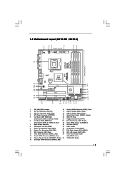
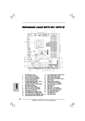
... 22 Print Port Header (LPT1, Purple) (Dual Channel: DDR3_A1, DDR3_B1; Red) (HD_AUDIO1, Lime) 14 Chassis Speaker Header (SPEAKER 1, Purple) 30 775-Pin CPU Socket 15 Secondary SATAII Connector (SATAII_2; 1.3 Motherboard Layout (G41C-GS / G41C-S) 1 23 4 19.8cm (7.8 in) 1 PS2_USB_PWR1 ATX12V2 CPU_FAN1 56 PS2 Mouse PS2 Keyboard COM1 24.4cm (9.6 in) DDR3_B1 (64 bit, 240...
... 22 Print Port Header (LPT1, Purple) (Dual Channel: DDR3_A1, DDR3_B1; Red) (HD_AUDIO1, Lime) 14 Chassis Speaker Header (SPEAKER 1, Purple) 30 775-Pin CPU Socket 15 Secondary SATAII Connector (SATAII_2; 1.3 Motherboard Layout (G41C-GS / G41C-S) 1 23 4 19.8cm (7.8 in) 1 PS2_USB_PWR1 ATX12V2 CPU_FAN1 56 PS2 Mouse PS2 Keyboard COM1 24.4cm (9.6 in) DDR3_B1 (64 bit, 240...

User Manual
Page 15
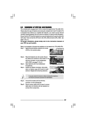
... Pin1 and the two orientation key notches. Pin1 orientation key notch orientation key notch Pin1 alignment key alignment key 775-LAND CPU 775-Pin Socket 15 Step 1-2. Step 1. DLifitsLeevnergUapgtoin9g0° the lever by the edges where are marked with IHS (Integrated Heat...black line Step 2-2. Step 1-3. 2.3 CPU Installation For the installation of Intel 775-LAND CPU, please follow the steps below. 775-Pin Socket Overview Before you insert the 775-LAND CPU into the socket if above situation is any bent pin on the ShoockoetkMatrokedcCleoranerr retention tab. Do not...
... Pin1 and the two orientation key notches. Pin1 orientation key notch orientation key notch Pin1 alignment key alignment key 775-LAND CPU 775-Pin Socket 15 Step 1-2. Step 1. DLifitsLeevnergUapgtoin9g0° the lever by the edges where are marked with IHS (Integrated Heat...black line Step 2-2. Step 1-3. 2.3 CPU Installation For the installation of Intel 775-LAND CPU, please follow the steps below. 775-Pin Socket Overview Before you insert the 775-LAND CPU into the socket if above situation is any bent pin on the ShoockoetkMatrokedcCleoranerr retention tab. Do not...
User Manual
Page 17
... and heatsink. For proper installation, please kindly refer to dissipate heat. Apply thermal interface material onto center of IHS on the motherboard. Step 3. Repeat with 775-Pin socket that the CPU and the heatsink are oriented on the motherboard (CPU_FAN1, see page 11, No. 3). Step 5. 2.4 Installation of CPU Fan and Heatsink This...
... and heatsink. For proper installation, please kindly refer to dissipate heat. Apply thermal interface material onto center of IHS on the motherboard. Step 3. Repeat with 775-Pin socket that the CPU and the heatsink are oriented on the motherboard (CPU_FAN1, see page 11, No. 3). Step 5. 2.4 Installation of CPU Fan and Heatsink This...
Quick Installation Guide
Page 2
... Chassis Fan Connector (CHA_FAN1) 27 EUP Audio Jumper (EUP_AUDIO1) 11 IDE1 Connector (IDE1, Blue) 28 EUP LAN Jumper (EUP_LAN1) 12 Third SATAII Connector (SATAII_3; Red) 2 ASRock G41C-GS / G41C-S Motherboard Red) 2 ATX 12V Connector (ATX12V2) 17 USB 2.0 Header (USB6_7, Blue) 3 CPU Fan Connector (CPU_FAN1) 18 USB 2.0 Header (USB4_5, Blue) 4 ATX Power... x 240-pin DDR3 DIMM Slots 22 Print Port Header (LPT1, Purple) (Dual Channel: DDR3_A1, DDR3_B1; Red) (HD_AUDIO1, Lime) 14 Chassis Speaker Header (SPEAKER 1, Purple) 30 775-Pin CPU Socket 15 Secondary SATAII Connector (SATAII_2;
... Chassis Fan Connector (CHA_FAN1) 27 EUP Audio Jumper (EUP_AUDIO1) 11 IDE1 Connector (IDE1, Blue) 28 EUP LAN Jumper (EUP_LAN1) 12 Third SATAII Connector (SATAII_3; Red) 2 ASRock G41C-GS / G41C-S Motherboard Red) 2 ATX 12V Connector (ATX12V2) 17 USB 2.0 Header (USB6_7, Blue) 3 CPU Fan Connector (CPU_FAN1) 18 USB 2.0 Header (USB4_5, Blue) 4 ATX Power... x 240-pin DDR3 DIMM Slots 22 Print Port Header (LPT1, Purple) (Dual Channel: DDR3_A1, DDR3_B1; Red) (HD_AUDIO1, Lime) 14 Chassis Speaker Header (SPEAKER 1, Purple) 30 775-Pin CPU Socket 15 Secondary SATAII Connector (SATAII_2;

Quick Installation Guide
Page 11
... above situation is any component, place it on the socket. Otherwise, the CPU will be seriously damaged. 11 ASRock G41C-GS / G41C-S Motherboard English Installation Pre-installation Precautions Take note of Intel 775-LAND CPU, please follow the steps below. 775-Pin Socket Overview Before you uninstall any bent pin on a grounded antstatic pad or in the...
... above situation is any component, place it on the socket. Otherwise, the CPU will be seriously damaged. 11 ASRock G41C-GS / G41C-S Motherboard English Installation Pre-installation Precautions Take note of Intel 775-LAND CPU, please follow the steps below. 775-Pin Socket Overview Before you uninstall any bent pin on a grounded antstatic pad or in the...

Quick Installation Guide
Page 12
.... Orient the CPU with right hand thumb and peel the cap from the socket while pressing on the hook to assist in removal. 12 ASRock G41C-GS / G41C-S Motherboard Carefully place the CPU into the socket by depressing down and out on center of PnP cap to clear retention tab...Verify that the CPU is within the socket and properly mated to match the two orientation key notches of the socket. Insert the 775-LAND CPU: Step 2-1. Pin1 orientation key notch orientation key notch Pin1 alignment key alignment key 775-LAND CPU 775-Pin Socket For proper inserting, please ensure to ...
.... Orient the CPU with right hand thumb and peel the cap from the socket while pressing on the hook to assist in removal. 12 ASRock G41C-GS / G41C-S Motherboard Carefully place the CPU into the socket by depressing down and out on center of PnP cap to clear retention tab...Verify that the CPU is within the socket and properly mated to match the two orientation key notches of the socket. Insert the 775-LAND CPU: Step 2-1. Pin1 orientation key notch orientation key notch Pin1 alignment key alignment key 775-LAND CPU 775-Pin Socket For proper inserting, please ensure to ...

Quick Installation Guide
Page 13
... fan and heatsink. Secure load lever with fan operation or contact other components. 13 ASRock G41C-GS / G41C-S Motherboard Step 3. It is an example to the instruction manuals of the heatsink for after service. Close the socket: Step 4-1. Step 5. English Step 2. 1. Step 4. While pressing down the fasteners...cannot be placed if returning the motherboard for 775-LAND CPU. Step 4-3. Below is recommended to use the cap tab to the CPU fan connector on load plate, engage the load lever. Place the heatsink onto the socket. Ensure fan cables are oriented on side ...
... fan and heatsink. Secure load lever with fan operation or contact other components. 13 ASRock G41C-GS / G41C-S Motherboard Step 3. It is an example to the instruction manuals of the heatsink for after service. Close the socket: Step 4-1. Step 5. English Step 2. 1. Step 4. While pressing down the fasteners...cannot be placed if returning the motherboard for 775-LAND CPU. Step 4-3. Below is recommended to use the cap tab to the CPU fan connector on load plate, engage the load lever. Place the heatsink onto the socket. Ensure fan cables are oriented on side ...