User Manual
Page 3
... Contents 5 1.2 Specifications 6 1.3 Motherboard Layout (G41C-GS / G41C-S 11 1.4 I/O Panel (G41C-GS 12 1.5 I/O Panel (G41C-S 13 2 Installation 14 2.1 Screw Holes 14 2.2 Pre-installation Precautions 14 2.3 CPU Installation 15 2.4 Installation of Heatsink and CPU fan 17 2.5 Installation of Memory Modules (DIMM 18 2.6 Expansion Slots (PCI and PCI Express Slots 20 2.7 Jumpers Setup 21 2.8 Onboard Headers and Connectors 22 2.9 SATAII...
... Contents 5 1.2 Specifications 6 1.3 Motherboard Layout (G41C-GS / G41C-S 11 1.4 I/O Panel (G41C-GS 12 1.5 I/O Panel (G41C-S 13 2 Installation 14 2.1 Screw Holes 14 2.2 Pre-installation Precautions 14 2.3 CPU Installation 15 2.4 Installation of Heatsink and CPU fan 17 2.5 Installation of Memory Modules (DIMM 18 2.6 Expansion Slots (PCI and PCI Express Slots 20 2.7 Jumpers Setup 21 2.8 Onboard Headers and Connectors 22 2.9 SATAII...

User Manual
Page 7
... CAUTION 12) - Chassis Temperature Sensing - ACPI 1.1 Compliance Wake Up Events - Supports Smart BIOS - Front panel audio connector - 2 x USB 2.0 headers (support 4 USB 2.0 ports) (see CAUTION 9) - ASRock OC Tuner (see CAUTION 8) - 8Mb AMI BIOS - Boot Failure Guard (B.F.G.) - CPU Temperature Sensing - ...Frequency Stepless Control (see CAUTION 7) - 1 x ATA100 IDE connector (supports 2 x IDE devices) - 1 x Floppy connector - 1 x Print port header - CPU/Chassis/Power FAN connector - 24 pin ATX power connector - 4 pin 12V power connector - Microsoft® Windows® 7 / 7 64...
... CAUTION 12) - Chassis Temperature Sensing - ACPI 1.1 Compliance Wake Up Events - Supports Smart BIOS - Front panel audio connector - 2 x USB 2.0 headers (support 4 USB 2.0 ports) (see CAUTION 9) - ASRock OC Tuner (see CAUTION 8) - 8Mb AMI BIOS - Boot Failure Guard (B.F.G.) - CPU Temperature Sensing - ...Frequency Stepless Control (see CAUTION 7) - 1 x ATA100 IDE connector (supports 2 x IDE devices) - 1 x Floppy connector - 1 x Print port header - CPU/Chassis/Power FAN connector - 24 pin ATX power connector - 4 pin 12V power connector - Microsoft® Windows® 7 / 7 64...
User Manual
Page 11
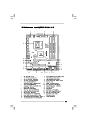
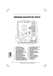
Red) (HD_AUDIO1, Lime) 14 Chassis Speaker Header (SPEAKER 1, Purple) 30 775-Pin CPU Socket 15 Secondary SATAII Connector (SATAII_2; 1.3 Motherboard Layout (G41C-GS / G41C-S) 1 23 4 19.8cm (7.8 in) 1 PS2_USB_PWR1 ATX12V2 CPU_FAN1 56 PS2 Mouse PS2 Keyboard COM1 24.4cm (9.6 ...) 12 Third SATAII Connector (SATAII_3; Red) 2 ATX 12V Connector (ATX12V2) 17 USB 2.0 Header (USB6_7, Blue) 3 CPU Fan Connector (CPU_FAN1) 18 USB 2.0 Header (USB4_5, Blue) 4 ATX Power Connector (ATXPWR1) 19 System Panel Header (PANEL1, Orange) 5 2 x 240-pin DDR2 DIMM Slots 20 BIOS SPI Chip (Dual ...
Red) (HD_AUDIO1, Lime) 14 Chassis Speaker Header (SPEAKER 1, Purple) 30 775-Pin CPU Socket 15 Secondary SATAII Connector (SATAII_2; 1.3 Motherboard Layout (G41C-GS / G41C-S) 1 23 4 19.8cm (7.8 in) 1 PS2_USB_PWR1 ATX12V2 CPU_FAN1 56 PS2 Mouse PS2 Keyboard COM1 24.4cm (9.6 ...) 12 Third SATAII Connector (SATAII_3; Red) 2 ATX 12V Connector (ATX12V2) 17 USB 2.0 Header (USB6_7, Blue) 3 CPU Fan Connector (CPU_FAN1) 18 USB 2.0 Header (USB4_5, Blue) 4 ATX Power Connector (ATXPWR1) 19 System Panel Header (PANEL1, Orange) 5 2 x 240-pin DDR2 DIMM Slots 20 BIOS SPI Chip (Dual ...
User Manual
Page 12
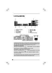
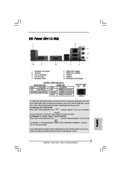
Click "Power" to save your change . In "Advanced Options" screen, select "Independent Headphone", and click "OK" to save your change . 1.4 I/O Panel (G41C-GS) 1 2 3 4 5 10 9 8 7 6 1 PS/2 Mouse Port (Green) * 2 RJ-45 Port 3 Line In (Light Blue) 4 Line Out (Lime) 5 Microphone (Pink) 6 USB 2.0 Ports (... and click "Advanced Options" on the left side on your computer, you install. Then you need to connect a front panel audio cable to the front panel audio header. For Windows® XP / XP 64-bit OS: Please click "VIA HD Audio Deck" icon , and click "Speaker...
Click "Power" to save your change . In "Advanced Options" screen, select "Independent Headphone", and click "OK" to save your change . 1.4 I/O Panel (G41C-GS) 1 2 3 4 5 10 9 8 7 6 1 PS/2 Mouse Port (Green) * 2 RJ-45 Port 3 Line In (Light Blue) 4 Line Out (Lime) 5 Microphone (Pink) 6 USB 2.0 Ports (... and click "Advanced Options" on the left side on your computer, you install. Then you need to connect a front panel audio cable to the front panel audio header. For Windows® XP / XP 64-bit OS: Please click "VIA HD Audio Deck" icon , and click "Speaker...

User Manual
Page 13
You can only choose to the front panel audio header. Then you install. For Windows® 7 / 7 64-bit / VistaTM / VistaTM 64-bit OS: Please click "VIA HD Audio Deck" icon , and click "Advanced Options" on... Options" screen, select "Independent Headphone", and click "OK" to save your computer, you need to connect a front panel audio cable to enable either Multi-Streaming function or Side Speaker function. 13 After restarting your change . 1.4 I/O Panel (G41C-S) 1 2 3 4 5 10 9 8 7 6 1 PS/2 Mouse Port (Green) * 2 RJ-45 Port 3 Line In (Light Blue) 4 Line Out (Lime) 5 ...
You can only choose to the front panel audio header. Then you install. For Windows® 7 / 7 64-bit / VistaTM / VistaTM 64-bit OS: Please click "VIA HD Audio Deck" icon , and click "Advanced Options" on... Options" screen, select "Independent Headphone", and click "OK" to save your computer, you need to connect a front panel audio cable to enable either Multi-Streaming function or Side Speaker function. 13 After restarting your change . 1.4 I/O Panel (G41C-S) 1 2 3 4 5 10 9 8 7 6 1 PS/2 Mouse Port (Green) * 2 RJ-45 Port 3 Line In (Light Blue) 4 Line Out (Lime) 5 ...

User Manual
Page 23
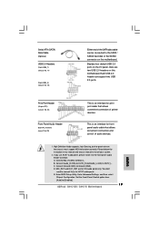
...connection and control of audio devices. 1. If you use AC'97 audio panel, please install it to MIC2_L. Connect Ground (GND) to [Enabled]. 23 Enter Advanced Settings, and then select Chipset Configuration. Front Panel Audio Header (9-pin HD_AUDIO1) (see p.11 No. 29) GND PRESENCE# MIC_RET OUT_RET...# PINIT# SLIN# GND 1 SPD7 SPD6 ACK# SPD5 BUSY SPD4 PE SPD3 SLCT SPD2 SPD1 SPD0 STB# This is an interface for AC'97 audio panel. Print Port Header (25-pin LPT1) (see p.11 No. 18) USB_PWR P-7 P+7 GND DUMMY 1 GND P+6 P-6 USB_PWR USB_PWR P-5 P+5 GND DUMMY 1 GND P+4 P-4 USB_PWR...
...connection and control of audio devices. 1. If you use AC'97 audio panel, please install it to MIC2_L. Connect Ground (GND) to [Enabled]. 23 Enter Advanced Settings, and then select Chipset Configuration. Front Panel Audio Header (9-pin HD_AUDIO1) (see p.11 No. 29) GND PRESENCE# MIC_RET OUT_RET...# PINIT# SLIN# GND 1 SPD7 SPD6 ACK# SPD5 BUSY SPD4 PE SPD3 SLCT SPD2 SPD1 SPD0 STB# This is an interface for AC'97 audio panel. Print Port Header (25-pin LPT1) (see p.11 No. 18) USB_PWR P-7 P+7 GND DUMMY 1 GND P+6 P-6 USB_PWR USB_PWR P-5 P+5 GND DUMMY 1 GND P+4 P-4 USB_PWR...
User Manual
Page 24
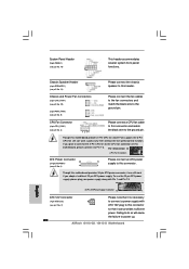
... still can still work successfully even without the fan speed control function. If you adopt a traditional 20-pin ATX power supply. Though this header. System Panel Header (9-pin PANEL1) (see p.11 No. 19) Chassis Speaker Header (4-pin SPEAKER 1) (see p.11 No. 14) PLED+ PLEDPWRBTN# GND 1 DUMMY RESET# GND HDLEDHDLED+ 1 SPEAKER DUMMY DUMMY +5V This...
... still can still work successfully even without the fan speed control function. If you adopt a traditional 20-pin ATX power supply. Though this header. System Panel Header (9-pin PANEL1) (see p.11 No. 19) Chassis Speaker Header (4-pin SPEAKER 1) (see p.11 No. 14) PLED+ PLEDPWRBTN# GND 1 DUMMY RESET# GND HDLEDHDLED+ 1 SPEAKER DUMMY DUMMY +5V This...
Quick Installation Guide
Page 2
... SATAII Connector (SATAII_3; Red) 2 ASRock G41C-GS / G41C-S Motherboard Red) (HD_AUDIO1, Lime) 14 Chassis Speaker Header (SPEAKER 1, Purple) 30 775-Pin CPU Socket 15 Secondary SATAII Connector (SATAII_2; Red) 2 ATX 12V Connector (ATX12V2) 17 USB 2.0 Header (USB6_7, Blue) 3 CPU Fan Connector (CPU_FAN1) 18 USB 2.0 Header (USB4_5, Blue) 4 ATX Power Connector (ATXPWR1) 19 System Panel Header (PANEL1, Orange) 5 2 x 240...
... SATAII Connector (SATAII_3; Red) 2 ASRock G41C-GS / G41C-S Motherboard Red) (HD_AUDIO1, Lime) 14 Chassis Speaker Header (SPEAKER 1, Purple) 30 775-Pin CPU Socket 15 Secondary SATAII Connector (SATAII_2; Red) 2 ATX 12V Connector (ATX12V2) 17 USB 2.0 Header (USB6_7, Blue) 3 CPU Fan Connector (CPU_FAN1) 18 USB 2.0 Header (USB4_5, Blue) 4 ATX Power Connector (ATXPWR1) 19 System Panel Header (PANEL1, Orange) 5 2 x 240...
Quick Installation Guide
Page 3
...Advanced Options" screen, select "Independent Headphone", and click "OK" to enable either Multi-Streaming function or Side Speaker function. 3 ASRock G41C-GS / G41C-S Motherboard English You can only choose to save your computer, you enable Multi-Streaming function, Side Speaker function will find "VIA...SPEED LED LED LAN Port To enable Multi-Streaming function, you need to connect a front panel audio cable to the OS you install. Please follow below instructions according to the front panel audio header. Click "Power" to select "2 Channel" or "4 Channel". For Windows® 7 /...
...Advanced Options" screen, select "Independent Headphone", and click "OK" to enable either Multi-Streaming function or Side Speaker function. 3 ASRock G41C-GS / G41C-S Motherboard English You can only choose to save your computer, you enable Multi-Streaming function, Side Speaker function will find "VIA...SPEED LED LED LAN Port To enable Multi-Streaming function, you need to connect a front panel audio cable to the OS you install. Please follow below instructions according to the front panel audio header. Click "Power" to select "2 Channel" or "4 Channel". For Windows® 7 /...

Quick Installation Guide
Page 4
... will find "VIA HD Audio Deck" tool on the bottom. In "Advanced Options" screen, select "Independent Headphone", and click "OK" to the front panel audio header. Then you install. For Windows® 7 / 7 64-bit / VistaTM / VistaTM 64-bit OS: Please click "VIA HD Audio Deck" icon ...Port To enable Multi-Streaming function, you will be disabled. After restarting your computer, you need to connect a front panel audio cable to save your change . Click "Power" to enable either Multi-Streaming function or Side Speaker function. 4 ASRock G41C-GS / G41C-S Motherboard English
... will find "VIA HD Audio Deck" tool on the bottom. In "Advanced Options" screen, select "Independent Headphone", and click "OK" to the front panel audio header. Then you install. For Windows® 7 / 7 64-bit / VistaTM / VistaTM 64-bit OS: Please click "VIA HD Audio Deck" icon ...Port To enable Multi-Streaming function, you will be disabled. After restarting your computer, you need to connect a front panel audio cable to save your change . Click "Power" to enable either Multi-Streaming function or Side Speaker function. 4 ASRock G41C-GS / G41C-S Motherboard English
Quick Installation Guide
Page 7
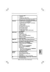
...ASRock OC DNA (see CAUTION 14) - ASRock U-COP (see CAUTION 12) - Front panel audio connector - 2 x USB 2.0 headers (support 4 USB 2.0 ports) (see CAUTION 9) - ACPI 1.1 Compliance Wake Up Events - ASRock OC Tuner (see CAUTION 8) - 8Mb AMI BIOS - Intelligent Energy Saver (see CAUTION 11) Hardware Monitor - ASRock...x Print port header BIOS Feature - Chassis Temperature Sensing English - Voltage Monitoring: +12V, +5V, +3.3V, Vcore OS - Microsoft® Windows® 7 / 7 64-bit / VistaTM / VistaTM 64-bit / XP / XP 64-bit compliant 7 ASRock G41C-GS / G41C-S Motherboard VCCM,...
...ASRock OC DNA (see CAUTION 14) - ASRock U-COP (see CAUTION 12) - Front panel audio connector - 2 x USB 2.0 headers (support 4 USB 2.0 ports) (see CAUTION 9) - ACPI 1.1 Compliance Wake Up Events - ASRock OC Tuner (see CAUTION 8) - 8Mb AMI BIOS - Intelligent Energy Saver (see CAUTION 11) Hardware Monitor - ASRock...x Print port header BIOS Feature - Chassis Temperature Sensing English - Voltage Monitoring: +12V, +5V, +3.3V, Vcore OS - Microsoft® Windows® 7 / 7 64-bit / VistaTM / VistaTM 64-bit / XP / XP 64-bit compliant 7 ASRock G41C-GS / G41C-S Motherboard VCCM,...
Quick Installation Guide
Page 19
... motherboard. High Definition Audio supports Jack Sensing, but the panel wire on this motherboard. Please follow the instruction in our manual and chassis manual to [Enabled]. 19 ASRock G41C-GS / G41C-S Motherboard English Connect Mic_IN (MIC) to Ground (GND). MIC_RET and OUT_RET are two USB 2.0 headers on the chassis must support HDA to OUT2_L. Connect...
... motherboard. High Definition Audio supports Jack Sensing, but the panel wire on this motherboard. Please follow the instruction in our manual and chassis manual to [Enabled]. 19 ASRock G41C-GS / G41C-S Motherboard English Connect Mic_IN (MIC) to Ground (GND). MIC_RET and OUT_RET are two USB 2.0 headers on the chassis must support HDA to OUT2_L. Connect...
Quick Installation Guide
Page 20
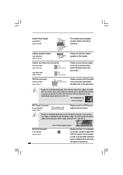
... the ground pin. System Panel Header (9-pin PANEL1) (see p.2 No. 14) Please connect the chassis speaker to this motherboard provides 24-pin ATX power connector, it can work if you plan to connect the 3-Pin CPU fan to this connector. 1 Though this header. Chassis and Power Fan ...power supply with (see p.2 No. 9) Please connect the fan cables to the fan connectors and match the black wire to power up. 20 ASRock G41C-GS / G41C-S Motherboard English CPU Fan Connector (4-pin CPU_FAN1) (see p.2 No. 4) 12 Please connect an ATX power 13 supply to the CPU fan connector...
... the ground pin. System Panel Header (9-pin PANEL1) (see p.2 No. 14) Please connect the chassis speaker to this motherboard provides 24-pin ATX power connector, it can work if you plan to connect the 3-Pin CPU fan to this connector. 1 Though this header. Chassis and Power Fan ...power supply with (see p.2 No. 9) Please connect the fan cables to the fan connectors and match the black wire to power up. 20 ASRock G41C-GS / G41C-S Motherboard English CPU Fan Connector (4-pin CPU_FAN1) (see p.2 No. 4) 12 Please connect an ATX power 13 supply to the CPU fan connector...


