User Manual
Page 3
...Contents 5 1.2 Specifications 6 1.3 Motherboard Layout (G41C-GS / G41C-S 11 1.4 I/O Panel (G41C-GS 12 1.5 I/O Panel (G41C-S 13 2 Installation 14 2.1 Screw Holes 14 2.2 Pre-installation Precautions 14 2.3 CPU Installation 15 2.4 Installation of Heatsink and CPU fan 17 2.5 Installation of Memory Modules (DIMM...Menu Bar 27 3.1.2 Navigation Keys 28 3.2 Main Screen 28 3.3 OC Tweaker Screen 30 3.4 Advanced Screen 34 3.4.1 CPU Configuration 35 3.4.2 Chipset Configuration 37 3.4.3 ACPI Configuration 42 3.4.4 Storage Configuration 43 3.4.5 PCIPnP Configuration 45 3.4.6 Floppy ...
...Contents 5 1.2 Specifications 6 1.3 Motherboard Layout (G41C-GS / G41C-S 11 1.4 I/O Panel (G41C-GS 12 1.5 I/O Panel (G41C-S 13 2 Installation 14 2.1 Screw Holes 14 2.2 Pre-installation Precautions 14 2.3 CPU Installation 15 2.4 Installation of Heatsink and CPU fan 17 2.5 Installation of Memory Modules (DIMM...Menu Bar 27 3.1.2 Navigation Keys 28 3.2 Main Screen 28 3.3 OC Tweaker Screen 30 3.4 Advanced Screen 34 3.4.1 CPU Configuration 35 3.4.2 Chipset Configuration 37 3.4.3 ACPI Configuration 42 3.4.4 Storage Configuration 43 3.4.5 PCIPnP Configuration 45 3.4.6 Floppy ...
User Manual
Page 5
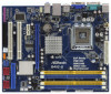
... and endurance. You may find the latest VGA cards and CPU support lists on ASRock website without notice. www.asrock.com/support/index.asp 1.1 Package Contents ASRock G41C-GS / G41C-S Motherboard (Micro ATX Form Factor: 9.6-in x 7.8-in, 24.4 cm x 19.8 cm) ASRock G41C-GS / G41C-S Quick Installation Guide ASRock G41C-GS / G41C-S Support CD Two Serial ATA (SATA) Data Cables (Optional) One...
... and endurance. You may find the latest VGA cards and CPU support lists on ASRock website without notice. www.asrock.com/support/index.asp 1.1 Package Contents ASRock G41C-GS / G41C-S Motherboard (Micro ATX Form Factor: 9.6-in x 7.8-in, 24.4 cm x 19.8 cm) ASRock G41C-GS / G41C-S Quick Installation Guide ASRock G41C-GS / G41C-S Support CD Two Serial ATA (SATA) Data Cables (Optional) One...

User Manual
Page 6
... x PCI Express x16 slot - 1 x PCI Express x1 slot - 2 x PCI slots - Max. capacity of system memory: 8GB (see CAUTION 4) - G41C-S: Realtek PCIE x1 LAN 8103EL / 8102EL, speed 10/100 Mb/s - Supports Untied Overclocking Technology (see CAUTION 3) - 2 x DDR3 DIMM slots - Dual Channel...: Intel® G41 - Supports DDR2 800/667/533 non-ECC, un-buffered memory (see CAUTION 5) - 2 x DDR2 DIMM slots - Max. 1.2 Specifications Platform CPU Chipset Memory Expansion Slot Graphics Audio LAN Rear Panel I /O Panel - 1 x PS/2 Mouse Port - 1 x PS/2 Keyboard Port 6 Micro ATX Form Factor: ...
... x PCI Express x16 slot - 1 x PCI Express x1 slot - 2 x PCI slots - Max. capacity of system memory: 8GB (see CAUTION 4) - G41C-S: Realtek PCIE x1 LAN 8103EL / 8102EL, speed 10/100 Mb/s - Supports Untied Overclocking Technology (see CAUTION 3) - 2 x DDR3 DIMM slots - Dual Channel...: Intel® G41 - Supports DDR2 800/667/533 non-ECC, un-buffered memory (see CAUTION 5) - 2 x DDR2 DIMM slots - Max. 1.2 Specifications Platform CPU Chipset Memory Expansion Slot Graphics Audio LAN Rear Panel I /O Panel - 1 x PS/2 Mouse Port - 1 x PS/2 Keyboard Port 6 Micro ATX Form Factor: ...

User Manual
Page 7
... Suite and Creative Sound Blaster X-Fi MB) (OEM and Trial Version) - ASRock Instant Flash (see CAUTION 14) - ASRock U-COP (see CAUTION 11) - Voltage Monitoring: +12V, +5V, +3.3V, Vcore - Hybrid Booster: - Chassis Temperature Sensing - CPU/Chassis/Power Fan Tachometer - SMBIOS 2.3.1 Support - Supports Smart BIOS - CPU/Chassis/Power FAN connector - 24 pin ATX power connector - 4 pin...
... Suite and Creative Sound Blaster X-Fi MB) (OEM and Trial Version) - ASRock Instant Flash (see CAUTION 14) - ASRock U-COP (see CAUTION 11) - Voltage Monitoring: +12V, +5V, +3.3V, Vcore - Hybrid Booster: - Chassis Temperature Sensing - CPU/Chassis/Power Fan Tachometer - SMBIOS 2.3.1 Support - Supports Smart BIOS - CPU/Chassis/Power FAN connector - 24 pin ATX power connector - 4 pin...

User Manual
Page 8
... Disk Setup Guide" on this motherboard, it will run at your system stability, or even cause damage to page 22 for the CPU FSB frequency and its corresponding memory support frequency. It should be less than 4GB for the reservation for possible damage caused by the chipset... supply is required) (see CAUTION 15) * For detailed product information, please visit our website: http://www.asrock.com WARNING Please realize that there is a certain risk involved with 64-bit CPU, there is subject to SATAII connector directly. 8 Overclocking may be done at DDR3 533 if you adopt a...
... Disk Setup Guide" on this motherboard, it will run at your system stability, or even cause damage to page 22 for the CPU FSB frequency and its corresponding memory support frequency. It should be less than 4GB for the reservation for possible damage caused by the chipset... supply is required) (see CAUTION 15) * For detailed product information, please visit our website: http://www.asrock.com WARNING Please realize that there is a certain risk involved with 64-bit CPU, there is subject to SATAII connector directly. 8 Overclocking may be done at DDR3 533 if you adopt a...
User Manual
Page 9
... in a few clicks without preparing an additional floppy diskette or other than the recommended CPU bus frequencies may cause the instability of overclocking settings. In other words, it back again. ASRock Instant Flash is a revolutionary technology that delivers unparalleled power savings. This convenient BIOS update...profile can press key during the POST or press key to BIOS setup menu to perform over-clocking. While CPU overheat is not recommended to access ASRock Instant Flash. The software name itself - It helps you can update your BIOS only in Flash ROM. ...
... in a few clicks without preparing an additional floppy diskette or other than the recommended CPU bus frequencies may cause the instability of overclocking settings. In other words, it back again. ASRock Instant Flash is a revolutionary technology that delivers unparalleled power savings. This convenient BIOS update...profile can press key during the POST or press key to BIOS setup menu to perform over-clocking. While CPU overheat is not recommended to access ASRock Instant Flash. The software name itself - It helps you can update your BIOS only in Flash ROM. ...
User Manual
Page 11
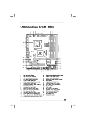
... Red) (HD_AUDIO1, Lime) 14 Chassis Speaker Header (SPEAKER 1, Purple) 30 775-Pin CPU Socket 15 Secondary SATAII Connector (SATAII_2; Red) 2 ATX 12V Connector (ATX12V2) 17 USB 2.0 Header (USB6_7, Blue) 3 CPU Fan Connector (CPU_FAN1) 18 USB 2.0 Header (USB4_5, Blue) 4 ATX Power Connector (ATXPWR1... Jumper (EUP_AUDIO1) 11 IDE1 Connector (IDE1, Blue) 28 EUP LAN Jumper (EUP_LAN1) 12 Third SATAII Connector (SATAII_3; 1.3 Motherboard Layout (G41C-GS / G41C-S) 1 23 4 19.8cm (7.8 in) 1 PS2_USB_PWR1 ATX12V2 CPU_FAN1 56 PS2 Mouse PS2 Keyboard COM1 24.4cm (9.6 in) DDR3_B1 (64 ...
... Red) (HD_AUDIO1, Lime) 14 Chassis Speaker Header (SPEAKER 1, Purple) 30 775-Pin CPU Socket 15 Secondary SATAII Connector (SATAII_2; Red) 2 ATX 12V Connector (ATX12V2) 17 USB 2.0 Header (USB6_7, Blue) 3 CPU Fan Connector (CPU_FAN1) 18 USB 2.0 Header (USB4_5, Blue) 4 ATX Power Connector (ATXPWR1... Jumper (EUP_AUDIO1) 11 IDE1 Connector (IDE1, Blue) 28 EUP LAN Jumper (EUP_LAN1) 12 Third SATAII Connector (SATAII_3; 1.3 Motherboard Layout (G41C-GS / G41C-S) 1 23 4 19.8cm (7.8 in) 1 PS2_USB_PWR1 ATX12V2 CPU_FAN1 56 PS2 Mouse PS2 Keyboard COM1 24.4cm (9.6 in) DDR3_B1 (64 ...

User Manual
Page 15
... Sink) up. Step 1-2. black line black line Step 2-2. Orient the CPU with black lines. Otherwise, the CPU will be seriously damaged. Rotate the load lever to insert the CPU into the socket, please check if the CPU surface is unclean or if there is found. Step 2. Do not force... to fully open position at approximately 135 degrees. Open the socket: CPU Marked Corner Step 1-1. Hold the CPU by depressing down and out on the socket. 2.3 CPU Installation For the installation of Intel 775-LAND CPU, please follow the steps below. 775-Pin Socket Overview Before you insert ...
... Sink) up. Step 1-2. black line black line Step 2-2. Orient the CPU with black lines. Otherwise, the CPU will be seriously damaged. Rotate the load lever to insert the CPU into the socket, please check if the CPU surface is unclean or if there is found. Step 2. Do not force... to fully open position at approximately 135 degrees. Open the socket: CPU Marked Corner Step 1-1. Hold the CPU by depressing down and out on the socket. 2.3 CPU Installation For the installation of Intel 775-LAND CPU, please follow the steps below. 775-Pin Socket Overview Before you insert ...
User Manual
Page 16
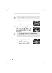
Step 2-4. Step 4-2. Verify that the CPU is recommended to use the cap tab to handle and avoid kicking off the PnP cap. 2. Remove PnP Cap (Pick and Place Cap): Use your ... onto the IHS. For proper inserting, please ensure to match the two orientation key notches of the CPU with the two alignment keys of PnP cap to assist in removal. 1. Step 4-3. Carefully place the CPU into the socket by using a purely vertical motion. Step 4. It is within the socket and properly mated...
Step 2-4. Step 4-2. Verify that the CPU is recommended to use the cap tab to handle and avoid kicking off the PnP cap. 2. Remove PnP Cap (Pick and Place Cap): Use your ... onto the IHS. For proper inserting, please ensure to match the two orientation key notches of the CPU with the two alignment keys of PnP cap to assist in removal. 1. Step 4-3. Carefully place the CPU into the socket by using a purely vertical motion. Step 4. It is within the socket and properly mated...
User Manual
Page 17
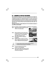
... socket. Step 6. Connect fan header with each other components. 17 Ensure that supports Intel 775-LAND CPU. Step 3. Ensure fan cables are securely fastened and in good contact with the CPU fan connector on the motherboard (CPU_FAN1, see page 11, No. 3). Repeat with 775-Pin socket ...press down on fastener caps with fan operation or contact other . 2.4 Installation of CPU Fan and Heatsink This motherboard is an example to illustrate the installation of the heatsink for 775-LAND CPU. Apply thermal interface material onto center of heatsink and cooling fan compliant with the ...
... socket. Step 6. Connect fan header with each other components. 17 Ensure that supports Intel 775-LAND CPU. Step 3. Ensure fan cables are securely fastened and in good contact with the CPU fan connector on the motherboard (CPU_FAN1, see page 11, No. 3). Repeat with 775-Pin socket ...press down on fastener caps with fan operation or contact other . 2.4 Installation of CPU Fan and Heatsink This motherboard is an example to illustrate the installation of the heatsink for 775-LAND CPU. Apply thermal interface material onto center of heatsink and cooling fan compliant with the ...

User Manual
Page 22
...No. 16) (SATAII_2: see p.11, No. 15) SATAII_1 (SATAII_3: see p.11, No. 12) (SATAII_4: see p.11 No. 25) FSB1 Default If you adopt FSB1333-CPU and DDR3 1333 memory module on this motherboard, you need to the instruction of the connector. Please short pin2, pin3 for the details. Placing jumper... headers and connectors. Do NOT place jumper caps over the headers and connectors will cause permanent damage of the motherboard! Otherwise, the CPU and memory module may not work properly on this motherboard. The current SATAII interface allows up to below jumper setting.
...No. 16) (SATAII_2: see p.11, No. 15) SATAII_1 (SATAII_3: see p.11, No. 12) (SATAII_4: see p.11 No. 25) FSB1 Default If you adopt FSB1333-CPU and DDR3 1333 memory module on this motherboard, you need to the instruction of the connector. Please short pin2, pin3 for the details. Placing jumper... headers and connectors. Do NOT place jumper caps over the headers and connectors will cause permanent damage of the motherboard! Otherwise, the CPU and memory module may not work properly on this motherboard. The current SATAII interface allows up to below jumper setting.
User Manual
Page 24
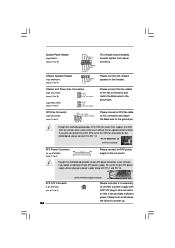
... If you adopt a traditional 20-pin ATX power supply. Failing to do so will cause the failure to this motherboard provides 4-Pin CPU fan (Quiet Fan) support, the 3-Pin CPU fan still can provides sufficient power. Chassis and Power Fan Connectors (3-pin CHA_FAN1) (see p.11 No. 10) GND +12V CHA_FAN_SPEED (3-...with ATX 12V plug to this motherboard provides 24-pin ATX power connector, it can work if you plan to connect the 3-Pin CPU fan to the CPU fan connector on this connector and match the black wire to the ground pin. Pin 1-3 Connected 3-Pin Fan Installation ATX Power Connector...
... If you adopt a traditional 20-pin ATX power supply. Failing to do so will cause the failure to this motherboard provides 4-Pin CPU fan (Quiet Fan) support, the 3-Pin CPU fan still can provides sufficient power. Chassis and Power Fan Connectors (3-pin CHA_FAN1) (see p.11 No. 10) GND +12V CHA_FAN_SPEED (3-...with ATX 12V plug to this motherboard provides 24-pin ATX power connector, it can work if you plan to connect the 3-Pin CPU fan to the CPU fan connector on this connector and match the black wire to the ground pin. Pin 1-3 Connected 3-Pin Fan Installation ATX Power Connector...
User Manual
Page 26
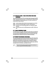
... set the selection from up to bottom side to install the SATA / SATAII hard disks. Then, the drivers compatible to fixed PCI / PCIE buses. Therefore, CPU FSB is untied during overclocking, FSB enjoys better margin due to your optical drive first. STEP 3: Connect one end of the SATA data cable to...
... set the selection from up to bottom side to install the SATA / SATAII hard disks. Then, the drivers compatible to fixed PCI / PCIE buses. Therefore, CPU FSB is untied during overclocking, FSB enjoys better margin due to your optical drive first. STEP 3: Connect one end of the SATA data cable to...
User Manual
Page 28
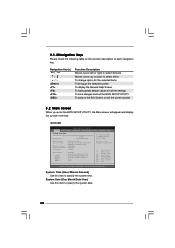
...To display the General Help Screen To load optimal default values for the function description of each navigation key. BIOS Version : G41C-GS P1.00 Processor Type : Intel (R) Core (TM) 2 Duo CPU E8200 @ 2.66GHz (64bit) Processor Speed : 2666MHz Microcode Update : 10676/60C Cache Size : 6144KB Total Memory DDRII1 DDRII2...] Use this item to select items To change option for the selected items To bring up or down to specify the system time. G41C-GS BIOS SETUP UTILITY Main OC Tweaker Advanced H/W Monitor Boot Security Exit System Overview System Time System Date [14:00:09] [Tue...
...To display the General Help Screen To load optimal default values for the function description of each navigation key. BIOS Version : G41C-GS P1.00 Processor Type : Intel (R) Core (TM) 2 Duo CPU E8200 @ 2.66GHz (64bit) Processor Speed : 2666MHz Microcode Update : 10676/60C Cache Size : 6144KB Total Memory DDRII1 DDRII2...] Use this item to select items To change option for the selected items To bring up or down to specify the system time. G41C-GS BIOS SETUP UTILITY Main OC Tweaker Advanced H/W Monitor Boot Security Exit System Overview System Time System Date [14:00:09] [Tue...
User Manual
Page 29
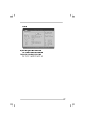
System Time [Hour:Minute:Second] Use this item to specify the system time. BIOS Version : G41C-S P1.00 Processor Type : Intel (R) Core (TM) 2 Duo CPU E8200 @ 2.66GHz (64bit) Processor Speed : 2666MHz Microcode Update : 10676/60C Cache Size : 6144KB Total Memory DDRII1 DDRII2 DDR3_1 DDR3_2 : 2048MB ...None : None Use [+] or [-] to select a field. System Date [Day Month/Date/Year] Use this item to specify the system date. 29 G41C-S BIOS SETUP UTILITY Main OC Tweaker Advanced H/W Monitor Boot Security Exit System Overview System Time System Date [14:00:09] [Tue 12/01/2009] ...
System Time [Hour:Minute:Second] Use this item to specify the system time. BIOS Version : G41C-S P1.00 Processor Type : Intel (R) Core (TM) 2 Duo CPU E8200 @ 2.66GHz (64bit) Processor Speed : 2666MHz Microcode Update : 10676/60C Cache Size : 6144KB Total Memory DDRII1 DDRII2 DDR3_1 DDR3_2 : 2048MB ...None : None Use [+] or [-] to select a field. System Date [Day Month/Date/Year] Use this item to specify the system date. 29 G41C-S BIOS SETUP UTILITY Main OC Tweaker Advanced H/W Monitor Boot Security Exit System Overview System Time System Date [14:00:09] [Tue 12/01/2009] ...
User Manual
Page 30
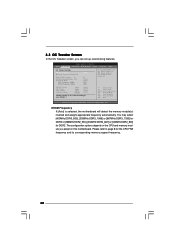
...] is selected, the motherboard will detect the memory module(s) inserted and assigns appropriate frequency automatically. The configuration options depend on the CPU and memory module you like to Sub Screen F1 General Help F9 Load Defaults F10 Save and Exit ESC Exit v02.54 (C) ...], [533MHz DDR3_1066] or [667MHz DDR3_1333] for DDR3 or [266MHz DDR2_533], [333MHz DDR2_667] or [400MHz DDR2_800] for the CPU FSB frequency and its corresponding memory support frequency. 30 Overclock Mode CPU Frequency (MHz) PCIE Frequency (MHz) [Auto] [8] [Auto] [Auto] [333] [100] If you adopt DDR3 1333...
...] is selected, the motherboard will detect the memory module(s) inserted and assigns appropriate frequency automatically. The configuration options depend on the CPU and memory module you like to Sub Screen F1 General Help F9 Load Defaults F10 Save and Exit ESC Exit v02.54 (C) ...], [533MHz DDR3_1066] or [667MHz DDR3_1333] for DDR3 or [266MHz DDR2_533], [333MHz DDR2_667] or [400MHz DDR2_800] for the CPU FSB frequency and its corresponding memory support frequency. 30 Overclock Mode CPU Frequency (MHz) PCIE Frequency (MHz) [Auto] [8] [Auto] [Auto] [333] [100] If you adopt DDR3 1333...

User Manual
Page 32
... SpeedStep(tm) tech." is [Auto]. Please note that enabling this to enable power savings. Overclock Mode Use this function may reduce CPU voltage and lead to select NB Voltage. Configuration options for DDR2: [Auto], [1.66V] to enable this option to [1.30V]. Processor ... technology. Configuration options: [Auto], [1.05V] to adjust PCIE frequency. Ratio CMOS Setting If the ratio status is unlocked, you will be hidden if the current CPU does not support Intel (R) SpeedStep(tm) tech.. in advance. Configuration options: [Auto], [0.67 x Vtt], [0.65 x Vtt], [0.63 x Vtt] and...
... SpeedStep(tm) tech." is [Auto]. Please note that enabling this to enable power savings. Overclock Mode Use this function may reduce CPU voltage and lead to select NB Voltage. Configuration options for DDR2: [Auto], [1.66V] to enable this option to [1.30V]. Processor ... technology. Configuration options: [Auto], [1.05V] to adjust PCIE frequency. Ratio CMOS Setting If the ratio status is unlocked, you will be hidden if the current CPU does not support Intel (R) SpeedStep(tm) tech.. in advance. Configuration options: [Auto], [0.67 x Vtt], [0.65 x Vtt], [0.63 x Vtt] and...

User Manual
Page 34
... Floppy Configuration SuperIO Configuration USB Configuration BIOS Update Utility ASRock Instant Flash Select Screen Select Item Enter Go to malfunction. 34 3.4 Advanced Screen In this section, you may set the configurations for CPU WARNING : Setting wrong values in this section may cause... SETUP UTILITY Main OC Tweaker Advanced H/W Monitor Boot Security Exit Advanced Settings Options for the following items: CPU Configuration, Chipset Configuration, ACPI Configuration, Storage Configuration, PCIPnP Configuration, Floppy Configuration, SuperIO Configuration, and USB Configuration.
... Floppy Configuration SuperIO Configuration USB Configuration BIOS Update Utility ASRock Instant Flash Select Screen Select Item Enter Go to malfunction. 34 3.4 Advanced Screen In this section, you may set the configurations for CPU WARNING : Setting wrong values in this section may cause... SETUP UTILITY Main OC Tweaker Advanced H/W Monitor Boot Security Exit Advanced Settings Options for the following items: CPU Configuration, Chipset Configuration, ACPI Configuration, Storage Configuration, PCIPnP Configuration, Floppy Configuration, SuperIO Configuration, and USB Configuration.

User Manual
Page 35
... MWAIT and requires no hardware support from the chipset. Spread Spectrum This item should always be hidden if the installed CPU does not support Intel (R) Virtualization Technology. 35 Overclock Mode Use this option to adjust PCIE frequency. This option will...the option " Intel (R) SpeedStep(tm) tech." Enhance Halt State All processors support the Halt State (C1). PCIE Frequency (MHz) Use this to adjust CPU frequency. Configuration options: [Auto], [Manual] and [Optimized]. When this option to select Overclock Mode. On-Demand Clock Modulation [Auto] [333] [100]...
... MWAIT and requires no hardware support from the chipset. Spread Spectrum This item should always be hidden if the installed CPU does not support Intel (R) Virtualization Technology. 35 Overclock Mode Use this option to adjust PCIE frequency. This option will...the option " Intel (R) SpeedStep(tm) tech." Enhance Halt State All processors support the Halt State (C1). PCIE Frequency (MHz) Use this to adjust CPU frequency. Configuration options: [Auto], [Manual] and [Optimized]. When this option to select Overclock Mode. On-Demand Clock Modulation [Auto] [333] [100]...
User Manual
Page 36
... default value is Intel's new power saving technology. It indicates the clock on to [Enabled]. This option will be hidden if the current CPU does not support No-Excute Memory Protection. For example, if you install Windows® VistaTM and want to enable this function, please set ... On], [62.5% On], [75.0% On] and [87.5% On]. Intel (R) SpeedStep(tm) tech. If you set this function may select [Enabled] to enable P4 CPU internal thermal control mechanism to execute code. Set to the IA-32 Intel Architecture. The default value is an enhancement to [Enabled] if using Microsoft...
... default value is Intel's new power saving technology. It indicates the clock on to [Enabled]. This option will be hidden if the current CPU does not support No-Excute Memory Protection. For example, if you install Windows® VistaTM and want to enable this function, please set ... On], [62.5% On], [75.0% On] and [87.5% On]. Intel (R) SpeedStep(tm) tech. If you set this function may select [Enabled] to enable P4 CPU internal thermal control mechanism to execute code. Set to the IA-32 Intel Architecture. The default value is an enhancement to [Enabled] if using Microsoft...


