
User Manual
Page 3
... Guide ...23 2.10 Serial ATA (SATA) / Serial ATAII (SATAII) Hard Disks Installation ...24 2.11 Driver Installation Guide ...24 2.12 Untied Overclocking Technology ...24 3 BIOS S ETUP UTILITY ...25 SETUP 3.1 Introduction ...3.1.1 BIOS Menu Bar ...3.1.2 Navigation Keys ...3.2 Main Screen ...3.3 Smart Screen ...3.4 Advanced Screen ...3.4.1 CPU Configuration ...3.4.2 Chipset Configuration ...3.4.3 ACPI Configuration ...3.4.4 IDE Configuration ...3.4.5 PCIPnP Configuration ...3.4.6 Super IO...
... Guide ...23 2.10 Serial ATA (SATA) / Serial ATAII (SATAII) Hard Disks Installation ...24 2.11 Driver Installation Guide ...24 2.12 Untied Overclocking Technology ...24 3 BIOS S ETUP UTILITY ...25 SETUP 3.1 Introduction ...3.1.1 BIOS Menu Bar ...3.1.2 Navigation Keys ...3.2 Main Screen ...3.3 Smart Screen ...3.4 Advanced Screen ...3.4.1 CPU Configuration ...3.4.2 Chipset Configuration ...3.4.3 ACPI Configuration ...3.4.4 IDE Configuration ...3.4.5 PCIPnP Configuration ...3.4.6 Super IO...

User Manual
Page 5
... to BIOS setup and information of this manual will be subject to this motherboard, please visit our website for purchasing ASRock G31M-VS motherboard, a reliable motherboard produced under ASRock's consistently stringent quality control. www.asrock.com/support/index.asp 1.1 P ack age Contents Pack ackage ASRock G31M-VS Motherboard (Micro ATX Form Factor: 8.8-in x 6.7-in, 22.4 cm x 17.0 cm) ASRock G31M-VS Quick...
... to BIOS setup and information of this manual will be subject to this motherboard, please visit our website for purchasing ASRock G31M-VS motherboard, a reliable motherboard produced under ASRock's consistently stringent quality control. www.asrock.com/support/index.asp 1.1 P ack age Contents Pack ackage ASRock G31M-VS Motherboard (Micro ATX Form Factor: 8.8-in x 6.7-in, 22.4 cm x 17.0 cm) ASRock G31M-VS Quick...

User Manual
Page 7
...Support for RAID and "Hot Plug" functions) (see CAUTION 11) - CD in header - ACPI 1.1 Compliance Wake Up Events - Supports Smart BIOS - ASRock U-COP (see CAUTION 6) - 1 x ATA100 IDE connector (supports 2 x IDE devices) - 1 x Print port header - FCC, CE *... For detailed product information, please visit our website: http://www.asrock.com 7 Front panel audio connector - 2 x USB 2.0 headers (support 4 USB 2.0 ports) (see CAUTION 8) - ASRock OC Tuner (see CAUTION 7) - 4Mb AMI BIOS - Drivers, Utilities, AntiVirus Software (Trial Version) - Supports jumperfree ...
...Support for RAID and "Hot Plug" functions) (see CAUTION 11) - CD in header - ACPI 1.1 Compliance Wake Up Events - Supports Smart BIOS - ASRock U-COP (see CAUTION 6) - 1 x ATA100 IDE connector (supports 2 x IDE devices) - 1 x Print port header - FCC, CE *... For detailed product information, please visit our website: http://www.asrock.com 7 Front panel audio connector - 2 x USB 2.0 headers (support 4 USB 2.0 ports) (see CAUTION 8) - ASRock OC Tuner (see CAUTION 7) - 4Mb AMI BIOS - Drivers, Utilities, AntiVirus Software (Trial Version) - Supports jumperfree ...

User Manual
Page 8
... maximum shared memory size is defined by overclocking. Please check Intel ® website for the operation procedures of ASRock OC Tuner. ASRock website: http://www.asrock.com 9. In other words, it is a revolutionary technology that there is a certain risk involved with 64-... Windows® VistaTM 64bit with overclocking, including adjusting the setting in the BIOS, applying Untied Overclocking Technology, or using the thirdparty overclocking tools. directly. It is a user-friendly ASRock overclocking tool which allows you implement Dual Channel Memory Technology, make sure to...
... maximum shared memory size is defined by overclocking. Please check Intel ® website for the operation procedures of ASRock OC Tuner. ASRock website: http://www.asrock.com 9. In other words, it is a revolutionary technology that there is a certain risk involved with 64-... Windows® VistaTM 64bit with overclocking, including adjusting the setting in the BIOS, applying Untied Overclocking Technology, or using the thirdparty overclocking tools. directly. It is a user-friendly ASRock overclocking tool which allows you implement Dual Channel Memory Technology, make sure to...

User Manual
Page 10
...SATAII_2; Red) USB 2.0 Header (USB4_5, Blue) Chassis Fan Connector (CHA_FAN1) Clear CMOS Jumper (CLRCMOS1) USB 2.0 Header (USB6_7, Blue) PCI Slot (PCI1) BIOS SPI Chip PCI Express x16 Slot (PCIE1) Internal Audio Connector: CD1 (Black) Front Panel Audio Header (HD_AUDIO1, Lime) Print Port Header (LPT1, Purple) 10 1.3...Mic In Top: Line In LAN PHY LPT1 Intel G31 Chipset 21 20 19 HD_AUDIO1 G31M-VS USB 2.0 T: USB2 B: USB3 22.4cm (8.8 in) 1 COM1 VGA1 1 6 PCIE1 CD1 AUDIO CODEC 18 17 16 15 4Mb BIOS CMOS Battery RoHS PCI1 Intel ICH7 IDE1 PANEL 1 PLED PWRBTN 7 USB6_7 CHA_FAN1 1 ...
...SATAII_2; Red) USB 2.0 Header (USB4_5, Blue) Chassis Fan Connector (CHA_FAN1) Clear CMOS Jumper (CLRCMOS1) USB 2.0 Header (USB6_7, Blue) PCI Slot (PCI1) BIOS SPI Chip PCI Express x16 Slot (PCIE1) Internal Audio Connector: CD1 (Black) Front Panel Audio Header (HD_AUDIO1, Lime) Print Port Header (LPT1, Purple) 10 1.3...Mic In Top: Line In LAN PHY LPT1 Intel G31 Chipset 21 20 19 HD_AUDIO1 G31M-VS USB 2.0 T: USB2 B: USB3 22.4cm (8.8 in) 1 COM1 VGA1 1 6 PCIE1 CD1 AUDIO CODEC 18 17 16 15 4Mb BIOS CMOS Battery RoHS PCI1 Intel ICH7 IDE1 PANEL 1 PLED PWRBTN 7 USB6_7 CHA_FAN1 1 ...

User Manual
Page 17
... for the card before you install the add-on PCI Express VGA card to PCIE1 (PCIE x16 slot) and adjust the "Internal Graphics Mode Select" BIOS option to PCIE1 (PCIE x16 slot), the onboard VGA will be disabled. If you start the installation. 2.6 Expansion Slots (PCI and PCI Express Slots) There...
... for the card before you install the add-on PCI Express VGA card to PCIE1 (PCIE x16 slot) and adjust the "Internal Graphics Mode Select" BIOS option to PCIE1 (PCIE x16 slot), the onboard VGA will be disabled. If you start the installation. 2.6 Expansion Slots (PCI and PCI Express Slots) There...

User Manual
Page 21
... HD Audio Manager. To activate the front mic. Please connect a CPU fan cable to this connector and match the black wire to this header. Enter BIOS Setup Utility. Enter Windows system. Click the icon on the lower right hand taskbar to [Enabled]. For Windows® VistaTM / VistaTM 64-bit OS: Go...
... HD Audio Manager. To activate the front mic. Please connect a CPU fan cable to this connector and match the black wire to this header. Enter BIOS Setup Utility. Enter Windows system. Click the icon on the lower right hand taskbar to [Enabled]. For Windows® VistaTM / VistaTM 64-bit OS: Go...

User Manual
Page 24
... Technology. 24 Please refer to the warning on the support CD driver page. STEP 1: Install the SATA / SATAII hard disks into the drive bays of BIOS setup to set the selection from up to bottom side to install those required drivers. You may install SATA / SATAII hard disks on this motherboard...
... Technology. 24 Please refer to the warning on the support CD driver page. STEP 1: Install the SATA / SATAII hard disks into the drive bays of BIOS setup to set the selection from up to bottom side to install those required drivers. You may install SATA / SATAII hard disks on this motherboard...

User Manual
Page 25
You may also restart by pressing the reset button on your system. Chapter 3: BIOS SETUP UTILITY 3.1 Introduction This section explains how to use the BIOS SETUP UTILITY to configure your screen. 3 . 1 . 1 BIOS Menu Bar The top of the screen has a menu bar with its test routines. Please press during ...being updated, the following selections: Main To set up the system time/date information Smart To load the BIOS according to your requirements Advanced To set up the advanced BIOS features H/W Monitor To display current hardware status Boot To set up the default system device to locate and...
You may also restart by pressing the reset button on your system. Chapter 3: BIOS SETUP UTILITY 3.1 Introduction This section explains how to use the BIOS SETUP UTILITY to configure your screen. 3 . 1 . 1 BIOS Menu Bar The top of the screen has a menu bar with its test routines. Please press during ...being updated, the following selections: Main To set up the system time/date information Smart To load the BIOS according to your requirements Advanced To set up the advanced BIOS features H/W Monitor To display current hardware status Boot To set up the default system device to locate and...

User Manual
Page 26
... specify the system date. 26 System Date [Day Month/Date/Year] Use this item to specify the system time. Use [+] or [-] to configure system Time. : G31M-VS P1.00 : Intel (R) CPU 2.80GHz (64bit) : 2800MHz Processor Speed Microcode Update : F62/F : 4096KB Cache Size Total Memory DDRII 1 DDRII 2 : 1024MB with 8MB shared memory...54 (C) Copyright 1985-2005, American Megatrends, Inc. 3 . 1 . 2 Navigation Keys Please check the following table for all the settings To save changes and exit the BIOS SETUP UTILITY To jump to the Exit Screen or exit the current screen 3.2 Main Screen When you enter the...
... specify the system date. 26 System Date [Day Month/Date/Year] Use this item to specify the system time. Use [+] or [-] to configure system Time. : G31M-VS P1.00 : Intel (R) CPU 2.80GHz (64bit) : 2800MHz Processor Speed Microcode Update : F62/F : 4096KB Cache Size Total Memory DDRII 1 DDRII 2 : 1024MB with 8MB shared memory...54 (C) Copyright 1985-2005, American Megatrends, Inc. 3 . 1 . 2 Navigation Keys Please check the following table for all the settings To save changes and exit the BIOS SETUP UTILITY To jump to the Exit Screen or exit the current screen 3.2 Main Screen When you enter the...

User Manual
Page 27
... Setup Default (IDE/SATA) Load Power Saving Setup Default Exit system setup after loading, please resume optimal default settings. F5 key can load the BIOS setup according to your requirements. Save Changes and Exit When you can be used for this operation. Enter F1 F9 F10 ESC Select Screen Select... Item Go to save the changes and exit the BIOS SETUP UTILITY. 3.3 Smart Screen In the Smart screen, you select this option, it will pop-out the following message, "Save configuration changes and exit...
... Setup Default (IDE/SATA) Load Power Saving Setup Default Exit system setup after loading, please resume optimal default settings. F5 key can load the BIOS setup according to your requirements. Save Changes and Exit When you can be used for this operation. Enter F1 F9 F10 ESC Select Screen Select... Item Go to save the changes and exit the BIOS SETUP UTILITY. 3.3 Smart Screen In the Smart screen, you select this option, it will pop-out the following message, "Save configuration changes and exit...

User Manual
Page 28
... set the configurations for CPU Advanced Settings WARNING : Setting wrong values in this section may cause system to malfunction. BIOS SETUP UTILITY H/W Monitor Boot Main Smart Advanced Security Exit Options for the following items: CPU Configuration, Chipset Configuration, ACPI Configuration,...Inc. Overclock Mode Use this option to adjust CPU frequency. CPU Frequency (MHz) Use this to malfunction. 3.4.1 CPU Configuration BIOS SETUP UTILITY Advanced CPU Configuration Overclock Mode CPU Frequency (MHz) PCIE Frequency (MHz) Boot Failure Guard Spread Spectrum Ratio Status ...
... set the configurations for CPU Advanced Settings WARNING : Setting wrong values in this section may cause system to malfunction. BIOS SETUP UTILITY H/W Monitor Boot Main Smart Advanced Security Exit Options for the following items: CPU Configuration, Chipset Configuration, ACPI Configuration,...Inc. Overclock Mode Use this option to adjust CPU frequency. CPU Frequency (MHz) Use this to malfunction. 3.4.1 CPU Configuration BIOS SETUP UTILITY Advanced CPU Configuration Overclock Mode CPU Frequency (MHz) PCIE Frequency (MHz) Boot Failure Guard Spread Spectrum Ratio Status ...

User Manual
Page 30
... between multiple frequency and voltage points to enable or disable memory remap feature. Please set this item to [Disable] if above issue occurs. 3.4.2 Chipset Configuration BIOS SETUP UTILITY Advanced Chipset Settings Memory Remap Feature DRAM Frequency Flexibility Option DRAM tCL DRAM tRCD DRAM tRP DRAM tRAS Primary Graphics Adapter Internal Graphics...
... between multiple frequency and voltage points to enable or disable memory remap feature. Please set this item to [Disable] if above issue occurs. 3.4.2 Chipset Configuration BIOS SETUP UTILITY Advanced Chipset Settings Memory Remap Feature DRAM Frequency Flexibility Option DRAM tCL DRAM tRCD DRAM tRP DRAM tRAS Primary Graphics Adapter Internal Graphics...

User Manual
Page 32
...]. DRAM Voltage Use this feature is [Auto]. The default value of this to select +1.5V Voltage. The default value of this to [Enabled]. Besides the BIOS option, you want to enable this function, please set this item to adjust DRAM RCOMP Setting feature. DRAM RCOMP Setting Use this feature is [Auto...
...]. DRAM Voltage Use this feature is [Auto]. The default value of this to select +1.5V Voltage. The default value of this to [Enabled]. Besides the BIOS option, you want to enable this function, please set this item to adjust DRAM RCOMP Setting feature. DRAM RCOMP Setting Use this feature is [Auto...

User Manual
Page 33
... to use this item to enable or disable RTC (Real Time Clock) to power on the system from the power-soft-off mode. 3.4.3 ACPI Configuration BIOS SETUP UTILITY Advanced ACPI Configuration Suspend To RAM Restore on AC/Power Loss This allows you to set this option to [Enabled] if you to...
... to use this item to enable or disable RTC (Real Time Clock) to power on the system from the power-soft-off mode. 3.4.3 ACPI Configuration BIOS SETUP UTILITY Advanced ACPI Configuration Suspend To RAM Restore on AC/Power Loss This allows you to set this option to [Enabled] if you to...

User Manual
Page 34
... Configuration You may set to select between [SATA 1, SATA 2], [SATA 1, IDE 1], and [IDE 1, SATA 2]. Set [Enhanced] when Native OS (Win2000 / XP) is used . 3.4.4 IDE Configuration BIOS SETUP UTILITY Advanced IDE Configuration ATA/IDE Configuration SATAII_1 SATAII_2 IDE1 Master IDE1 Slave [Enhanced] [Hard Disk] [Not Detected] [Not Detected] [Not Detected] Set [Compatible...
... Configuration You may set to select between [SATA 1, SATA 2], [SATA 1, IDE 1], and [IDE 1, SATA 2]. Set [Enhanced] when Native OS (Win2000 / XP) is used . 3.4.4 IDE Configuration BIOS SETUP UTILITY Advanced IDE Configuration ATA/IDE Configuration SATAII_1 SATAII_2 IDE1 Master IDE1 Slave [Enhanced] [Hard Disk] [Not Detected] [Not Detected] [Not Detected] Set [Compatible...

User Manual
Page 35
...allows the improved transfer-speed and data-integrity for a hard disk > 512 MB under DOS and Windows; After selecting the hard disk information into BIOS, use of the IDE device that you specify. for IDE ARMD (ATAPI Removable Media Device), such as FDISK, to disable the LBA/Large mode....This is used for IDE CD/DVD drives. [ARMD]: This is enabled, it will enhance hard disk performance by optimizing the hard disk timing. BIOS SETUP UTILITY Advanced Primary IDE Master Device Vendor Size LBA Mode Block Mode PIO Mode Async DMA Ultra DMA S.M.A.R.T. Block (Multi-Sector Transfer) The ...
...allows the improved transfer-speed and data-integrity for a hard disk > 512 MB under DOS and Windows; After selecting the hard disk information into BIOS, use of the IDE device that you specify. for IDE ARMD (ATAPI Removable Media Device), such as FDISK, to disable the LBA/Large mode....This is used for IDE CD/DVD drives. [ARMD]: This is enabled, it will enhance hard disk performance by optimizing the hard disk timing. BIOS SETUP UTILITY Advanced Primary IDE Master Device Vendor Size LBA Mode Block Mode PIO Mode Async DMA Ultra DMA S.M.A.R.T. Block (Multi-Sector Transfer) The ...

User Manual
Page 36
... require other settings. It is 32. PCI Latency Timer The default value is recommended to maximize the IDE hard disk data transfer rate. 3.4.5 PCIPnP Configuration BIOS SETUP UTILITY Advanced Advanced PCI / PnP Settings PCI Latency Timer PCI IDE BusMaster [32] [Enabled] Value in units of PCI clocks for PCI device latency...
... require other settings. It is 32. PCI Latency Timer The default value is recommended to maximize the IDE hard disk data transfer rate. 3.4.5 PCIPnP Configuration BIOS SETUP UTILITY Advanced Advanced PCI / PnP Settings PCI Latency Timer PCI IDE BusMaster [32] [Enabled] Value in units of PCI clocks for PCI device latency...

User Manual
Page 37
...]. Parallel Port Mode Use this option is [ECP+EPP]. Configuration options: [DMA0], [DMA1], and [DMA3]. Configuration options: [1.9] and [1.7]. 3.4.6 Super IO Configuration BIOS SETUP UTILITY Advanced Configure Super IO Chipset Serial Port Address Parallel Port Address Parallel Port Mode EPP Version ECP Mode DMA Channel Parallel Port IRQ... [3F8 / IRQ4] [378] [ECP + EPP] [1.9] [DMA3] [IRQ7] Allow BIOS to [ECP+EPP], it will show the EPP version in the following item, "EPP Version". If this item to set the ECP mode DMA ...
...]. Parallel Port Mode Use this option is [ECP+EPP]. Configuration options: [DMA0], [DMA1], and [DMA3]. Configuration options: [1.9] and [1.7]. 3.4.6 Super IO Configuration BIOS SETUP UTILITY Advanced Configure Super IO Chipset Serial Port Address Parallel Port Address Parallel Port Mode EPP Version ECP Mode DMA Channel Parallel Port IRQ... [3F8 / IRQ4] [378] [ECP + EPP] [1.9] [DMA3] [IRQ7] Allow BIOS to [ECP+EPP], it will show the EPP version in the following item, "EPP Version". If this item to set the ECP mode DMA ...
User Manual
Page 38
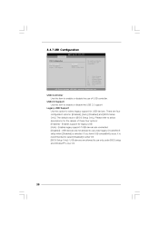
...and Windows® / Linux OS. 38 USB Controller Use this option to enable or disable the use only under legacy OS and BIOS setup when [Disabled] is [BIOS Setup Only]. Legacy USB Support Use this item to select legacy support for legacy USB. [Auto] - Enables support for USB devices.... USB devices are allowed to enter OS. [BIOS Setup Only] - Please refer to enable or disable the USB 2.0 support. If you have USB compatibility issue, it is recommended to select [Disabled]...
...and Windows® / Linux OS. 38 USB Controller Use this option to enable or disable the use only under legacy OS and BIOS setup when [Disabled] is [BIOS Setup Only]. Legacy USB Support Use this item to select legacy support for legacy USB. [Auto] - Enables support for USB devices.... USB devices are allowed to enter OS. [BIOS Setup Only] - Please refer to enable or disable the USB 2.0 support. If you have USB compatibility issue, it is recommended to select [Disabled]...


