User Manual
Page 3
... 2 Installation 12 2.1 Screw Holes 12 2.2 Pre-installation Precautions 12 2.3 CPU Installation 13 2.4 Installation of Heatsink and CPU fan 15 2.5 Installation of Memory Modules (DIMM 16 2.6 Expansion Slots (PCI, HDMR, and PCI Express Slots) ....... 18 2.7 DVI Graphics-SI Card Installation Guide 18 2.8 Jumpers Setup 20 2.9 Onboard Headers and Connectors 21 2.10 SATAII Hard...
... 2 Installation 12 2.1 Screw Holes 12 2.2 Pre-installation Precautions 12 2.3 CPU Installation 13 2.4 Installation of Heatsink and CPU fan 15 2.5 Installation of Memory Modules (DIMM 16 2.6 Expansion Slots (PCI, HDMR, and PCI Express Slots) ....... 18 2.7 DVI Graphics-SI Card Installation Guide 18 2.8 Jumpers Setup 20 2.9 Onboard Headers and Connectors 21 2.10 SATAII Hard...
User Manual
Page 7
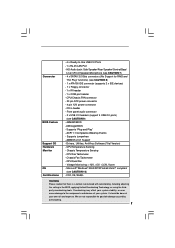
...applying Untied Overclocking Technology, or using the thirdparty overclocking tools. Drivers, Utilities, AntiVirus Software (Trial Version) - CPU/Chassis FAN connector - 20 pin ATX power connector - 4 pin 12V power connector - Supports jumperfree - Microsoft® Windows®...header - 1 x COM port header - Front panel audio connector - 2 x USB 2.0 headers (support 4 USB 2.0 ports) (see CAUTION 10) - Chassis Fan Tachometer - Connector BIOS Feature Support CD Hardware Monitor OS Certifications - 4 x Ready-to the components and devices of your own risk and expense. ACPI 1.1 Compliance ...
...applying Untied Overclocking Technology, or using the thirdparty overclocking tools. Drivers, Utilities, AntiVirus Software (Trial Version) - CPU/Chassis FAN connector - 20 pin ATX power connector - 4 pin 12V power connector - Supports jumperfree - Microsoft® Windows®...header - 1 x COM port header - Front panel audio connector - 2 x USB 2.0 headers (support 4 USB 2.0 ports) (see CAUTION 10) - Chassis Fan Tachometer - Connector BIOS Feature Support CD Hardware Monitor OS Certifications - 4 x Ready-to the components and devices of your own risk and expense. ACPI 1.1 Compliance ...
User Manual
Page 8
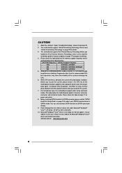
... power cord, then plug it to spray thermal grease between the CPU and the heatsink when you resume the system, please check if the CPU fan on page 17 for Microsoft® Windows® VistaTM driver and related information. Although this motherboard offers stepless control, it is not recommended to SATAII... Guide" on page 24 to adjust your SATAII hard disk drive to read "Untied Overclocking Technology" on page 11 for details. 3. We will automatically shutdown. ASRock website http://www...
... power cord, then plug it to spray thermal grease between the CPU and the heatsink when you resume the system, please check if the CPU fan on page 17 for Microsoft® Windows® VistaTM driver and related information. Although this motherboard offers stepless control, it is not recommended to SATAII... Guide" on page 24 to adjust your SATAII hard disk drive to read "Untied Overclocking Technology" on page 11 for details. 3. We will automatically shutdown. ASRock website http://www...

User Manual
Page 10
Red) 30 Infrared Module Header (IR1) 10 Red) 3 CPU Fan Connector (CPU_FAN1) 17 Chassis Fan Connector (CHA_FAN1) 4 775-Pin CPU Socket 18 USB 2.0 Header (USB6_7, Blue) 5 North Bridge Controller 19 USB 2.0 Header (USB4_5, Blue) 6 Clear CMOS Jumper (CLRCMOS1) ... Intel ICH7 SATAII 1 USB4_5 IDE1 1 USB6_7 SATAII_3 SATAII_1 USB2.0 CHA_FAN1 SATAII_4 SATAII_2 SPEAKER1 1 PANEL 1 PLED PWRBTN 1 HDLED RESET Dual Core CPU Dual Channel ConRoe945G-DVI 22 21 20 19 18 17 161514 13 DDRII667 24.4cm (9.6 in) 9 10 11 12 1 PS2_USB_PWR1 Jumper 15 Third SATAII Connector (SATAII_3;
Red) 30 Infrared Module Header (IR1) 10 Red) 3 CPU Fan Connector (CPU_FAN1) 17 Chassis Fan Connector (CHA_FAN1) 4 775-Pin CPU Socket 18 USB 2.0 Header (USB6_7, Blue) 5 North Bridge Controller 19 USB 2.0 Header (USB4_5, Blue) 6 Clear CMOS Jumper (CLRCMOS1) ... Intel ICH7 SATAII 1 USB4_5 IDE1 1 USB6_7 SATAII_3 SATAII_1 USB2.0 CHA_FAN1 SATAII_4 SATAII_2 SPEAKER1 1 PANEL 1 PLED PWRBTN 1 HDLED RESET Dual Core CPU Dual Channel ConRoe945G-DVI 22 21 20 19 18 17 161514 13 DDRII667 24.4cm (9.6 in) 9 10 11 12 1 PS2_USB_PWR1 Jumper 15 Third SATAII Connector (SATAII_3;

User Manual
Page 15
... ensure cable does not interfere with Intel 775-LAND CPU to install and lock. Please adopt the type of heatsink and cooling fan compliant with fan operation or contact other . Step 1. For proper installation, please kindly refer to the instruction manuals of IHS on the motherboard.... Apply thermal interface material onto center of your CPU fan and heatsink. Align fasteners with remaining fasteners. 2.4 Installation of CPU Fan and Heatsink This motherboard is an example to illustrate the installation of the heatsink for 775-LAND CPU...
... ensure cable does not interfere with Intel 775-LAND CPU to install and lock. Please adopt the type of heatsink and cooling fan compliant with fan operation or contact other . Step 1. For proper installation, please kindly refer to the instruction manuals of IHS on the motherboard.... Apply thermal interface material onto center of your CPU fan and heatsink. Align fasteners with remaining fasteners. 2.4 Installation of CPU Fan and Heatsink This motherboard is an example to illustrate the installation of the heatsink for 775-LAND CPU...

User Manual
Page 23
... power supply to this connector. Please connect the chassis speaker to this header. Chassis Fan Connector (3-pin CHA_FAN1) (see p.10 No. 3) +12V CPU_FAN_SPEED GND FAN_SPEED_CONTROL Please connect a CPU fan cable to this connector and match the black wire to this connector and match the black...Manager. Click the icon on the lower right hand taskbar to the ground pin. CPU Fan Connector (4-pin CPU_FAN1) (see p.10 No. 17) GND +12V CHA_FAN_SPEED Please connect a chassis fan cable to this connector so that it can provides sufficient power. This COM1 header supports a...
... power supply to this connector. Please connect the chassis speaker to this header. Chassis Fan Connector (3-pin CHA_FAN1) (see p.10 No. 3) +12V CPU_FAN_SPEED GND FAN_SPEED_CONTROL Please connect a CPU fan cable to this connector and match the black wire to this connector and match the black...Manager. Click the icon on the lower right hand taskbar to the ground pin. CPU Fan Connector (4-pin CPU_FAN1) (see p.10 No. 17) GND +12V CHA_FAN_SPEED Please connect a chassis fan cable to this connector so that it can provides sufficient power. This COM1 header supports a...

User Manual
Page 38
... Save and Exit Exit v02.54 (C) Copyright 1985-2005, American Megatrends, Inc. Tolerance ( C) The default value of CPU fan. The default value is [Fast]. CPU Quiet Fan This item allows you choose. Configuration options: [Fast], [Middle] and [Slow]. 38 If you set this option as [...Disabled], the CPU fan will find the items "Target CPU Temperature ( C)", "Tolerance ( C)", and "Minimun Fan Speed" appear to allow you to set this option as [Enabled], you will operate in full speed. Target...
... Save and Exit Exit v02.54 (C) Copyright 1985-2005, American Megatrends, Inc. Tolerance ( C) The default value of CPU fan. The default value is [Fast]. CPU Quiet Fan This item allows you choose. Configuration options: [Fast], [Middle] and [Slow]. 38 If you set this option as [...Disabled], the CPU fan will find the items "Target CPU Temperature ( C)", "Tolerance ( C)", and "Minimun Fan Speed" appear to allow you to set this option as [Enabled], you will operate in full speed. Target...
Quick Installation Guide
Page 2
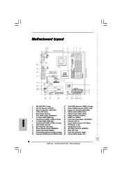
Orange) 29 Serial Port Connector (COM1) 14 Secondary SATAII Connector (SATAII_2; Red) 3 CPU Fan Connector (CPU_FAN1) 17 Chassis Fan Connector (CHA_FAN1) 4 775-Pin CPU Socket 18 USB 2.0 Header (USB6_7, Blue) 5 North Bridge Controller 19 USB 2.0 ...Chip 13 Fourth SATAII Connector (SATAII_4; Motherboard Layout English 1 PS2_USB_PWR1 Jumper 15 Third SATAII Connector (SATAII_3; Red) 30 Infrared Module Header (IR1) 2 ASRock ConRoe945G-DVI Motherboard Yellow) 22 Front Panel Audio Header (HD_AUDIO1) 8 2 x 240-pin DDRII DIMM Slots 23 PCI Slots (PCI1- 2) (Dual Channel B: ...
Orange) 29 Serial Port Connector (COM1) 14 Secondary SATAII Connector (SATAII_2; Red) 3 CPU Fan Connector (CPU_FAN1) 17 Chassis Fan Connector (CHA_FAN1) 4 775-Pin CPU Socket 18 USB 2.0 Header (USB6_7, Blue) 5 North Bridge Controller 19 USB 2.0 ...Chip 13 Fourth SATAII Connector (SATAII_4; Motherboard Layout English 1 PS2_USB_PWR1 Jumper 15 Third SATAII Connector (SATAII_3; Red) 30 Infrared Module Header (IR1) 2 ASRock ConRoe945G-DVI Motherboard Yellow) 22 Front Panel Audio Header (HD_AUDIO1) 8 2 x 240-pin DDRII DIMM Slots 23 PCI Slots (PCI1- 2) (Dual Channel B: ...

Quick Installation Guide
Page 6
... Untied Overclocking Technology, or using the thirdparty overclocking tools. Supports "Plug and Play" - CPU Fan Tachometer - CPU Quiet Fan - CPU Temperature Sensing - Chassis Fan Tachometer - It should be done at your system. Connector BIOS Feature Support CD Hardware Monitor OS...RAID and "Hot Plug" functions) (see CAUTION 6) - 4 x SATAII 3.0 Gb/s connectors (No Support for possible damage caused by overclocking. 6 ASRock ConRoe945G-DVI Motherboard Front panel audio connector - 2 x USB 2.0 headers (support 4 USB 2.0 ports) (see CAUTION 9) - Microsoft® Windows® 2000...
... Untied Overclocking Technology, or using the thirdparty overclocking tools. Supports "Plug and Play" - CPU Fan Tachometer - CPU Quiet Fan - CPU Temperature Sensing - Chassis Fan Tachometer - It should be done at your system. Connector BIOS Feature Support CD Hardware Monitor OS...RAID and "Hot Plug" functions) (see CAUTION 6) - 4 x SATAII 3.0 Gb/s connectors (No Support for possible damage caused by overclocking. 6 ASRock ConRoe945G-DVI Motherboard Front panel audio connector - 2 x USB 2.0 headers (support 4 USB 2.0 ports) (see CAUTION 9) - Microsoft® Windows® 2000...

Quick Installation Guide
Page 7
Before you install the PC system. 6. Before you resume the system, please check if the CPU fan on the motherboard functions properly and unplug the power cord, then plug it to SATAII connector, please read the ...modes. CAUTION! 1. About the setting of "Hyper Threading Technology", please check page 29 of the system or damage the CPU. 5. ASRock website http://www.asrock.com 7 ASRock ConRoe945G-DVI Motherboard English This motherboard supports Dual Channel Memory Technology. Frequencies other than the recommended CPU bus frequencies may cause the instability of "User...
Before you install the PC system. 6. Before you resume the system, please check if the CPU fan on the motherboard functions properly and unplug the power cord, then plug it to SATAII connector, please read the ...modes. CAUTION! 1. About the setting of "Hyper Threading Technology", please check page 29 of the system or damage the CPU. 5. ASRock website http://www.asrock.com 7 ASRock ConRoe945G-DVI Motherboard English This motherboard supports Dual Channel Memory Technology. Frequencies other than the recommended CPU bus frequencies may cause the instability of "User...

Quick Installation Guide
Page 11
... refer to illustrate the installation of the heatsink for after service. Step 4-3. Apply thermal interface material onto center of your CPU fan and heatsink. Place the heatsink onto the socket. Repeat with the motherboard throughholes. It is an example to the instruction manuals .... Rotate the load plate onto the IHS. Step 4. Secure excess cable with fan operation or contact other components. 11 ASRock ConRoe945G-DVI Motherboard English Below is recommended to use the cap tab to the CPU fan connector on the motherboard (CPU_FAN1, see page 2, No. 3). If you press...
... refer to illustrate the installation of the heatsink for after service. Step 4-3. Apply thermal interface material onto center of your CPU fan and heatsink. Place the heatsink onto the socket. Repeat with the motherboard throughholes. It is an example to the instruction manuals .... Rotate the load plate onto the IHS. Step 4. Secure excess cable with fan operation or contact other components. 11 ASRock ConRoe945G-DVI Motherboard English Below is recommended to use the cap tab to the CPU fan connector on the motherboard (CPU_FAN1, see page 2, No. 3). If you press...

Quick Installation Guide
Page 19
... chassis speaker to this connector and match the black wire to this connector. English 19 ASRock ConRoe945G-DVI Motherboard Enter Windows system. Chassis Speaker Header (4-pin SPEAKER 1) (see p.2 No. 12) Chassis Fan Connector (3-pin CHA_FAN1) (see p.2 No. 17) CPU Fan Connector (4-pin CPU_FAN1) (see p.2 No. 3) ATX Power Connector (20-pin ATXPWR1) (see p.2 No. 27) ATX...
... chassis speaker to this connector and match the black wire to this connector. English 19 ASRock ConRoe945G-DVI Motherboard Enter Windows system. Chassis Speaker Header (4-pin SPEAKER 1) (see p.2 No. 12) Chassis Fan Connector (3-pin CHA_FAN1) (see p.2 No. 17) CPU Fan Connector (4-pin CPU_FAN1) (see p.2 No. 3) ATX Power Connector (20-pin ATXPWR1) (see p.2 No. 27) ATX...


