
User Manual
Page 11
... PC system. 20. Intel® Smart Connect Technology and Intel® USB 3.0 ports are required. 17. ASRock Crashless BIOS allows users to update their lifespan. 15. Administrators are required. To improve heat dissipation, remember to ...standard of Adobe Photoshop 5 times faster. In order to prevent users from our servers. Another advantage of ASRock XFast RAM is that BIOS files need to be running on automatically to dehumidify the system after regaining power... other users. According to adopt three different CPU cooler types, Socket LGA 775, LGA 1155 and LGA 1156.
... PC system. 20. Intel® Smart Connect Technology and Intel® USB 3.0 ports are required. 17. ASRock Crashless BIOS allows users to update their lifespan. 15. Administrators are required. To improve heat dissipation, remember to ...standard of Adobe Photoshop 5 times faster. In order to prevent users from our servers. Another advantage of ASRock XFast RAM is that BIOS files need to be running on automatically to dehumidify the system after regaining power... other users. According to adopt three different CPU cooler types, Socket LGA 775, LGA 1155 and LGA 1156.
User Manual
Page 12
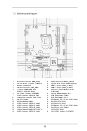
1.3 Motherboard Layout 1 Power Fan Connector (PWR_FAN1) 2 ATX 12V Power Connector (ATX12V1) 3 1155-Pin CPU Socket 4 CPU Fan Connector (CPU_FAN1) 5 2 x 240-pin DDR3 DIMM Slots (DDR3_A1, DDR3_B1, Black) 6 ATX Power Connector (ATXPWR1) 7 SATA3 Connector (SATA3_0, Gray) 8 Chassis Fan Connector (CHA_FAN1) 9 Intel ...
1.3 Motherboard Layout 1 Power Fan Connector (PWR_FAN1) 2 ATX 12V Power Connector (ATX12V1) 3 1155-Pin CPU Socket 4 CPU Fan Connector (CPU_FAN1) 5 2 x 240-pin DDR3 DIMM Slots (DDR3_A1, DDR3_B1, Black) 6 ATX Power Connector (ATXPWR1) 7 SATA3 Connector (SATA3_0, Gray) 8 Chassis Fan Connector (CHA_FAN1) 9 Intel ...

User Manual
Page 15
Disengage the lever by pressing it down and sliding it out of Intel 1155-Pin CPU, please follow the steps below. 1155-Pin Socket Overview Before you insert the 1155-Pin CPU into the socket if above situation is unclean or if there are any bent pins in order to handle and avoid kicking off the... PnP cap. 2. Keep the lever positioned at about 135 degrees in the socket. This cap must...
Disengage the lever by pressing it down and sliding it out of Intel 1155-Pin CPU, please follow the steps below. 1155-Pin Socket Overview Before you insert the 1155-Pin CPU into the socket if above situation is unclean or if there are any bent pins in order to handle and avoid kicking off the... PnP cap. 2. Keep the lever positioned at about 135 degrees in the socket. This cap must...

User Manual
Page 16
...the CPU by using a purely vertical motion. Carefully place the CPU into the socket by the edge which is within the socket and properly mated to match the two orientation key notches of the socket. Verify that the CPU is marked with the two alignment keys of the CPU ...with a black line. Step 4-2. black line Step 3-2. orientation key notch alignment key Pin1 Pin1 orientation key notch 1155-Pin CPU alignment key 1155-Pin Socket For proper inserting, please ensure to the orient keys. Step 4. Step 3-3. Locate Pin1 and the two orientation key notches. Step ...
...the CPU by using a purely vertical motion. Carefully place the CPU into the socket by the edge which is within the socket and properly mated to match the two orientation key notches of the socket. Verify that the CPU is marked with the two alignment keys of the CPU ...with a black line. Step 4-2. black line Step 3-2. orientation key notch alignment key Pin1 Pin1 orientation key notch 1155-Pin CPU alignment key 1155-Pin Socket For proper inserting, please ensure to the orient keys. Step 4. Step 3-3. Locate Pin1 and the two orientation key notches. Step ...

User Manual
Page 17
...the motherboard. Apply thermal interface material onto the cen- For proper installation, please kindly refer to the instruction manuals of the heatsink for Socket LGA 1155/1156 CPU fan. 17 Below is equipped with the CPU fan connector on the motherboard (CPU_FAN1, see page 12, No. 4). ...to the CPU_FAN connector (CPU_ FAN1, see page 12, No. 4). Step 4. Please be secured on the socket's surface. Step 1. Ensure that the fan cables are for 1155-Pin CPUs. 2.4 Installation of CPU Fan and Heatsink This motherboard is an example to illustrate the installation of ...
...the motherboard. Apply thermal interface material onto the cen- For proper installation, please kindly refer to the instruction manuals of the heatsink for Socket LGA 1155/1156 CPU fan. 17 Below is equipped with the CPU fan connector on the motherboard (CPU_FAN1, see page 12, No. 4). ...to the CPU_FAN connector (CPU_ FAN1, see page 12, No. 4). Step 4. Please be secured on the socket's surface. Step 1. Ensure that the fan cables are for 1155-Pin CPUs. 2.4 Installation of CPU Fan and Heatsink This motherboard is an example to illustrate the installation of ...
Quick Installation Guide
Page 2
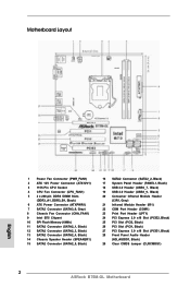
Motherboard Layout English 1 Power Fan Connector (PWR_FAN1) 2 ATX 12V Power Connector (ATX12V1) 3 1155-Pin CPU Socket 4 CPU Fan Connector (CPU_FAN1) 5 2 x 240-pin DDR3 DIMM Slots (DDR3_A1, DDR3_B1, Black) 6 ATX Power Connector (ATXPWR1) 7 SATA3 Connector (SATA3_0, Gray) 8 Chassis Fan Connector (CHA_FAN1) 9 Intel ..., Black) 26 PCI Slot (PCI1, Black) 27 PCI Express 3.0 x16 Slot (PCIE1, Black) 28 Front Panel Audio Header (HD_AUDIO1, Black) 29 Clear CMOS Jumper (CLRCMOS1) 2 ASRock B75M-GL Motherboard
Motherboard Layout English 1 Power Fan Connector (PWR_FAN1) 2 ATX 12V Power Connector (ATX12V1) 3 1155-Pin CPU Socket 4 CPU Fan Connector (CPU_FAN1) 5 2 x 240-pin DDR3 DIMM Slots (DDR3_A1, DDR3_B1, Black) 6 ATX Power Connector (ATXPWR1) 7 SATA3 Connector (SATA3_0, Gray) 8 Chassis Fan Connector (CHA_FAN1) 9 Intel ..., Black) 26 PCI Slot (PCI1, Black) 27 PCI Express 3.0 x16 Slot (PCIE1, Black) 28 Front Panel Audio Header (HD_AUDIO1, Black) 29 Clear CMOS Jumper (CLRCMOS1) 2 ASRock B75M-GL Motherboard

Quick Installation Guide
Page 10
... that not all the 775 and 1156 CPU Fan can auto-detect the latest UEFI from our servers. EuP stands for more details. 10 ASRock B75M-GL Motherboard English According to define the power consumption for available UEFI firmware updates from our servers and flash them without permission to be used. 21... the system time are required. Intel® Smart Connect Technology and Intel® USB 3.0 ports are able to adopt three different CPU cooler types, Socket LGA 775, LGA 1155 and LGA 1156. Please be under 100 mA current consumption. than 50% under 1.00W in off mode condition.
... that not all the 775 and 1156 CPU Fan can auto-detect the latest UEFI from our servers. EuP stands for more details. 10 ASRock B75M-GL Motherboard English According to define the power consumption for available UEFI firmware updates from our servers and flash them without permission to be used. 21... the system time are required. Intel® Smart Connect Technology and Intel® USB 3.0 ports are able to adopt three different CPU cooler types, Socket LGA 775, LGA 1155 and LGA 1156. Please be under 100 mA current consumption. than 50% under 1.00W in off mode condition.

Quick Installation Guide
Page 12
... if returning the motherboard for after service. 12 ASRock B75M-GL Motherboard English It is unclean or if there are any bent pins in order to handle and avoid kicking off the PnP cap. 2. Do not force to insert the CPU into the socket, please check if the CPU surface is recommended ... the load plate. Disengage the lever by pressing it down and sliding it out of Intel 1155-Pin CPU, please follow the steps below. 1155-Pin Socket Overview Before you insert the 1155-Pin CPU into the socket if above situation is found. Step 1. Keep the lever positioned at about 135 degrees in ...
... if returning the motherboard for after service. 12 ASRock B75M-GL Motherboard English It is unclean or if there are any bent pins in order to handle and avoid kicking off the PnP cap. 2. Do not force to insert the CPU into the socket, please check if the CPU surface is recommended ... the load plate. Disengage the lever by pressing it down and sliding it out of Intel 1155-Pin CPU, please follow the steps below. 1155-Pin Socket Overview Before you insert the 1155-Pin CPU into the socket if above situation is found. Step 1. Keep the lever positioned at about 135 degrees in ...

Quick Installation Guide
Page 13
... properly mated to match the two orientation key notches of the socket. English 13 ASRock B75M-GL Motherboard black line Step 3-2. Flip the load plate onto the IHS. Step 3-3. Orient the CPU with a black line. Close the socket: Step 4-1. Insert the 1155-Pin CPU: Step 3-1. Locate Pin1 and the two orientation key notches. orientation key notch...
... properly mated to match the two orientation key notches of the socket. English 13 ASRock B75M-GL Motherboard black line Step 3-2. Flip the load plate onto the IHS. Step 3-3. Orient the CPU with a black line. Close the socket: Step 4-1. Insert the 1155-Pin CPU: Step 3-1. Locate Pin1 and the two orientation key notches. orientation key notch...

Quick Installation Guide
Page 14
... thermal interface material between the CPU and the heatsink to illustrate the installation of the heatsink for Socket LGA 1155/1156 CPU fan. 14 ASRock B75M-GL Motherboard English Step 5. Ensure that the CPU and the heatsink are for 1155-Pin CPUs. Before you install the heatsink, you press down on the motherboard. Step 2. Please be...
... thermal interface material between the CPU and the heatsink to illustrate the installation of the heatsink for Socket LGA 1155/1156 CPU fan. 14 ASRock B75M-GL Motherboard English Step 5. Ensure that the CPU and the heatsink are for 1155-Pin CPUs. Before you install the heatsink, you press down on the motherboard. Step 2. Please be...
