

User Manual
Page 3
... Precautions 15 2.1 CPU Installation 16 2.2 Installation of CPU Fan and Heatsink 16 2.3 Installation of Memory Modules (DIMM 17 2.4 Expansion Slot (PCI Express Slot 18 2.5 Dual Graphics Operation Guide 19 2.6 Dual Monitor and Surround Display Features 21 2.7 ASRock Smart Remote Installation Guide 24 2.8 Jumpers Setup 25 2.9 Onboard Headers and Connectors 26 2.10 Serial...
... Precautions 15 2.1 CPU Installation 16 2.2 Installation of CPU Fan and Heatsink 16 2.3 Installation of Memory Modules (DIMM 17 2.4 Expansion Slot (PCI Express Slot 18 2.5 Dual Graphics Operation Guide 19 2.6 Dual Monitor and Surround Display Features 21 2.7 ASRock Smart Remote Installation Guide 24 2.8 Jumpers Setup 25 2.9 Onboard Headers and Connectors 26 2.10 Serial...

User Manual
Page 6
...CH HD Audio with HDMI 1.4a - Dual Channel DDR3 Memory Technology (see CAUTION 2) - Support DDR3 2400+(OC)/1866/1600/1333/ 1066/800 non-ECC, un-buffered memory (see CAUTION 1) - 2 x DDR3 DIMM slots - Max. Supports HDCP function with max. Mini-ITX Form Factor: 6.7-in x 6.7-in, 17.0 cm x... 17.0 cm - shared memory 512MB (see CAUTION 4) - AMD A75 FCH (Hudson-D3) - Supports ...
...CH HD Audio with HDMI 1.4a - Dual Channel DDR3 Memory Technology (see CAUTION 2) - Support DDR3 2400+(OC)/1866/1600/1333/ 1066/800 non-ECC, un-buffered memory (see CAUTION 1) - 2 x DDR3 DIMM slots - Max. Supports HDCP function with max. Mini-ITX Form Factor: 6.7-in x 6.7-in, 17.0 cm x... 17.0 cm - shared memory 512MB (see CAUTION 4) - AMD A75 FCH (Hudson-D3) - Supports ...

User Manual
Page 9
... that the USB ash drive or hard drive must use FAT32/16/12 le system. 9 ASRock website: http://www.asrock.com 8. This motherboard supports Dual Channel Memory Technology. ASRock website http://www.asrock.com 3. For audio output, this utility, you can update your system. Just launch this ...motherboard, please refer to the memory support list on this tool and save the new BIOS le to your USB ash...
... that the USB ash drive or hard drive must use FAT32/16/12 le system. 9 ASRock website: http://www.asrock.com 8. This motherboard supports Dual Channel Memory Technology. ASRock website http://www.asrock.com 3. For audio output, this utility, you can update your system. Just launch this ...motherboard, please refer to the memory support list on this tool and save the new BIOS le to your USB ash...

User Manual
Page 12
...IN Top: CTR BASS Center: REAR SPK Bottom: Optical SPDIF CLRCMOS1 1 1 HDMI_SPDIF1 AUDIO CODEC HD_AUDIO1 1 ATX12V1 USB_89 1 1 CIR1 1 USB_67 32Mb BIOS A75M-ITX PCIE1 AMD A75 FCH (Hudson-D3) Chipset 13 14 17.0cm (6.7-in) 21 20 19 18 17 16 15 1 CPU Fan Connector (CPU_FAN1) 14 ...Southbridge Controller 2 CPU Fan Connector (CPU_FAN2) 15 SPI Flash Memory (32Mb) 3 ATX Power Connector (ATXPWR1) 16 PCI Express 2.0 x16 Slot (PCIE1; Blue) 13 SATA3 Connector (SATA3_2, White) 12 Blue) 4 Chassis Speaker ...
...IN Top: CTR BASS Center: REAR SPK Bottom: Optical SPDIF CLRCMOS1 1 1 HDMI_SPDIF1 AUDIO CODEC HD_AUDIO1 1 ATX12V1 USB_89 1 1 CIR1 1 USB_67 32Mb BIOS A75M-ITX PCIE1 AMD A75 FCH (Hudson-D3) Chipset 13 14 17.0cm (6.7-in) 21 20 19 18 17 16 15 1 CPU Fan Connector (CPU_FAN1) 14 ...Southbridge Controller 2 CPU Fan Connector (CPU_FAN2) 15 SPI Flash Memory (32Mb) 3 ATX Power Connector (ATXPWR1) 16 PCI Express 2.0 x16 Slot (PCIE1; Blue) 13 SATA3 Connector (SATA3_2, White) 12 Blue) 4 Chassis Speaker ...

User Manual
Page 17
...that the notch on the DIMM matches the break on the slot. notch break notch break The DIMM only ts in one memory module or two non-identical memory modules, it will cause permanent damage to the motherboard and the DIMM if you always need to install two identical (the...Firmly insert the DIMM into the slot at single channel mode. 1. It is properly seated. 17 Installing a DIMM Please make sure to activate Dual Channel Memory Technology. Unlock a DIMM slot by pressing the retaining clips outward. Step 3. For dual channel configuration, you force the DIMM into the slot until the...
...that the notch on the DIMM matches the break on the slot. notch break notch break The DIMM only ts in one memory module or two non-identical memory modules, it will cause permanent damage to the motherboard and the DIMM if you always need to install two identical (the...Firmly insert the DIMM into the slot at single channel mode. 1. It is properly seated. 17 Installing a DIMM Please make sure to activate Dual Channel Memory Technology. Unlock a DIMM slot by pressing the retaining clips outward. Step 3. For dual channel configuration, you force the DIMM into the slot until the...

User Manual
Page 22
... page 18 for proper expansion card installation procedures for the second monitor. Then connect other monitor cables to the steps below. Enter "Share Memory" option to adjust the memory capability to [32MB], [64MB], [128MB], [256MB] or [512MB] to this monitor". Please make sure that you can easily enjoy ...cards on VGA card is no need to be designated as appropriate for details. 2. If you can adjust the parameters of the system memory. Install the onboard VGA driver and the add-on PCIE1 slot. Select the display icon identi ed by the number one monitor will always...
... page 18 for proper expansion card installation procedures for the second monitor. Then connect other monitor cables to the steps below. Enter "Share Memory" option to adjust the memory capability to [32MB], [64MB], [128MB], [256MB] or [512MB] to this monitor". Please make sure that you can easily enjoy ...cards on VGA card is no need to be designated as appropriate for details. 2. If you can adjust the parameters of the system memory. Install the onboard VGA driver and the add-on PCIE1 slot. Select the display icon identi ed by the number one monitor will always...

User Manual
Page 37
... Exit To exit the current screen or the UEFI SETUP UTILITY Use < > key or < > key to choose among the selections on your system. 3. The SPI Memory on the system chassis.
... Exit To exit the current screen or the UEFI SETUP UTILITY Use < > key or < > key to choose among the selections on your system. 3. The SPI Memory on the system chassis.
User Manual
Page 40
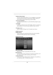
...]. 40 Con guration options: [Disabled], [Auto]. However, it is not recommended to adjust the value of CPU voltage. Bank Interleaving Interleaving allows memory accesses to keep the default value for safety and system stability, it is set to enable Channel... Memory Interleaving. The default value is selected, the motherboard will detect the memory module(s) inserted and assigns appropriate frequency automatically. Channel Interleaving It allows you to adjust GFX Engine Clock. The default ...
...]. 40 Con guration options: [Disabled], [Auto]. However, it is not recommended to adjust the value of CPU voltage. Bank Interleaving Interleaving allows memory accesses to keep the default value for safety and system stability, it is set to enable Channel... Memory Interleaving. The default value is selected, the motherboard will detect the memory module(s) inserted and assigns appropriate frequency automatically. Channel Interleaving It allows you to adjust GFX Engine Clock. The default ...

User Manual
Page 44
..., and lead to system stability or compatibility issue with some memory modules or power supplies. Please note that enabling this item to enable or disable Package C6 mode. SVM When this item to [Disable] if above ...
..., and lead to system stability or compatibility issue with some memory modules or power supplies. Please note that enabling this item to enable or disable Package C6 mode. SVM When this item to [Disable] if above ...

User Manual
Page 45
... allows you enable this option, the primary monitor will be automatically enabled when you to set the share memory feature. The default value is [PCI Express]. Use this to select the type of Primary VGA in case of this motherboard. If you to enable ...
... allows you enable this option, the primary monitor will be automatically enabled when you to set the share memory feature. The default value is [PCI Express]. Use this to select the type of Primary VGA in case of this motherboard. If you to enable ...

Quick Installation Guide
Page 2
Blue) 13 SATA3 Connector (SATA3_2, White) English 2 ASRock A75M-ITX Motherboard Blue) 4 Chassis Speaker Header (SPEAKER 1, White) 17 USB 2.0 Header (USB_89, Blue) 5 COM Port Header (COM1) 18 USB 2.0 Header (USB_67, Blue) 6 Chassis Fan Connector (CHA_FAN1) ... Center: FRONT Bottom: MIC IN Top: CTR BASS Center: REAR SPK Bottom: Optical SPDIF CLRCMOS1 1 1 HDMI_SPDIF1 AUDIO CODEC HD_AUDIO1 1 ATX12V1 USB_89 1 1 CIR1 1 USB_67 32Mb BIOS A75M-ITX PCIE1 AMD A75 FCH (Hudson-D3) Chipset 13 14 17.0cm (6.7-in) 21 20 19 18 17 16 15 1 CPU Fan Connector (CPU_FAN1) 14 Southbridge...
Blue) 13 SATA3 Connector (SATA3_2, White) English 2 ASRock A75M-ITX Motherboard Blue) 4 Chassis Speaker Header (SPEAKER 1, White) 17 USB 2.0 Header (USB_89, Blue) 5 COM Port Header (COM1) 18 USB 2.0 Header (USB_67, Blue) 6 Chassis Fan Connector (CHA_FAN1) ... Center: FRONT Bottom: MIC IN Top: CTR BASS Center: REAR SPK Bottom: Optical SPDIF CLRCMOS1 1 1 HDMI_SPDIF1 AUDIO CODEC HD_AUDIO1 1 ATX12V1 USB_89 1 1 CIR1 1 USB_67 32Mb BIOS A75M-ITX PCIE1 AMD A75 FCH (Hudson-D3) Chipset 13 14 17.0cm (6.7-in) 21 20 19 18 17 16 15 1 CPU Fan Connector (CPU_FAN1) 14 Southbridge...

Quick Installation Guide
Page 6
... automatic jutter reduction on home/online video - UMI-Link GEN2 - resolution up to 1920x1200 @ 60Hz - Supports THX TruStudioTM - 1.2 Specifications Platform CPU Chipset Memory Expansion Slot Graphics Audio LAN 6 - Mini-ITX Form Factor: 6.7-in x 6.7-in, 17.0 cm x 17.0 cm - Supports AMD's Cool 'n' QuietTM Technology - AMD A75 FCH (Hudson-D3) - Support DDR3 2400+(OC... HD Audio with HDMI (Compliant HDMI monitor is required) (see CAUTION 5) - PCIE x1 Gigabit LAN 10/100/1000 Mb/s - Realtek RTL8111E - Supports Wake-On-LAN ASRock A75M-ITX Motherboard English
... automatic jutter reduction on home/online video - UMI-Link GEN2 - resolution up to 1920x1200 @ 60Hz - Supports THX TruStudioTM - 1.2 Specifications Platform CPU Chipset Memory Expansion Slot Graphics Audio LAN 6 - Mini-ITX Form Factor: 6.7-in x 6.7-in, 17.0 cm x 17.0 cm - Supports AMD's Cool 'n' QuietTM Technology - AMD A75 FCH (Hudson-D3) - Support DDR3 2400+(OC... HD Audio with HDMI (Compliant HDMI monitor is required) (see CAUTION 5) - PCIE x1 Gigabit LAN 10/100/1000 Mb/s - Realtek RTL8111E - Supports Wake-On-LAN ASRock A75M-ITX Motherboard English

Quick Installation Guide
Page 9
...on page 14 for the compatible memory modules. Please be enabled only if the display supports 12bpc in Flash ROM. Deep Color mode will be noted that the USB flash drive or hard drive must use FAT32/16/12 file system. 9 ASRock A75M-ITX Motherboard English In IES (Intelligent ...Energy Saver), the voltage regulator can press key during the POST or press key to BIOS setup menu to the operating system limitation, the actual memory size may be less than 4GB for the reservation ...
...on page 14 for the compatible memory modules. Please be enabled only if the display supports 12bpc in Flash ROM. Deep Color mode will be noted that the USB flash drive or hard drive must use FAT32/16/12 file system. 9 ASRock A75M-ITX Motherboard English In IES (Intelligent ...Energy Saver), the voltage regulator can press key during the POST or press key to BIOS setup menu to the operating system limitation, the actual memory size may be less than 4GB for the reservation ...

Quick Installation Guide
Page 14
... is properly seated. 14 ASRock A75M-ITX Motherboard English Unlock a DIMM slot by pressing the retaining clips outward. Step 3. Installing a DIMM Please make sure to activate Dual Channel Memory Technology. notch break notch break The DIMM only fits in one memory module or two non-identical memory modules, it will cause permanent.... 2. Step 1. Align a DIMM on the slot such that the notch on the DIMM matches the break on the slot. 2.3 Installation of Memory Modules (DIMM) This motherboard provides two 240-pin DDR3 (Double Data Rate 3) DIMM slots, and supports Dual Channel...
... is properly seated. 14 ASRock A75M-ITX Motherboard English Unlock a DIMM slot by pressing the retaining clips outward. Step 3. Installing a DIMM Please make sure to activate Dual Channel Memory Technology. notch break notch break The DIMM only fits in one memory module or two non-identical memory modules, it will cause permanent.... 2. Step 1. Align a DIMM on the slot such that the notch on the DIMM matches the break on the slot. 2.3 Installation of Memory Modules (DIMM) This motherboard provides two 240-pin DDR3 (Double Data Rate 3) DIMM slots, and supports Dual Channel...

Quick Installation Guide
Page 19
...the UEFI setup, the default value of the multi-monitor according to the steps below. If you can adjust the parameters of "Share Memory", [Auto], will be designated as appropriate for the second monitor. A. C. D. Right-click the display icon and select "Attached", if...system. E. Surround Display Feature This motherboard supports surround display upgrade. Enter "Share Memory" option to adjust the memory capability to [32MB], [64MB], [128MB], [256MB] or [512MB] to four. 19 ASRock A75M-ITX Motherboard English B. Select the display icon identified by the number one monitor...
...the UEFI setup, the default value of the multi-monitor according to the steps below. If you can adjust the parameters of "Share Memory", [Auto], will be designated as appropriate for the second monitor. A. C. D. Right-click the display icon and select "Attached", if...system. E. Surround Display Feature This motherboard supports surround display upgrade. Enter "Share Memory" option to adjust the memory capability to [32MB], [64MB], [128MB], [256MB] or [512MB] to four. 19 ASRock A75M-ITX Motherboard English B. Select the display icon identified by the number one monitor...
Quick Installation Guide
Page 29
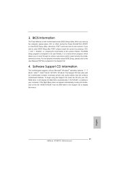
If you wish to select among the predetermined choices. 3. BIOS Information The Flash Memory on the system chassis. If the Main Menu does not appear automatically, locate and doubleclick on the file "ASSETUP.EXE" from the BIN folder ... your CDROM drive. For the detailed information about BIOS Setup, please refer to enter BIOS Setup utility; It is designed to display the menus. 29 ASRock A75M-ITX Motherboard English
If you wish to select among the predetermined choices. 3. BIOS Information The Flash Memory on the system chassis. If the Main Menu does not appear automatically, locate and doubleclick on the file "ASSETUP.EXE" from the BIN folder ... your CDROM drive. For the detailed information about BIOS Setup, please refer to enter BIOS Setup utility; It is designed to display the menus. 29 ASRock A75M-ITX Motherboard English

Quick Installation Guide
Page 125
Dual Channel Memory Technology 14 2400/1866/1600MHz CPU DDR3 2400/1866/ 1600 WEB ASRock Web サイト http://www.asrock.com Windows® 7 / VistaTM / XP 4GB 64 ビット CPU の Windows® ...7 EDID で 12bpc HBR は Windows® 7 64-bit / 7 / VistaTM 64-bit / VistaTM 2 4 6 8 3 ASRock Extreme Tuning Utility (AXTU IES IES CPU ASRock Extreme Tuning Utility (AXTU Web ASRock Web サイト :http://www.asrock.com 日本語 125 ASRock A75M-ITX Motherboard 注意 1. 2. 3. 4. 5. 6. 7.
Dual Channel Memory Technology 14 2400/1866/1600MHz CPU DDR3 2400/1866/ 1600 WEB ASRock Web サイト http://www.asrock.com Windows® 7 / VistaTM / XP 4GB 64 ビット CPU の Windows® ...7 EDID で 12bpc HBR は Windows® 7 64-bit / 7 / VistaTM 64-bit / VistaTM 2 4 6 8 3 ASRock Extreme Tuning Utility (AXTU IES IES CPU ASRock Extreme Tuning Utility (AXTU Web ASRock Web サイト :http://www.asrock.com 日本語 125 ASRock A75M-ITX Motherboard 注意 1. 2. 3. 4. 5. 6. 7.

Quick Installation Guide
Page 144
BIOS 信息 Flash Memory 存儲了 BIOS POST F2> 或 < D e l B I O S P O S T P O S T B I O S Ctrl>++ HDMI_SPDIF 接頭 (2 針 HDMI_SPDIF1) ( 見第 2 頁第 22 項 ) 1 GND SPDIFOUT HDMI_SPDIF SPDIF HDMI HDMI HDMI 顯卡的 HDMI_SPDIF 2.
BIOS 信息 Flash Memory 存儲了 BIOS POST F2> 或 < D e l B I O S P O S T P O S T B I O S Ctrl>++ HDMI_SPDIF 接頭 (2 針 HDMI_SPDIF1) ( 見第 2 頁第 22 項 ) 1 GND SPDIFOUT HDMI_SPDIF SPDIF HDMI HDMI HDMI 顯卡的 HDMI_SPDIF 2.

Quick Installation Guide
Page 156
HDMI_SPDIF 接頭 (2 針 HDMI_SPDIF1) ( 見第 2 頁第 22 項 ) 1 GND SPDIFOUT HDMI_SPDIF SPDIF H D M I HDMI HDMI HDMI_SPDIF 2. BIOS 訊息 Flash Memory BIOS POST F2> 或 + +
HDMI_SPDIF 接頭 (2 針 HDMI_SPDIF1) ( 見第 2 頁第 22 項 ) 1 GND SPDIFOUT HDMI_SPDIF SPDIF H D M I HDMI HDMI HDMI_SPDIF 2. BIOS 訊息 Flash Memory BIOS POST F2> 或 + +

RAID Installation Guide
Page 20
... PC or server, launch Windows, and log in folder _jvm under Windows environment. Its browser-based GUI provides email notification of all major events/alarms, memory cache management, drive event logging, logical drive maintenance, rebuild, and access to all programs. If you do not have one of RAIDXpert Installation Software RAIDXpert...
... PC or server, launch Windows, and log in folder _jvm under Windows environment. Its browser-based GUI provides email notification of all major events/alarms, memory cache management, drive event logging, logical drive maintenance, rebuild, and access to all programs. If you do not have one of RAIDXpert Installation Software RAIDXpert...

