RAID Installation Guide
Page 1
... ... 5 1.3.1 Installing Windows XP / XP 64-bit With RAID Funtions 5 1.3.2 Installing Windows 7 / 7 64-bit / Vista / Vista 64-bit With RAID Funtions 6 1.4 Opening Option ROM 7 1.5 Using the Main Menu 8 1.6 Viewing Drive Assignments 9 1.7 Secure Erasing a Physical Drive 10 1.8 Creating a Logical Drive 12 1.9 Deleting a Logical Drive 17 1.10 Viewing Controller Configuration 18 1.11 Responding to...
... ... 5 1.3.1 Installing Windows XP / XP 64-bit With RAID Funtions 5 1.3.2 Installing Windows 7 / 7 64-bit / Vista / Vista 64-bit With RAID Funtions 6 1.4 Opening Option ROM 7 1.5 Using the Main Menu 8 1.6 Viewing Drive Assignments 9 1.7 Secure Erasing a Physical Drive 10 1.8 Creating a Logical Drive 12 1.9 Deleting a Logical Drive 17 1.10 Viewing Controller Configuration 18 1.11 Responding to...

RAID Installation Guide
Page 8
Press 4 to create a logical drive or view information about an existing logical drive. The Main Menu (above) has five options: Press 1 to view physical drive assignments Press 2 to view the controller configuration. 1.5 Using the Main Menu When the Option ROM displays on your PC. 8 Press Esc (Escape) to exit the utility and reboot your computer screen, press Ctrl-F to delete a logical drive. Press 3 to enter the Utility and display the Main Menu.
Press 4 to create a logical drive or view information about an existing logical drive. The Main Menu (above) has five options: Press 1 to view physical drive assignments Press 2 to view the controller configuration. 1.5 Using the Main Menu When the Option ROM displays on your PC. 8 Press Esc (Escape) to exit the utility and reboot your computer screen, press Ctrl-F to delete a logical drive. Press 3 to enter the Utility and display the Main Menu.

RAID Installation Guide
Page 9
1.6 Viewing Drive Assignments From the Main Menu screen, press 1 to create a new logical drive. This screen reports physical drive assignments and provides the following information: Port: ID - Shows the AMD motherboard ...
1.6 Viewing Drive Assignments From the Main Menu screen, press 1 to create a new logical drive. This screen reports physical drive assignments and provides the following information: Port: ID - Shows the AMD motherboard ...

RAID Installation Guide
Page 10
The Secure Erase feature overwrites all data on a physical drive. To secure erase a physical drive: 1 From the Main Menu screen, press 1 to see the View Drive Assignments screen. 2 Press the arrow keys to highlight a physical drive you want . Optional. Important Once you begin, ...
The Secure Erase feature overwrites all data on a physical drive. To secure erase a physical drive: 1 From the Main Menu screen, press 1 to see the View Drive Assignments screen. 2 Press the arrow keys to highlight a physical drive you want . Optional. Important Once you begin, ...

RAID Installation Guide
Page 12
1.8 Creating a Logical Drive 1 From the Main Menu screen, press 2 to toggle between ON and OFF. ٛ Read Policy. Choose the RAID Level you selected. ٛ Initialization. Press the Spacebar to toggle ...
1.8 Creating a Logical Drive 1 From the Main Menu screen, press 2 to toggle between ON and OFF. ٛ Read Policy. Choose the RAID Level you selected. ٛ Initialization. Press the Spacebar to toggle ...

RAID Installation Guide
Page 14
... of the physical drives to select an available logical drive number and press Enter. 14 Press Esc again to exit the Utility. 3 Press Y to the Main Menu.
... of the physical drives to select an available logical drive number and press Enter. 14 Press Esc again to exit the Utility. 3 Press Y to the Main Menu.

RAID Installation Guide
Page 15
...1-2 means logical drive 1, physical drive 2. 15 Note You must be partition and format your logical drive configuration. 6 Press Esc to exit to the Main Menu. Press Esc again to exit the Utility. 7 Press Y to logical drive 1 (LD 1). Viewing Drive Assignments, Split Physical Drives After you ...can use it. Note that the physical drives on the Main Menu screen to the first logical drive. Under Assignment, the physical drives are split between two logical drives. You have not yet been assigned ...
...1-2 means logical drive 1, physical drive 2. 15 Note You must be partition and format your logical drive configuration. 6 Press Esc to exit to the Main Menu. Press Esc again to exit the Utility. 7 Press Y to logical drive 1 (LD 1). Viewing Drive Assignments, Split Physical Drives After you ...can use it. Note that the physical drives on the Main Menu screen to the first logical drive. Under Assignment, the physical drives are split between two logical drives. You have not yet been assigned ...

RAID Installation Guide
Page 17
... drive appears. 3 Press Ctrl-Y to the Delete LD Menu. The screen returns to confirm and complete logical drive deletion. To delete a logical drive: 1 From the Main Menu screen, press 3 to delete and press the Del key or Alt-D. Press Esc to return to back up any important data before you delete... and install the OS on the logical drive. 1.9 Deleting a Logical Drive Warning When you delete a logical drive, you delete a logical drive! Be sure to the Main Menu. 17
... drive appears. 3 Press Ctrl-Y to the Delete LD Menu. The screen returns to confirm and complete logical drive deletion. To delete a logical drive: 1 From the Main Menu screen, press 3 to delete and press the Del key or Alt-D. Press Esc to return to back up any important data before you delete... and install the OS on the logical drive. 1.9 Deleting a Logical Drive Warning When you delete a logical drive, you delete a logical drive! Be sure to the Main Menu. 17

RAID Installation Guide
Page 18
The Controller Configuration Options screen provides diagnostic information that might be helpful for troubleshooting purposes: The system IRQ used by the RAID controller Base Address 18 1.10 Viewing Controller Configuration From the Main Menu screen, press 4 to display the Controller Configuration Options screen.
The Controller Configuration Options screen provides diagnostic information that might be helpful for troubleshooting purposes: The system IRQ used by the RAID controller Base Address 18 1.10 Viewing Controller Configuration From the Main Menu screen, press 4 to display the Controller Configuration Options screen.

User Manual
Page 4
... Support CD 54 4.2.2 Drivers Menu 54 4.2.3 Utilities Menu 54 4.2.4 Contact Information 54 4 3. UEFI SETUP UTILITY 36 3.1 Introduction 36 3.1.1 UEFI Menu Bar 36 3.1.2 Navigation Keys 37 3.2 Main Screen 37 3.3 OC Tweaker Screen 38 3.4 Advanced Screen 41 3.4.1 CPU Configuration 42 3.4.2 North Bridge Configuration 43 3.4.3 South Bridge Configuration 44 3.4.4 Storage Configuration 45 3.4.5 Super IO...
... Support CD 54 4.2.2 Drivers Menu 54 4.2.3 Utilities Menu 54 4.2.4 Contact Information 54 4 3. UEFI SETUP UTILITY 36 3.1 Introduction 36 3.1.1 UEFI Menu Bar 36 3.1.2 Navigation Keys 37 3.2 Main Screen 37 3.3 OC Tweaker Screen 38 3.4 Advanced Screen 41 3.4.1 CPU Configuration 42 3.4.2 North Bridge Configuration 43 3.4.3 South Bridge Configuration 44 3.4.4 Storage Configuration 45 3.4.5 Super IO...

User Manual
Page 21
... "This is HDCP? C. Click and drag the display icons to positions representing the physical setup of the multi-monitor according to another. What is my main monitor" and "Extend the desktop onto this monitor". HDCP is being transmitted. Use Surround Display. The placement of intercepting digital data midstream between the video...
... "This is HDCP? C. Click and drag the display icons to positions representing the physical setup of the multi-monitor according to another. What is my main monitor" and "Extend the desktop onto this monitor". HDCP is being transmitted. Use Surround Display. The placement of intercepting digital data midstream between the video...

User Manual
Page 27
... the reset switch to restart the computer if the computer freezes and fails to the ground pin. The LED is off (S5). A front panel module mainly consists of power switch, reset switch, power LED, hard drive activity LED, speaker and etc. When connecting your system using the power switch. PLED (System...
... the reset switch to restart the computer if the computer freezes and fails to the ground pin. The LED is off (S5). A front panel module mainly consists of power switch, reset switch, power LED, hard drive activity LED, speaker and etc. When connecting your system using the power switch. PLED (System...

User Manual
Page 36
... button on the menu bar, and then press to get into the sub screen. Because the UEFI software is constantly being updated, the following selections: Main To set up the system time/date information OC Tweaker To set up overclocking features Advanced To set up the advanced UEFI features H/W Monitor To...
... button on the menu bar, and then press to get into the sub screen. Because the UEFI software is constantly being updated, the following selections: Main To set up the system time/date information OC Tweaker To set up overclocking features Advanced To set up the advanced UEFI features H/W Monitor To...

User Manual
Page 37
... optimal default values for the selected items Switch to next function To bring up or down to the Exit Screen or exit the current screen 3.2 Main Screen When you enter the UEFI SETUP UTILITY, the Main screen will appear and display the system overview. 37
... optimal default values for the selected items Switch to next function To bring up or down to the Exit Screen or exit the current screen 3.2 Main Screen When you enter the UEFI SETUP UTILITY, the Main screen will appear and display the system overview. 37

User Manual
Page 54
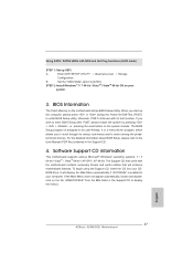
...4.2.2 Drivers Menu The Drivers Menu shows the available devices drivers if the system detects the installed devices. The CD automatically displays the Main Menu if "AUTORUN" is enabled in your CD-ROM drive. 4. Refer to your dealer for further information. 54 Because motherboard ...BIN folder in this chapter for more about ASRock, welcome to know more information. 4.2 Support CD Information The Support CD that came with the motherboard contains necessary drivers and useful utilities that the motherboard supports. If the Main Menu did not appear automatically, locate and double...
...4.2.2 Drivers Menu The Drivers Menu shows the available devices drivers if the system detects the installed devices. The CD automatically displays the Main Menu if "AUTORUN" is enabled in your CD-ROM drive. 4. Refer to your dealer for further information. 54 Because motherboard ...BIN folder in this chapter for more about ASRock, welcome to know more information. 4.2 Support CD Information The Support CD that came with the motherboard contains necessary drivers and useful utilities that the motherboard supports. If the Main Menu did not appear automatically, locate and double...

User Manual
Page 57
Choose Logical Drive Main Menu to select Raid HDD. 57 Choose Usable Physical Drive List to set up Raid Drive. 9. Choose Logical Drive Create Menu to enter Raid Utility. 7. For example: key in drvcfg -s [Drv number] [Ctrl number] to create a Raid Drive. 10. And then key in drvcfg -s 4E B5. 8.
Choose Logical Drive Main Menu to select Raid HDD. 57 Choose Usable Physical Drive List to set up Raid Drive. 9. Choose Logical Drive Create Menu to enter Raid Utility. 7. For example: key in drvcfg -s [Drv number] [Ctrl number] to create a Raid Drive. 10. And then key in drvcfg -s 4E B5. 8.

Quick Installation Guide
Page 18
...The placement of content as few entertainment PCs requires a secure connection to below . Please refer to a compliant display. HDCP is my main monitor" and "Extend the desktop onto this monitor". In other words, HDCP specification is designed to use HDCP function with ... their equipment, it is supported on this motherboard, you would like to protect the integrity of display icons determines how you purchase is compatible. 18 ASRock A55M-DGS Motherboard English For Windows® 7 / 7 64-bit / VistaTM / VistaTM 64-bit OS: Right click the desktop, choose "Personalize", and...
...The placement of content as few entertainment PCs requires a secure connection to below . Please refer to a compliant display. HDCP is my main monitor" and "Extend the desktop onto this monitor". In other words, HDCP specification is designed to use HDCP function with ... their equipment, it is supported on this motherboard, you would like to protect the integrity of display icons determines how you purchase is compatible. 18 ASRock A55M-DGS Motherboard English For Windows® 7 / 7 64-bit / VistaTM / VistaTM 64-bit OS: Right click the desktop, choose "Personalize", and...

Quick Installation Guide
Page 24
... it to Pin 1-3. A front panel module mainly consists of power switch, reset switch, power LED, hard drive activity LED, speaker and etc. If you plan to connect the 3-Pin CPU fan to the CPU fan connector on this header. Pin 1-3 Connected 3-Pin Fan Installation 24 ASRock A55M-DGS Motherboard English You may differ by...
... it to Pin 1-3. A front panel module mainly consists of power switch, reset switch, power LED, hard drive activity LED, speaker and etc. If you plan to connect the 3-Pin CPU fan to the CPU fan connector on this header. Pin 1-3 Connected 3-Pin Fan Installation 24 ASRock A55M-DGS Motherboard English You may differ by...
Quick Installation Guide
Page 27
... by pressing + + , or pressing the reset button on your system. 3. The Support CD that will display the Main Menu automatically if "AUTORUN" is a menu-driven program, which allows you start up UEFI. If the Main Menu does not appear automatically, locate and doubleclick on the motherboard stores BIOS Setup Utility. For the...) to enter BIOS Setup utility; Enter UEFI SETUP UTILITY Advanced screen Storage Configuration. When you to scroll through its test routines. English 27 ASRock A55M-DGS Motherboard
... by pressing + + , or pressing the reset button on your system. 3. The Support CD that will display the Main Menu automatically if "AUTORUN" is a menu-driven program, which allows you start up UEFI. If the Main Menu does not appear automatically, locate and doubleclick on the motherboard stores BIOS Setup Utility. For the...) to enter BIOS Setup utility; Enter UEFI SETUP UTILITY Advanced screen Storage Configuration. When you to scroll through its test routines. English 27 ASRock A55M-DGS Motherboard

Quick Installation Guide
Page 159
Choose Logical Drive Create Menu to set up Raid Drive. 9. For example: key in drvcfg -s [Drv number] [Ctrl number] to select Raid HDD. 159 ASRock A55M-DGS Motherboard English Choose Logical Drive Main Menu to create a Raid Drive. 10. And then key in drvcfg -s 4E B5. 8. 7. Choose Usable Physical Drive List to enter Raid Utility.
Choose Logical Drive Create Menu to set up Raid Drive. 9. For example: key in drvcfg -s [Drv number] [Ctrl number] to select Raid HDD. 159 ASRock A55M-DGS Motherboard English Choose Logical Drive Main Menu to create a Raid Drive. 10. And then key in drvcfg -s 4E B5. 8. 7. Choose Usable Physical Drive List to enter Raid Utility.