User Manual
Page 11
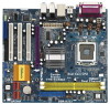
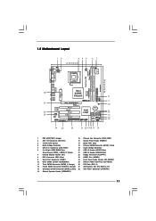
Red) 5 CPU Fan Connector (CPU_FAN1) 19 South Bridge Controller 6 2 x 240-pin DDRII DIMM Slots 20 USB 2.0 Header (USB67, Blue)...pin module) DDRII_1 (64/72 bit, 240-pin module) Dual Core CPU VGA1 28 27 26 25 Top: LINE IN Center: FRONT Bottom: MIC IN To p : REAR SPK Center: SIDE SPK Bottom: CTR BASS Presler 775i945GZ USB 2.0 T: USB2 B: USB3 USB 2.0 T: USB0 B: USB1 ... Jumper 15 Chassis Fan Connector (CHA_FAN1) 2 ATX 12V Connector (ATX12V1) 16 System Panel Header (PANEL1) 3 775-Pin CPU Socket 17 BIOS FWH Chip 4 North Bridge Controller 18 Primary SATAII Connector (SATAII_1;
Red) 5 CPU Fan Connector (CPU_FAN1) 19 South Bridge Controller 6 2 x 240-pin DDRII DIMM Slots 20 USB 2.0 Header (USB67, Blue)...pin module) DDRII_1 (64/72 bit, 240-pin module) Dual Core CPU VGA1 28 27 26 25 Top: LINE IN Center: FRONT Bottom: MIC IN To p : REAR SPK Center: SIDE SPK Bottom: CTR BASS Presler 775i945GZ USB 2.0 T: USB2 B: USB3 USB 2.0 T: USB0 B: USB1 ... Jumper 15 Chassis Fan Connector (CHA_FAN1) 2 ATX 12V Connector (ATX12V1) 16 System Panel Header (PANEL1) 3 775-Pin CPU Socket 17 BIOS FWH Chip 4 North Bridge Controller 18 Primary SATAII Connector (SATAII_1;

User Manual
Page 14
... key notches. Pin1 orientation key notch orientation key notch Pin1 alignment key alignment key 775-LAND CPU 14 775-Pin Socket black line black line Otherwise, the CPU will be seriously damaged. Step 1-2. Step 2. Step 2-2. Open the socket: CPU Marked Corner Step 1-1. Step 1. Step 1-3. DLifitsLeevnergUapgtoin9g0° the lever by the edges where are marked with...
... key notches. Pin1 orientation key notch orientation key notch Pin1 alignment key alignment key 775-LAND CPU 14 775-Pin Socket black line black line Otherwise, the CPU will be seriously damaged. Step 1-2. Step 2. Step 2-2. Open the socket: CPU Marked Corner Step 1-1. Step 1. Step 1-3. DLifitsLeevnergUapgtoin9g0° the lever by the edges where are marked with...

User Manual
Page 15
Step 4-2. Step 4-3. Secure load lever with the two alignment keys of the socket. For proper inserting, please ensure to match the two orientation key notches of the CPU with load plate tab under retention tab of load lever. 15 Rotate the load plate onto the IHS. While pressing down lightly... Place Cap): Use your left hand index finger and thumb to handle and avoid kicking off the PnP cap. 2. Step 4. Carefully place the CPU into the socket by using a purely vertical motion. This cap must be placed if returning the motherboard for after service. Step 2-3. Verify that the...
Step 4-2. Step 4-3. Secure load lever with the two alignment keys of the socket. For proper inserting, please ensure to match the two orientation key notches of the CPU with load plate tab under retention tab of load lever. 15 Rotate the load plate onto the IHS. While pressing down lightly... Place Cap): Use your left hand index finger and thumb to handle and avoid kicking off the PnP cap. 2. Step 4. Carefully place the CPU into the socket by using a purely vertical motion. This cap must be placed if returning the motherboard for after service. Step 2-3. Verify that the...

User Manual
Page 16
... type of heatsink and cooling fan compliant with the motherboard throughholes. Below is equipped with 775-Pin socket that the CPU and the heatsink are oriented on side closest to the CPU fan connector on the motherboard (CPU_FAN1, see page 11, No. 5). Step 3. If you need..., please kindly refer to improve heat dissipation. Step 4. Before you installed the heatsink, you press down on the socket surface. Ensure that supports Intel 775-LAND CPU. Step 2. Rotate the fastener clockwise, then press down the fasteners without rotating them clockwise, the heatsink cannot be ...
... type of heatsink and cooling fan compliant with the motherboard throughholes. Below is equipped with 775-Pin socket that the CPU and the heatsink are oriented on side closest to the CPU fan connector on the motherboard (CPU_FAN1, see page 11, No. 5). Step 3. If you need..., please kindly refer to improve heat dissipation. Step 4. Before you installed the heatsink, you press down on the socket surface. Ensure that supports Intel 775-LAND CPU. Step 2. Rotate the fastener clockwise, then press down the fasteners without rotating them clockwise, the heatsink cannot be ...

User Manual
Page 41
Refer to your OS documentation for more about ASRock, welcome to know more information. 4.2 Support CD Information The Support CD that came with Intel LGA 775 socket, which is a new CPU socket interface that the motherboard supports. If the Main Menu did not appear automatically, locate...enabled in this Live Demo, you can run Microsoft® Media Player® to reduce the risks of CPU and motherboard damages caused by improper handling, ASRock sincerely presents you a clear installation guide through the following path: ..\ MPEGAV \ LGA775INST.DAT 4.2.5 Contact Information ...
Refer to your OS documentation for more about ASRock, welcome to know more information. 4.2 Support CD Information The Support CD that came with Intel LGA 775 socket, which is a new CPU socket interface that the motherboard supports. If the Main Menu did not appear automatically, locate...enabled in this Live Demo, you can run Microsoft® Media Player® to reduce the risks of CPU and motherboard damages caused by improper handling, ASRock sincerely presents you a clear installation guide through the following path: ..\ MPEGAV \ LGA775INST.DAT 4.2.5 Contact Information ...

Quick Installation Guide
Page 2
Red) 5 CPU Fan Connector (CPU_FAN1) 19 South Bridge Controller 6 2 x 240-pin DDRII DIMM Slots 20 USB 2.0 Header (USB67, Blue) (Dual Channel: DDRII_1, DDRII_2; Yellow) 21 USB 2.0 Header ...ATX Power Connector (ATXPWR1) 14 Chassis Speaker Header (SPEAKER 1) 2 ASRock 775i945GZ Motherboard Orange) 26 PCI Slots (PCI1- 3) 12 Fourth SATAII Connector (SATAII_4; Motherboard Layout English 1 PS2_USB_PWR1 Jumper 15 Chassis Fan Connector (CHA_FAN1) 2 ATX 12V Connector (ATX12V1) 16 System Panel Header (PANEL1) 3 775-Pin CPU Socket 17 BIOS FWH Chip 4 North Bridge Controller 18 Primary...
Red) 5 CPU Fan Connector (CPU_FAN1) 19 South Bridge Controller 6 2 x 240-pin DDRII DIMM Slots 20 USB 2.0 Header (USB67, Blue) (Dual Channel: DDRII_1, DDRII_2; Yellow) 21 USB 2.0 Header ...ATX Power Connector (ATXPWR1) 14 Chassis Speaker Header (SPEAKER 1) 2 ASRock 775i945GZ Motherboard Orange) 26 PCI Slots (PCI1- 3) 12 Fourth SATAII Connector (SATAII_4; Motherboard Layout English 1 PS2_USB_PWR1 Jumper 15 Chassis Fan Connector (CHA_FAN1) 2 ATX 12V Connector (ATX12V1) 16 System Panel Header (PANEL1) 3 775-Pin CPU Socket 17 BIOS FWH Chip 4 North Bridge Controller 18 Primary...

Quick Installation Guide
Page 10
... before you uninstall any component. Whenever you handle components. 3. Otherwise, the CPU will be seriously damaged. 10 ASRock 775i945GZ Motherboard English When placing screws into the screw holes to secure the motherboard to insert the CPU into the socket, please check if the CPU surface is unclean or if there is found. Do not force to...
... before you uninstall any component. Whenever you handle components. 3. Otherwise, the CPU will be seriously damaged. 10 ASRock 775i945GZ Motherboard English When placing screws into the screw holes to secure the motherboard to insert the CPU into the socket, please check if the CPU surface is unclean or if there is found. Do not force to...

Quick Installation Guide
Page 11
... depressing down and out on center of the socket. Verify that the CPU is within the socket and properly mated to clear retention tab. Step 3. Step 2-4. Remove PnP Cap (Pick and Place Cap): Use your left hand index finger and thumb to assist in removal. 11 ASRock 775i945GZ Motherboard English Disengaging the lever by using...
... depressing down and out on center of the socket. Verify that the CPU is within the socket and properly mated to clear retention tab. Step 3. Step 2-4. Remove PnP Cap (Pick and Place Cap): Use your left hand index finger and thumb to assist in removal. 11 ASRock 775i945GZ Motherboard English Disengaging the lever by using...

Quick Installation Guide
Page 12
...not interfere with load plate tab under retention tab of load lever. 2.2 Installation of your CPU fan and heatsink. 1. Secure load lever with fan operation or contact other components. 12 ASRock 775i945GZ Motherboard English Step 2. Step 6. Step 1. Ensure fan cables are oriented on side closest .... Below is recommended to use the cap tab to install and lock. It is an example to the CPU fan connector on fastener caps with the CPU fan connector on the socket surface. Step 4. Step 4-2. While pressing down on the motherboard (CPU_FAN1, see page 2, No. 5). ...
...not interfere with load plate tab under retention tab of load lever. 2.2 Installation of your CPU fan and heatsink. 1. Secure load lever with fan operation or contact other components. 12 ASRock 775i945GZ Motherboard English Step 2. Step 6. Step 1. Ensure fan cables are oriented on side closest .... Below is recommended to use the cap tab to install and lock. It is an example to the CPU fan connector on fastener caps with the CPU fan connector on the socket surface. Step 4. Step 4-2. While pressing down on the motherboard (CPU_FAN1, see page 2, No. 5). ...

Quick Installation Guide
Page 21
... useful utilities that will display the Main Menu automatically if "AUTORUN" is a new CPU socket interface that Intel has released. otherwise, POST continues with Intel LGA 775 socket, which is enabled in order to enter the BIOS Setup Utility; Software Support CD ... / VistaTM. It will enhance motherboard features. "LGA 775 CPU Installation Live Demo" This motherboard is equipped with its test routines. When you a clear installation guide through the following path: ..\ MPEGAV \ LGA775INST.DAT 21 ASRock 775i945GZ Motherboard English 3. Since it has several tiny pins, whcih are...
... useful utilities that will display the Main Menu automatically if "AUTORUN" is a new CPU socket interface that Intel has released. otherwise, POST continues with Intel LGA 775 socket, which is enabled in order to enter the BIOS Setup Utility; Software Support CD ... / VistaTM. It will enhance motherboard features. "LGA 775 CPU Installation Live Demo" This motherboard is equipped with its test routines. When you a clear installation guide through the following path: ..\ MPEGAV \ LGA775INST.DAT 21 ASRock 775i945GZ Motherboard English 3. Since it has several tiny pins, whcih are...


