
Command Reference
Page 164
... to be sent, including the global LLDP information and the LLDP information about the LLDP-enabled ports. display lldp local-information Global LLDP local-information: Chassis ID : 000f-e218-d0d1 System name : System System description : System System capabilities supported : Bridge,Router System capabilities enabled : Bridge,Router MED information Device class: Connectivity...
... to be sent, including the global LLDP information and the LLDP information about the LLDP-enabled ports. display lldp local-information Global LLDP local-information: Chassis ID : 000f-e218-d0d1 System name : System System description : System System capabilities supported : Bridge,Router System capabilities enabled : Bridge,Router MED information Device class: Connectivity...

Command Reference
Page 166
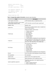
...device System description System description System capabilities supported System capabilities enabled PoE device type Supported capabilities, which can be: z Bridge, indicating switching z Router, indicating routing Currently enabled capabilities, which can be used directly by end users. z Class II, indicating a media ... Table 1-1 display lldp local-information command output description Field Description Global LLDP local-information The global LLDP information Chassis ID ID that are LLDP-enabled are of this type supports IP communication systems of end user. A device of ...
...device System description System description System capabilities supported System capabilities enabled PoE device type Supported capabilities, which can be: z Bridge, indicating switching z Router, indicating routing Currently enabled capabilities, which can be used directly by end users. z Class II, indicating a media ... Table 1-1 display lldp local-information command output description Field Description Global LLDP local-information The global LLDP information Chassis ID ID that are LLDP-enabled are of this type supports IP communication systems of end user. A device of ...

Command Reference
Page 169
... through a port. display lldp neighbor-information LLDP neighbor-information of port 144[GigabitEthernet2/0/48]: Neighbor index : 1 Update time : 0 days,1 hours,45 minutes,4 seconds Chassis type : MAC address Chassis ID : 000f-e22e-972b Port ID type : Interface name Port ID : GigabitEthernet3/0/48 Port description : GigabitEthernet3/0/48 Interface System name : System System description : System...
... through a port. display lldp neighbor-information LLDP neighbor-information of port 144[GigabitEthernet2/0/48]: Neighbor index : 1 Update time : 0 days,1 hours,45 minutes,4 seconds Chassis type : MAC address Chassis ID : 000f-e22e-972b Port ID type : Interface name Port ID : GigabitEthernet3/0/48 Port description : GigabitEthernet3/0/48 Interface System name : System System description : System...
Command Reference
Page 170
... the neighboring device, which can be a MAC address, a network address, an interface or some other value depending on the chassis type. PSE pairs control ability : No Power pairs : Signal Port power classification : Class 0 Link aggregation supported : Yes...-information command output description Field Description LLDP neighbor-information LLDP information about a neighboring device is latest updated. Chassis type Chassis ID Chassis information, which can be: z Chassis component z Interface alias z Port component z MAC address z Network address z Interface name z Locally assigned...
... the neighboring device, which can be a MAC address, a network address, an interface or some other value depending on the chassis type. PSE pairs control ability : No Power pairs : Signal Port power classification : Class 0 Link aggregation supported : Yes...-information command output description Field Description LLDP neighbor-information LLDP information about a neighboring device is latest updated. Chassis type Chassis ID Chassis information, which can be: z Chassis component z Interface alias z Port component z MAC address z Network address z Interface name z Locally assigned...

Getting Started Guide
Page 3
... filters of ports and their related parameters. Introduces pluggable modules for different types of the S7900E Series Ethernet Switches. Conventions The manual uses the following conventions: Command conventions Convention Boldface italic [ ] { x | ...of a command line are grouped in braces and separated by vertical bars. Command arguments are grouped in terms of chassis, SRPUs, LPUs, power supply, and fan tray. Optional alternative items are in Boldface. A minimum of one... be selected. About This Manual Organization 3Com S7900E Family Getting Started Guide is organized...
... filters of ports and their related parameters. Introduces pluggable modules for different types of the S7900E Series Ethernet Switches. Conventions The manual uses the following conventions: Command conventions Convention Boldface italic [ ] { x | ...of a command line are grouped in braces and separated by vertical bars. Command arguments are grouped in terms of chassis, SRPUs, LPUs, power supply, and fan tray. Optional alternative items are in Boldface. A minimum of one... be selected. About This Manual Organization 3Com S7900E Family Getting Started Guide is organized...

Getting Started Guide
Page 6
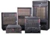
Table of Contents 1 Product Overview 1-1 Introduction 1-1 Physical Description of the S7900E Series 1-1 Chassis and Slots 1-1 Backplane 1-9 Power Supply System 1-9 Fan Tray 1-16 Air Filter 1-16 SRPUs 1-17 SRPU Types 1-17 LSQ1MPUA0 SRPU 1-17 Dedicated ... 1-53 LSQ1TGX2SC0 1-54 LSQ1GP24TSC0 1-55 LSQ1GV40PSC0 1-57 LSQ1PT4PSC0 1-58 LSQ1PT8PSC0 1-59 LSQ1PT16PSC0 1-60 Ordering Information for the S7900E Series 1-61 Purchasing a Switch 1-61 Purchasing SRPUs 1-62 Purchasing LPUs 1-63 Purchasing Optical Modules 1-64 Purchasing Air Filters 1-64 Purchasing Fan Trays 1-64 i
Table of Contents 1 Product Overview 1-1 Introduction 1-1 Physical Description of the S7900E Series 1-1 Chassis and Slots 1-1 Backplane 1-9 Power Supply System 1-9 Fan Tray 1-16 Air Filter 1-16 SRPUs 1-17 SRPU Types 1-17 LSQ1MPUA0 SRPU 1-17 Dedicated ... 1-53 LSQ1TGX2SC0 1-54 LSQ1GP24TSC0 1-55 LSQ1GV40PSC0 1-57 LSQ1PT4PSC0 1-58 LSQ1PT8PSC0 1-59 LSQ1PT16PSC0 1-60 Ordering Information for the S7900E Series 1-61 Purchasing a Switch 1-61 Purchasing SRPUs 1-62 Purchasing LPUs 1-63 Purchasing Optical Modules 1-64 Purchasing Air Filters 1-64 Purchasing Fan Trays 1-64 i

Getting Started Guide
Page 7
...of a card area, a fan area, and a power supply area. The S7900E series are high performance, cost-effective Layer-3 switches with a large capacity. Table 1-2 Dimensions of small- Table 1-1 Dimensions of the S7900E series Model Slot direction Number of slots ...Horizontal 4 S7903E-S Horizontal 3 S7903E Horizontal 5 S7906E Horizontal 8 S7910E Horizontal 12 S7906E-V Vertical 8 Number of SRPU slots 2 half-sized slots 1 2 2 2 2 Physical Description of the S7900E Series Chassis and Slots The integrated chassis of the S7900E series consists of metropolitan area ...
...of a card area, a fan area, and a power supply area. The S7900E series are high performance, cost-effective Layer-3 switches with a large capacity. Table 1-2 Dimensions of small- Table 1-1 Dimensions of the S7900E series Model Slot direction Number of slots ...Horizontal 4 S7903E-S Horizontal 3 S7903E Horizontal 5 S7906E Horizontal 8 S7910E Horizontal 12 S7906E-V Vertical 8 Number of SRPU slots 2 half-sized slots 1 2 2 2 2 Physical Description of the S7900E Series Chassis and Slots The integrated chassis of the S7900E series consists of metropolitan area ...

Getting Started Guide
Page 8
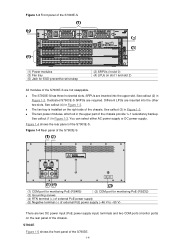
...modules into the other two slots. See callout (3) in Figure 1-1. Figure 1-2 shows the rear panel of the S7902E. z The backplane, switching & routing processing unit (SRPU), power modules, and fan tray are inserted into the upper two slots. SRPUs are all required parts of the... S7900E series. z SRPUs and line processing units (LPUs) are inserted into one S7900E Ethernet switch. z The power supply of the chassis. Different LPUs are distinguished by their edge colors. See callout (4) in Figure 1-1. However, it is installed on the actual ...
...modules into the other two slots. See callout (3) in Figure 1-1. Figure 1-2 shows the rear panel of the S7902E. z The backplane, switching & routing processing unit (SRPU), power modules, and fan tray are inserted into the upper two slots. SRPUs are all required parts of the... S7900E series. z SRPUs and line processing units (LPUs) are inserted into one S7900E Ethernet switch. z The power supply of the chassis. Different LPUs are distinguished by their edge colors. See callout (4) in Figure 1-1. However, it is installed on the actual ...

Getting Started Guide
Page 9
... network cameras connected to their Ethernet ports through twisted pair cables. For details, refer to a power module. S7903E-S Figure 1-3 shows the front panel of the chassis. z For the S7902E and S7903E-S, the external PoE power supply is connected to the PoE power supply input terminals on the rear panel of the...
... network cameras connected to their Ethernet ports through twisted pair cables. For details, refer to a power module. S7903E-S Figure 1-3 shows the front panel of the chassis. z For the S7902E and S7903E-S, the external PoE power supply is connected to the PoE power supply input terminals on the rear panel of the...
Getting Started Guide
Page 10
...Dedicated S7903E-S SRPUs are two DC power input (PoE power supply input) terminals and two COM ports (monitor ports) on the right side of the chassis. Figure 1-4 Rear panel of the S7903E-S (1) COM port for monitoring PoE (RS485) (2) COM port for ESD-preventive wrist strap (2) SRPUs (in...z The two power modules, which sit in Figure 1-3. See callout (3) in the upper part of the chassis provide 1+1 redundancy backup. z The fan tray is installed on the rear panel of the chassis. Figure 1-3 Front panel of the S7903E-S (1) Power modules (3) Fan tray (5) Jack for monitoring PoE...
...Dedicated S7903E-S SRPUs are two DC power input (PoE power supply input) terminals and two COM ports (monitor ports) on the right side of the chassis. Figure 1-4 Rear panel of the S7903E-S (1) COM port for monitoring PoE (RS485) (2) COM port for ESD-preventive wrist strap (2) SRPUs (in...z The two power modules, which sit in Figure 1-3. See callout (3) in the upper part of the chassis provide 1+1 redundancy backup. z The fan tray is installed on the rear panel of the chassis. Figure 1-3 Front panel of the S7903E-S (1) Power modules (3) Fan tray (5) Jack for monitoring PoE...

Getting Started Guide
Page 11
SRPUs are hot swappable. z The fan tray is installed on the right side of the chassis (see callout (4) in Figure 1-5). You can select either AC power supply or DC power supply. Figure 1-5 Front panel of the S7903E (1) (5) (4) (2) (3) (3) (1) Fan ... are required and support active-standby switchover. Different LPUs are inserted into the other three slots (see callout (1) in Figure 1-5). S7906E Figure 1-6 shows the front panel of the chassis (see callout (5) in Figure 1-5). z The S7903E has five horizontal slots. SRPUs are inserted into the upper two slots (see...
SRPUs are hot swappable. z The fan tray is installed on the right side of the chassis (see callout (4) in Figure 1-5). You can select either AC power supply or DC power supply. Figure 1-5 Front panel of the S7903E (1) (5) (4) (2) (3) (3) (1) Fan ... are required and support active-standby switchover. Different LPUs are inserted into the other three slots (see callout (1) in Figure 1-5). S7906E Figure 1-6 shows the front panel of the chassis (see callout (5) in Figure 1-5). z The S7903E has five horizontal slots. SRPUs are inserted into the upper two slots (see...

Getting Started Guide
Page 12
...or DC power supply. S7910E Figure 1-7 shows the front panel of the chassis (see callout (3) in Figure 1-6), provide 1+1 redundancy backup. z The S7906E has eight horizontal slots. SRPUs are hot swappable. Figure 1-6 Front panel of the S7906E (5) (1) (4) (2) (3) (3) (1) Fan tray (3) Power module (5) SRPUs... (in slot 0 and slot 1) (2) Jack for ESD-preventive wrist strap (4) LPUs (in slot 2 to slot 7) All the modules of the chassis (see callout (1) Figure 1-6). z The...
...or DC power supply. S7910E Figure 1-7 shows the front panel of the chassis (see callout (3) in Figure 1-6), provide 1+1 redundancy backup. z The S7906E has eight horizontal slots. SRPUs are hot swappable. Figure 1-6 Front panel of the S7906E (5) (1) (4) (2) (3) (3) (1) Fan tray (3) Power module (5) SRPUs... (in slot 0 and slot 1) (2) Jack for ESD-preventive wrist strap (4) LPUs (in slot 2 to slot 7) All the modules of the chassis (see callout (1) Figure 1-6). z The...

Getting Started Guide
Page 13
... the front panel of the S7906E-V. 1-7 SRPUs are hot swappable. SRPUs are inserted in the other ten slots (see callout (3) in Figure 1-7), provide 1+1 redundancy backup. z The fan tray is installed on the right side of the chassis (see callout (5) in Figure 1-7). You can select either AC ... Different LPUs are inserted in the middle two slots (see callout (1) in Figure 1-7). z The two power modules, which sit in the lower part of the chassis (see callout (4) in Figure 1-7). Figure 1-7 Front panel of the S7910E (1) Fan tray (3) Power module (5) SRPUs (in slot 5 and slot 6) (2) ...
... the front panel of the S7906E-V. 1-7 SRPUs are hot swappable. SRPUs are inserted in the other ten slots (see callout (3) in Figure 1-7), provide 1+1 redundancy backup. z The fan tray is installed on the right side of the chassis (see callout (5) in Figure 1-7). You can select either AC ... Different LPUs are inserted in the middle two slots (see callout (1) in Figure 1-7). z The two power modules, which sit in the lower part of the chassis (see callout (4) in Figure 1-7). Figure 1-7 Front panel of the S7910E (1) Fan tray (3) Power module (5) SRPUs (in slot 5 and slot 6) (2) ...

Getting Started Guide
Page 14
...1) All the modules of the chassis (see callout (3) in Figure 1-8) and the air flows up from the bottom. You can select either AC power supply or DC power supply. 1-8 SRPUs are inserted in the other six slots (see callout (2) in Figure 1-8). z The S7906E-V switch has eight vertical slots. z ...The two power modules, which sit in the lower part of the switch are required and support active-standby switchover. Different LPUs are inserted in the left two slots ...
...1) All the modules of the chassis (see callout (3) in Figure 1-8) and the air flows up from the bottom. You can select either AC power supply or DC power supply. 1-8 SRPUs are inserted in the other six slots (see callout (2) in Figure 1-8). z The S7906E-V switch has eight vertical slots. z ...The two power modules, which sit in the lower part of the switch are required and support active-standby switchover. Different LPUs are inserted in the left two slots ...

Getting Started Guide
Page 15
... support a variety of power modules, as management & control signal exchange between cards z Card hot-swapping z Automatic slot recognition z Automatic chassis type recognition z Distributed power supply to the signal backplane with an internal cable. The S7900E series support a large variety of card types,... and system power consumption of a switch varies with the power switch turned off while the device is also connected to the system. The S7906E-V has two backplanes: signal backplane and power supply backplane. The power supply backplane ...
... support a variety of power modules, as management & control signal exchange between cards z Card hot-swapping z Automatic slot recognition z Automatic chassis type recognition z Distributed power supply to the signal backplane with an internal cable. The S7900E series support a large variety of card types,... and system power consumption of a switch varies with the power switch turned off while the device is also connected to the system. The S7906E-V has two backplanes: signal backplane and power supply backplane. The power supply backplane ...

Getting Started Guide
Page 16
... and Installing a Power Module." Table 1-5 Compatibility matrix between power modules and switch chasses Chassis (right) Power module (below) S7902E PSR320-A Y PSR320-D Y PSR650-A Y PSR650-D Y PSR1400-A N PSR1400-D N PSR2800-ACV N S7903E-S S7903E Y N Y N Y N Y N N Y N Y N Y S7906E N N N N Y Y Y S7906E-V S7910E N N N N N N N N Y Y Y Y Y Y z Y means that the power module cannot be used in the chassis. For how to install power modules and power module adapters, refer to...
... and Installing a Power Module." Table 1-5 Compatibility matrix between power modules and switch chasses Chassis (right) Power module (below) S7902E PSR320-A Y PSR320-D Y PSR650-A Y PSR650-D Y PSR1400-A N PSR1400-D N PSR2800-ACV N S7903E-S S7903E Y N Y N Y N Y N N Y N Y N Y S7906E N N N N Y Y Y S7906E-V S7910E N N N N N N N N Y Y Y Y Y Y z Y means that the power module cannot be used in the chassis. For how to install power modules and power module adapters, refer to...

Getting Started Guide
Page 22
...dissipation of the chassis. 1-16 The fan tray is installed on the upper of the front of the S7900E series. Figure 1-16 Fan tray (for the S7903E) The power consumption of the fan trays for the S7900E series Model S7902E fan tray S7903E-S fan tray S7903E fan tray S7906E fan tray ...recommended to clean the air filter every three months. Since the air flows up from the bottom, air filters for the S7906E-V, different from those for vertical cards. The S7906E-V switch provides chassis for the other models, are installed on the right side of the front of the fan trays for the S7900E series...
...dissipation of the chassis. 1-16 The fan tray is installed on the upper of the front of the S7900E series. Figure 1-16 Fan tray (for the S7903E) The power consumption of the fan trays for the S7900E series Model S7902E fan tray S7903E-S fan tray S7903E fan tray S7906E fan tray ...recommended to clean the air filter every three months. Since the air flows up from the bottom, air filters for the S7906E-V, different from those for vertical cards. The S7906E-V switch provides chassis for the other models, are installed on the right side of the front of the fan trays for the S7900E series...

Getting Started Guide
Page 23
...(1.77 × 7.83 × 13.98 in.) 1-17 The SRPUs in the control and management plane and switching fabric. Table 1-14 SRPUs and their suitable chassis Chassis (right) Engine (below) LSQ1MPUA0 LSQ1CGP24TSC0 LSQ1SRP2XB0 (Salience VI-10GE) LSQ1SRPB0 (Salience VI) LSQ1SRP1CB0 (Salience VI-Turbo)... LSQ1SRPD0 (Salience VI-Plus) LSQ1SRP12GB0 (Salience VI-GE) S7902E S7903ES S7903E S7906E S7910E S7906EV Yes No No...
...(1.77 × 7.83 × 13.98 in.) 1-17 The SRPUs in the control and management plane and switching fabric. Table 1-14 SRPUs and their suitable chassis Chassis (right) Engine (below) LSQ1MPUA0 LSQ1CGP24TSC0 LSQ1SRP2XB0 (Salience VI-10GE) LSQ1SRPB0 (Salience VI) LSQ1SRP1CB0 (Salience VI-Turbo)... LSQ1SRPD0 (Salience VI-Plus) LSQ1SRP12GB0 (Salience VI-GE) S7902E S7903ES S7903E S7906E S7910E S7906EV Yes No No...

Getting Started Guide
Page 24
W: Width of the part inserted into the chassis, instead of that of LSQ1MPUA0 (7) RESET button On-board interfaces z CF card slot The CF card slot can accommodate a standard CF card (Type I or Type ... of the LSQ1MPUA0 (1) CF card interface and CFS LED (2) Console port (3) 10/100Base-TX Ethernet port for local or remote configuration and management of the switch through a dialup configuration z One 10/100Base-TX management Ethernet port 10 W to the other end, excluding the length of the handle. Table 1-16 describes the...
W: Width of the part inserted into the chassis, instead of that of LSQ1MPUA0 (7) RESET button On-board interfaces z CF card slot The CF card slot can accommodate a standard CF card (Type I or Type ... of the LSQ1MPUA0 (1) CF card interface and CFS LED (2) Console port (3) 10/100Base-TX Ethernet port for local or remote configuration and management of the switch through a dialup configuration z One 10/100Base-TX management Ethernet port 10 W to the other end, excluding the length of the handle. Table 1-16 describes the...

Getting Started Guide
Page 69
... by the number of LPU slots in the chassis LSQ1FV48SA0 Determined by the number of LPU slots in the chassis LSQ1GP12EA0 Determined by the number of LPU slots in the chassis LSQ1GP12SC0 Determined by the number of LPU slots in the chassis LSQ1GP24SC0 Determined by the number of LPU slots ... the number of LPU slots provided by the chassis LSQ1T24XGSC0 Determined by the number of LPU slots in the chassis LSQ1TGX1EA0 Determined by the number of LPU slots in the chassis LSQ1TGX2SC0 Determined by the number of LPU slots in the chassis LSQ1GP24TSC0 Determined by the number of LPU slots ...
... by the number of LPU slots in the chassis LSQ1FV48SA0 Determined by the number of LPU slots in the chassis LSQ1GP12EA0 Determined by the number of LPU slots in the chassis LSQ1GP12SC0 Determined by the number of LPU slots in the chassis LSQ1GP24SC0 Determined by the number of LPU slots ... the number of LPU slots provided by the chassis LSQ1T24XGSC0 Determined by the number of LPU slots in the chassis LSQ1TGX1EA0 Determined by the number of LPU slots in the chassis LSQ1TGX2SC0 Determined by the number of LPU slots in the chassis LSQ1GP24TSC0 Determined by the number of LPU slots ...