Owners Manual
Page 312
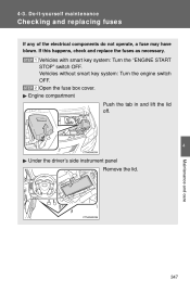
STEP 1 Vehicles with smart key system: Turn the "ENGINE START STOP" switch OFF. STEP 2 Engine compartment 4 Under the driver's side instrument panel Remove the lid. If this happens, check and replace the fuses as necessary. Open the fuse box cover. Push the tab in and lift the lid off. Maintenance and care 347 4 -3 . Vehicles without smart key system: Turn the engine switch OFF. Do-it -yourse lf m a int e na nc e Che ck ing a nd re pla c ing fuse s If any of the electrical components do not operate, a fuse may have blown.
STEP 1 Vehicles with smart key system: Turn the "ENGINE START STOP" switch OFF. STEP 2 Engine compartment 4 Under the driver's side instrument panel Remove the lid. If this happens, check and replace the fuses as necessary. Open the fuse box cover. Push the tab in and lift the lid off. Maintenance and care 347 4 -3 . Vehicles without smart key system: Turn the engine switch OFF. Do-it -yourse lf m a int e na nc e Che ck ing a nd re pla c ing fuse s If any of the electrical components do not operate, a fuse may have blown.

Owners Manual
Page 313
STEP 4 STEP 5 For type A and B fuses: Remove the fuse. 348 STEP 3 After a system failure, see "Fuse layout and amperage ratings" (→P. 351) for details about which fuse to check. Take out the pullout tool. Do-it-yourself maintenance Driver's side instrument panel Remove the instrument panel. Only type A fuse can be removed using the pullout tool. 4-3.
STEP 4 STEP 5 For type A and B fuses: Remove the fuse. 348 STEP 3 After a system failure, see "Fuse layout and amperage ratings" (→P. 351) for details about which fuse to check. Take out the pullout tool. Do-it-yourself maintenance Driver's side instrument panel Remove the instrument panel. Only type A fuse can be removed using the pullout tool. 4-3.

Owners Manual
Page 316
Do-it-yourself maintenance Fuse layout and amperage ratings n Engine compartment Fuse 1 2 3 4 5 CDS FAN RDI FAN ABS NO. 3 ABS NO. 1 HTR Ampere 30 A 40 A 30 A 50 A 50 A Circuit Electric cooling fan(s) 4 Maintenance and care Electric cooling fan(s) .... 2, HTR-IG, WIPER, WASHER, ECU-IG NO. 1, AM1, DOOR, STOP, FR DOOR, POWER, RR DOOR, RL DOOR, OBD, ACC-B, FR FOG, DEF, MIR HTR, TAIL, PANEL Electric power steering 351 6 ALT 120 A 7 EPS 60 A 4-3.
Do-it-yourself maintenance Fuse layout and amperage ratings n Engine compartment Fuse 1 2 3 4 5 CDS FAN RDI FAN ABS NO. 3 ABS NO. 1 HTR Ampere 30 A 40 A 30 A 50 A 50 A Circuit Electric cooling fan(s) 4 Maintenance and care Electric cooling fan(s) .... 2, HTR-IG, WIPER, WASHER, ECU-IG NO. 1, AM1, DOOR, STOP, FR DOOR, POWER, RR DOOR, RL DOOR, OBD, ACC-B, FR FOG, DEF, MIR HTR, TAIL, PANEL Electric power steering 351 6 ALT 120 A 7 EPS 60 A 4-3.

Owners Manual
Page 319
Do-it-yourself maintenance n Under the driver's side instrument panel Fuse 1 2 DEF PWR SEAT Ampere 40 A 30 A Circuit Rear window defogger, MIR HTR Power seat Parking lights, tail lights, license plate lights, front side marker lights, ... system, SRS airbag system, multiport fuel injection system/sequential multiport fuel injection system, front passenger occupant classification system Gauge and meters 3 TAIL 10 A 4 5 6 7 8 9 10 11 PANEL FR DOOR RL DOOR RR DOOR SUNROOF CIG ACC MIR HTR 7.5 A 20 A 20 A 20 A 20 A 15 A 7.5 A 10 A 12 IGN 7.5 A 13 354 METER...
Do-it-yourself maintenance n Under the driver's side instrument panel Fuse 1 2 DEF PWR SEAT Ampere 40 A 30 A Circuit Rear window defogger, MIR HTR Power seat Parking lights, tail lights, license plate lights, front side marker lights, ... system, SRS airbag system, multiport fuel injection system/sequential multiport fuel injection system, front passenger occupant classification system Gauge and meters 3 TAIL 10 A 4 5 6 7 8 9 10 11 PANEL FR DOOR RL DOOR RR DOOR SUNROOF CIG ACC MIR HTR 7.5 A 20 A 20 A 20 A 20 A 15 A 7.5 A 10 A 12 IGN 7.5 A 13 354 METER...


