Other Manual
Page 2
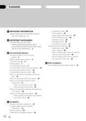
...display 20 - Parts supplied 28 - Installing the hide-away unit 25 - When installing the antenna inside the vehicle (on the body) 30 After Installation After Installing this Navigation System 31 Contents IMPORTANT INFORMATION ABOUT YOUR NEW NAVIGATION SYSTEM AND THIS MANUAL 3 IMPORTANT SAFEGUARDS PLEASE READ ... 12 Connecting the power cord (2) 14 When connecting to rear video output 20 Installation Precautions before connecting the system 5 Before installing this navigation system 22 2 En - When using the AV-1 Input 19 - When installing the antenna outside the vehicle (on the rear...
...display 20 - Parts supplied 28 - Installing the hide-away unit 25 - When installing the antenna inside the vehicle (on the body) 30 After Installation After Installing this Navigation System 31 Contents IMPORTANT INFORMATION ABOUT YOUR NEW NAVIGATION SYSTEM AND THIS MANUAL 3 IMPORTANT SAFEGUARDS PLEASE READ ... 12 Connecting the power cord (2) 14 When connecting to rear video output 20 Installation Precautions before connecting the system 5 Before installing this navigation system 22 2 En - When using the AV-1 Input 19 - When installing the antenna outside the vehicle (on the rear...
Other Manual
Page 7
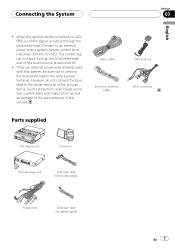
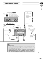
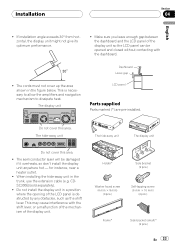
... of the vehicle. 30-pin cable Extension antenna cable GPS antenna RCA connector Parts supplied The display unit Connector The hide-away unit Extension lead (for reverse signal) Power cord Extension lead (for speed signal) En 7 Connecting the System Section 03 English ! When the ignition switch is turned on (ACC ON), a control signal is switched...
... of the vehicle. 30-pin cable Extension antenna cable GPS antenna RCA connector Parts supplied The display unit Connector The hide-away unit Extension lead (for reverse signal) Power cord Extension lead (for speed signal) En 7 Connecting the System Section 03 English ! When the ignition switch is turned on (ACC ON), a control signal is switched...
Other Manual
Page 8
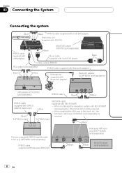
... separately) 8 En GEX-P10XMT) (sold separately) Blue Multi-CD player (sold separately) is required. Section 03 Connecting the System Connecting the system Blue Black IP-BUS cable (supplied with multi-DVD player) Hide-away unit (supplied with XDV-P6) IP-BUS cable (supplied with USB adapter) Black Multi-DVD player (XDV-P6) (sold separately) 25-pin cable (supplied with multi...
... separately) 8 En GEX-P10XMT) (sold separately) Blue Multi-CD player (sold separately) is required. Section 03 Connecting the System Connecting the system Blue Black IP-BUS cable (supplied with multi-DVD player) Hide-away unit (supplied with XDV-P6) IP-BUS cable (supplied with USB adapter) Black Multi-DVD player (XDV-P6) (sold separately) 25-pin cable (supplied with multi...
Other Manual
Page 9
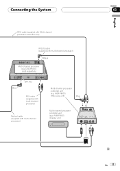
... navigation purposes. The display unit 3 m (9 ft. 10 in.) Black (Extension port) 30-pin cable (supplied) Yellow (VIDEO IN) GPS antenna 5 m (16 ft. 5 in.) Light gray The hide-away unit Blue 3 m (9 ft. 10 in.) Extension antenna cable (supplied) Vehicle antenna Antenna jack Dock connector port Light gray Interface cable for iPod (sold separately). En 9 Connecting the System...
... navigation purposes. The display unit 3 m (9 ft. 10 in.) Black (Extension port) 30-pin cable (supplied) Yellow (VIDEO IN) GPS antenna 5 m (16 ft. 5 in.) Light gray The hide-away unit Blue 3 m (9 ft. 10 in.) Extension antenna cable (supplied) Vehicle antenna Antenna jack Dock connector port Light gray Interface cable for iPod (sold separately). En 9 Connecting the System...
Other Manual
Page 10
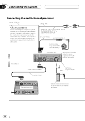
... .) Yellow/Black (GUIDE ON) When combining this navigation system with the multi-channel processor system, connect this navigation system, the audio volume is automatically muted or attenuated. Section 03 Connecting the System Connecting the multi-channel processor 20 cm (7-7/8 in.) 23 cm (9 in .) Light gray (Digital output) Black The hide-away unit Optical cable connection box (supplied with multichannel...
... .) Yellow/Black (GUIDE ON) When combining this navigation system with the multi-channel processor system, connect this navigation system, the audio volume is automatically muted or attenuated. Section 03 Connecting the System Connecting the multi-channel processor 20 cm (7-7/8 in.) 23 cm (9 in .) Light gray (Digital output) Black The hide-away unit Optical cable connection box (supplied with multichannel...
Other Manual
Page 11
DEQ-P8000) (sold separately) Blue OPT.IN 2 RCA cable (supplied with multi-channel processor) Optical cable (supplied with multi-channel processor) Black Multi-channel processor (e.g. Connecting the System RCA cable (supplied with Multi-channel processor controller unit) IP-BUS cable (supplied with multi-channel processor) Multi-channel processor controller unit (e.g. AXM-P8000) (Display unit) English Section 03 En 11 AXM-P8000) (Hide away unit) Blue Multi-channel processor controller unit (e.g.
DEQ-P8000) (sold separately) Blue OPT.IN 2 RCA cable (supplied with multi-channel processor) Optical cable (supplied with multi-channel processor) Black Multi-channel processor (e.g. Connecting the System RCA cable (supplied with Multi-channel processor controller unit) IP-BUS cable (supplied with multi-channel processor) Multi-channel processor controller unit (e.g. AXM-P8000) (Display unit) English Section 03 En 11 AXM-P8000) (Hide away unit) Blue Multi-channel processor controller unit (e.g.
Other Manual
Page 14
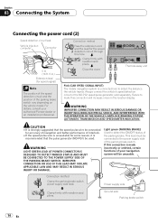
... ND-PG1 speed pulse generator, sold separately. Power supply side Clamp firmly with needle-nosed pliers. The hide-away unit Pink (CAR SPEED SIGNAL INPUT) The mobile navigation system is recommended that the speed pulse wire be connected for some reason, it is connected here to detect... Pioneer dealer or an installation professional. Failure to the power supply side of interlock. • If the speed pulse wire is made incorrectly or omitted, certain functions of the parking brake switch vary depending on the vehicle model. For details, consult your navigation system ...
... ND-PG1 speed pulse generator, sold separately. Power supply side Clamp firmly with needle-nosed pliers. The hide-away unit Pink (CAR SPEED SIGNAL INPUT) The mobile navigation system is recommended that the speed pulse wire be connected for some reason, it is connected here to detect... Pioneer dealer or an installation professional. Failure to the power supply side of interlock. • If the speed pulse wire is made incorrectly or omitted, certain functions of the parking brake switch vary depending on the vehicle model. For details, consult your navigation system ...
Other Manual
Page 18
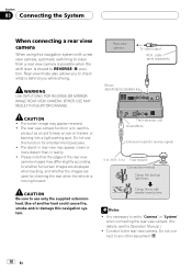
...a rear view camera When using this navigation system with needle-nosed pliers. OTHER USE MAY RESULT IN INJURY OR DAMAGE. It is necessary to set to "Camera" in reality. ! The object in rear view may appear closer or more distant than in "System" when connecting the rear view camera... light lead. The hide-away unit Violet/White Extension lead (for entertainment purposes. ! Clamp firmly with a rear view camera, automatic switching to video from a rear view camera is possible when the shift lever is behind you to check what is moved to use this navigation system. The screen image ...
...a rear view camera When using this navigation system with needle-nosed pliers. OTHER USE MAY RESULT IN INJURY OR DAMAGE. It is necessary to set to "Camera" in reality. ! The object in rear view may appear closer or more distant than in "System" when connecting the rear view camera... light lead. The hide-away unit Violet/White Extension lead (for entertainment purposes. ! Clamp firmly with a rear view camera, automatic switching to video from a rear view camera is possible when the shift lever is behind you to check what is moved to use this navigation system. The screen image ...
Other Manual
Page 19
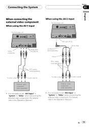
Connecting the System Section 03 English When connecting the external video component When using the AV-1 Input The hide-away unit When using the AV-2 Input The hide-away unit Yellow (VIDEO IN) White, Red (AUDIO IN) CD-RM10 (sold separately) Mini jack (AV 2) White, Red Yellow RCA cables (sold separately) RCA cables (sold separately) ...
Connecting the System Section 03 English When connecting the external video component When using the AV-1 Input The hide-away unit When using the AV-2 Input The hide-away unit Yellow (VIDEO IN) White, Red (AUDIO IN) CD-RM10 (sold separately) Mini jack (AV 2) White, Red Yellow RCA cables (sold separately) RCA cables (sold separately) ...
Other Manual
Page 20
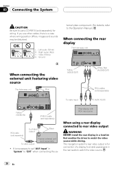
...hide-away unit When connecting the external unit featuring video source The hide-away unit Blue Yellow (VIDEO OUT) White, Red (AUDIO OUT) RCA cables (sold separately) To video input To audio inputs Yellow (VIDEO IN) IP-BUS cable (sold separately) RCA cable (sold separately) To IP-BUS output Black To video output Pioneer external unit... (sold separately) for connection of a display to enable passengers in the rear seats to watch the video source while driving. This navigation system's rear video output is for wiring. Section 03 Connecting the System...
...hide-away unit When connecting the external unit featuring video source The hide-away unit Blue Yellow (VIDEO OUT) White, Red (AUDIO OUT) RCA cables (sold separately) To video input To audio inputs Yellow (VIDEO IN) IP-BUS cable (sold separately) RCA cable (sold separately) To IP-BUS output Black To video output Pioneer external unit... (sold separately) for connection of a display to enable passengers in the rear seats to watch the video source while driving. This navigation system's rear video output is for wiring. Section 03 Connecting the System...
Other Manual
Page 22
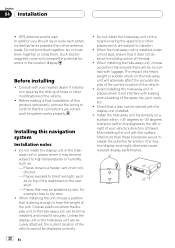
Before making a final installation of this navigation system Installation notes ! Install the hide-away unit horizontally on top of travel). Section 04 Installation ! Installing this product, temporarily connect the wiring to confirm that may become subject to the left ...of the vehicle cannot be firmly installed, and install it may be splashed by rain, for errors in the location display. Unless the display unit or the hide-away unit are securely attached, the current location of a heavy weight or sudden shock on the board covering the spare tire or other places which ...
Before making a final installation of this navigation system Installation notes ! Install the hide-away unit horizontally on top of travel). Section 04 Installation ! Installing this product, temporarily connect the wiring to confirm that may become subject to the left ...of the vehicle cannot be firmly installed, and install it may be splashed by rain, for errors in the location display. Unless the display unit or the hide-away unit are securely attached, the current location of a heavy weight or sudden shock on the board covering the spare tire or other places which ...
Other Manual
Page 23
... the LCD panel is necessary to allow the amplifiers and navigation mechanism to dissipate heat. The hide-away unit The hide-away unit The display unit Do not cover this area. CDSC300E)(sold separately). ! The display unit LCD panel Parts supplied Parts marked (*) are pre-installed. When installing the hide-away unit in the figure below. Do not cover this area. ! If...
... the LCD panel is necessary to allow the amplifiers and navigation mechanism to dissipate heat. The hide-away unit The hide-away unit The display unit Do not cover this area. CDSC300E)(sold separately). ! The display unit LCD panel Parts supplied Parts marked (*) are pre-installed. When installing the hide-away unit in the figure below. Do not cover this area. ! If...
Other Manual
Page 24
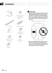
...(2 pcs.) ! The navigation system will be displayed incorrectly. Install with the silk printing side is facing up. Forward/Backward direction of travel or the current location will operate properly only in this position. 24 En Do not install diagonally to install the hide-away unit on the floor with ...the left and right sides of the hide-away unit parallel to your vehicle's direction of travel . Section 04 Installation Side bracket (large) (2 pcs...
...(2 pcs.) ! The navigation system will be displayed incorrectly. Install with the silk printing side is facing up. Forward/Backward direction of travel or the current location will operate properly only in this position. 24 En Do not install diagonally to install the hide-away unit on the floor with ...the left and right sides of the hide-away unit parallel to your vehicle's direction of travel . Section 04 Installation Side bracket (large) (2 pcs...
Other Manual
Page 25
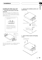
... you can also use the installation board. If the positions of between 4 mm and 4.5 mm in the hide-away unit. Installation Section 04 English Installing the hide-away unit 1 Attach the side brackets to the unit. Washer faced screw (4 mm 8 mm) 3 Secure it firmly using the self-tapping screws. Self-tapping ...screw (6 mm 16 mm) Side bracket When the hide-away unit is installed on the installation position, and drill the holes. Installation board Mark up with the holes in diameter. En 25 Use the...
... you can also use the installation board. If the positions of between 4 mm and 4.5 mm in the hide-away unit. Installation Section 04 English Installing the hide-away unit 1 Attach the side brackets to the unit. Washer faced screw (4 mm 8 mm) 3 Secure it firmly using the self-tapping screws. Self-tapping ...screw (6 mm 16 mm) Side bracket When the hide-away unit is installed on the installation position, and drill the holes. Installation board Mark up with the holes in diameter. En 25 Use the...


