Sony STR-K7100 Support Question
Sony STR-K7100 Support Question
Find answers below for this question about Sony STR-K7100 - Multi Channel Av Receiver.Need a Sony STR-K7100 manual? We have 1 online manual for this item!
Question posted by lindaolmeda on January 15th, 2012
Connection
How can i connect my laptop to the sony str k7100. my laptop has usb and for headset.
Current Answers
Related Sony STR-K7100 Manual Pages
Service Manual - Page 1
HDMI, the HDMI logo and High-Definition Multimedia Interface are trademarks of HDMI Licensing LLC. MULTI CHANNEL AV RECEIVER
9-887-608-01 2007C04-1 © 2007.03
Sony Corporation
Home Audio Division Published by Sony Techno Create Corporation
1 SERVICE MANUAL
Ver. 1.0 2007.03
STR-K7100
US Model
Manufactured under the following conditions:
Area code US
Power requirements 120 V AC, 60 ...
Service Manual - Page 2
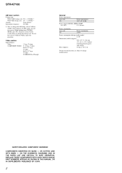
... tuning in any AM station, turn off the receiver. To reset the scale to 9 kHz or 10 kHz. Video section Inputs/Outputs
Video: COMPONENT VIDEO:
1 Vp-p, 75 ohms Y: 1 Vp...SONY.
2 COMPONENTS IDENTIFIED BY MARK 0 OR DOTTED LINE WITH MARK 0 ON THE SCHEMATIC DIAGRAMS AND IN THE PARTS LIST ARE CRITICAL TO SAFE OPERATION. All preset stations will be erased when you change without notice.
STR-K7100...
Service Manual - Page 5
....
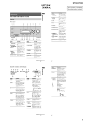
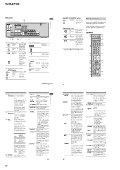
SECTION 1 GENERAL
STR-K7100
This section is decoding DTS signals. Lights up when a memory function, such as Preset Memory (page 54), etc., is selected if -
Getting Started
Description and location of parts
Receiver
Front panel
12
3
4 5 67
8
? / 1
SPEAKERS (OFF/A/B/A+B)
AUTO CAL MIC
PHONES
VIDEO 3 IN/PORTABLE AV IN
VIDEO
L AUDIO R
MULTI CHANNEL DECODING
DISPLAY
INPUT MODE...
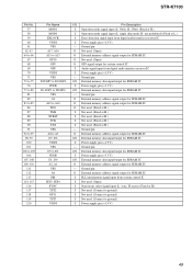
Service Manual - Page 6
...
1 2
3
AUX DMPORT
RECEIVER
4
2CH A.F.D. select preset channels of the VCR, CD player, VCD player, LD player, MD deck, DAT deck, tape deck, satellite tuner, Blu-ray disc recorder or PSX.
B COMPONENT VIDEO INPUT/ OUTPUT section
Green Blue Red
COMPONENT Connects to scan a station.
F D. Remote commander
You can program the remote to control non-Sony components following the...
Service Manual - Page 7
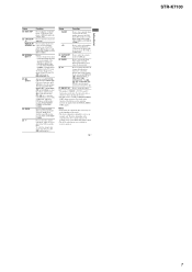
... serve as references when operating the receiver.
Press to select the channel entry mode, either one or two digit of the CD player, VCD player, LD player, MD deck, tape deck, TV, VCR or satellite tuner.
Press to select the category for receiver operation.
13US
Getting Started
STR-K7100
7 a)The number 5, PRESET +, TV CH + and...
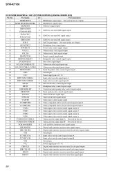
Service Manual - Page 12
....
Afterward, press the [TUNING MODE] to turn on the main power. STR-K7100
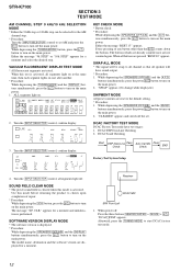
SECTION 3 TEST MODE
AM CHANNEL STEP 9 kHz/10 kHz SELECTION MODE * Either the 9 kHz step or 10 kHz step...board Checking
Start
DSP Data Line Pass Check
Auto Cal Mic Pass Check
END
Factory Test System Setup
4. Receiver
DCAC MIC
SPK Front Left 1.
Either the message "REST 13" appears. SWAP ALL MODE * The ...
Service Manual - Page 13
... "coaxial cable" to connect SG and the set . (2) Input the following signal from front left speaker of A, B and C are detected and automatic scanning stops. The stop of test tone)
STR-K7100 SECTION 4 FM TUNER CHECK
FM AUTO STOP CHECK (1) Turn on loudness of automatic scanning means "The station signal is received in good condition...
Service Manual - Page 17
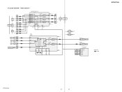
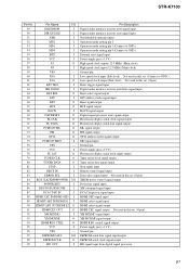
...
PB/CB
-9 PR/CR
VIDEO 1 DVD SAT
-1 J201 (1/2) VIDEO
IN
-2 J200 (1/2) VIDEO
IN
-1 VIDEO
IN
VIDEO 3 IN/ PORTABLE AV IN
J298 (1/2) -1
VIDEO
COMPONENT VIDEO SELECT IC304
1 CH1 IN1 3 CH1 IN2 5 CH1 IN3 7 CH2 IN1 9 CH2 IN2 11 CH2 IN3 16 CH3 IN1 14 CH3 IN2...V COMP SW2 28 V MUTE 34 V_SW1 33 V_SW2 32 V_SW3 31 V_SW4
• Signal path : VIDEO
STR-K7100
STR-K7100
17
17 VIDEO SECTION - 5-4.
Service Manual - Page 20
... X0
97 EEPROM DATA 98 EEPROM CLK
FL_LAT 78 FL_DATA 71
FL_CLK 70
SIRCS IN 82
TUNER/AUDIO SECTION (Page 15)
F
C LINK RX C LINK TX
CNS504
9
8
FLASH
1
PROGRAMMING ...SIGNAL RECEIVER
IC103
2
RV102
3
MASTER VOLUME
F1
FL101
F2
VACUUM
FLUORESCENT
DISPLAY
LED DRIVER
Q110
D105
MULTI CHANNEL DECODING
2
RV101
3
INPUT SELECTOR
SW NETWORK S101-108
SW NETWORK S109-112,115
STR-K7100
20...
Service Manual - Page 22
... are critical for safety.
C
Q
These are indicated. F : TUNER (FM/AM) L : VIDEO (AUDIO) I : VIDEO J : DVD (DIGITAL) c : CD (ANALOG)
for electrolytics and tantalums. • All resistors are... the component side.
• f : internal component.
•
: Pattern from the
(Side B)
pattern face are omitted. DIGITAL Board -
1 IC1301 qd (CKOUT)
5 IC1501 qs (MCLK2)
-
STR-K7100
THIS ...
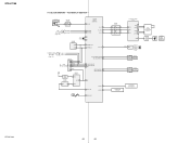
Service Manual - Page 28
...DI
0
DOUT
3.3
ERROR
3.4
BPSYNC
AUTO_VREF
DGND
IC1301
DGND
3.3
DVDD
LC89056W-E DIGITAL AUDIO INTERFACE RECEIVER
DVDD
3.3
1.6 R_SDIN
F3/P3/C3_VF/DATA02
3 VIN_AGND
F2/P2/C2_F2/DLMP
3 LPF... B-2 B-3 B-4 B-5 B-13 B-7 B-10 B-9 B-11 B-12
L
STR-K7100
3
DIGITAL BOARD (3/3)
(Page 30)
28
28 SCHEMATIC DIAGRAM - STR-K7100
• Refer to page 22 for Waveforms. • Refer to page ...
Service Manual - Page 31
... IC804 IC807
D-9 E-12 F-9 F-11
STR-K7100
31
31 STR-K7100
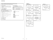
5-17. VIDEO SECTION - • Refer to page 14 for Circuit Boards Location.
: Uses unleaded solder.
1
2
3
4
5
6
7
8
9
10
11
A
SAT IN
J200
SAT
DVD
J201
-1
VIDEO 1
MONITOR
VIDEO IN
VIDEO IN
VIDEO OUT
VIDEO IN
VIDEO OUT
-2
-1
-2
-3
-1
-2
-3
B
12
13
14
J301 COMPONENT VIDEO
DVD IN
VIDEO 1 IN...
Service Manual - Page 32
...R-CH
(Page 24)
MAIN
VIDEO 3 IN/ PORTABLE AV IN
-2
L
L
C299
R299
2 GND 3 L-CH
F BOARD (1/2) CNP503
220p
1k
4 GND
AUDIO
-3
R
R
C298 220p
R298 1k
5 VIDEO3 CN202...
0
CH3IN3
J302 3P
YY
-1
E
Pb
MONITOR OUT PB /CB
-2
Pr PR /CR
-3
COMPONENT VIDEO
J301 9P
F
Pr -9
PR /CR
VIDEO 1 IN
Pb -8 PB /CB
-7 YY
...STR-K7100
STR-K7100
1 3 4 5 6 7
1 2 3 4 5 6 7 8 9 10 11 12 13
G
...
Service Manual - Page 38
...R109
R108
S111 TUNING MODE
S110 - Location
D105
E-5
IC100 C-4 IC101 C-6 IC103 C-8
Q110
D-8
STR-K7100
38
38 STR-K7100
5-25.
S109
TUNING
+
R107
R106
S108 2CH
S107 A.F.D. No. R105
S106 MOVIE
S105 MUSIC...JW119
R120 JW154
JW115 JW149
5
2
Q110 BE
S104 DISPLAY
JW111 R122 R131
D105 MULTI CHANNEL DECODING
R197
E
JW128 C164
JW132
10
11
12
13
14
R104 R102
JW146 ...
Service Manual - Page 48
...A/D converter IC
30
SDI2
I Audio IF data input from system control IC
3
EXTIN
I Not used. (Connect to SDO4
O Digital audio serial data output for 6CH D/A...
- STR-K7100
• IC Pin Descriptions IC1501 CXD9718BQ (DIGITAL SIGNAL PROCESSOR) (DIGITAL BOARD (1/3))
Pin No. Ground pin
22
KFSIO
I/O Audio clock signal (384fs/256fs) input/output for digital audio interface receiver IC
...
Service Manual - Page 49
... SDRAM IC
I PLL initialization signal input from digital audio interface receiver IC
I Power supply pin (+1.9 V)
- Ground pin
...Connect to D2 VDDE D1, D0 A2, A1 VSS A0 PM SDI3, SDI4 SYNC TST2 GP11 TST3 VDDI
I/O
Pin Description
I Operation mode signal input (L: 386fs, H: 256fs) (Fixed at H.)
I Operation mode signal input (L: single chip mode, H: use prohibited) (Fixed at H.)
- STR-K7100...
Service Manual - Page 50
STR-K7100...mute control signal output
29
V COMP SW2
O Video component select switch control signal output 2
30
V COMP SW1
O Video component select switch control signal output 1
31
V SW4
...converters reset signal output
38
DIR XMODE
O Digital audio interface receiver reset signal output
39
DIR CLK SEL
O Digital audio interface receiver serial clock select signal output
40
VSS
- Pin...
Service Manual - Page 51
STR-K7100
Pin No. Pin Name
I/O
49
DIR ERROR
I
50
DIR XSTATE
I
51
NMI
I
52
MD2
...HD OUT
I
Pin Description Digital audio interface receiver error signal input Digital audio interface receiver state signal input Non Maskable interrupt input Operation mode setting pin 2 Operation mode setting pin 1 (Connect to GND.) Operation mode setting pin 0 (Connect to GND.) External reset signal ...
Service Manual - Page 64
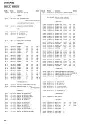
No. STR-K7100
DISPLAY HDMI SW
Ref. No. Part No.
Description
CNS100 1-784-778-11 CONNECTOR, FFC 17P
Remark
< DIODE >
D105 6-501-539-01 LED SELK5E20C-DTP15 (MULTI CHANNEL DECODING)
< VACUUM FLUORESCENT DISPLAY >
FL101 1-519-927-11 VACUUM FLUORESCENT DISPLAY
< IC >
IC100 IC101 IC103
8-759-643-83 IC uPD16315GB-3BS 8-759-243-51 IC ...
Service Manual - Page 70

... IN, MONITOR VIDEO OUT)
J301 1-816-592-11 JACK, PIN 9P (COMPONENT VIDEO SAT IN,DVD IN,VIDEO 1 IN)
J302 1-815-360-11 JACK, PIN 3P (COMPONENT VIDEO MONITOR OUT)
< RESISTOR >
R200 R201 R218 R219 R220
1-247-804... CONNECTOR)
< JACK >
J298 1-819-187-11 JACK, PIN 3P (VIDEO 3 IN/PORTABLE AV IN VIDEO,AUDIO)
70 Description < TRANSISTOR >
Remark Ref. STR-K7100
STANDBY VIDEO VIDEO 3
Ref.
Part No.
Similar Questions

All Lines Connected, No Sound, Display Reads 'unlock'.
never programed system lock but, display reads "UNLOCK" and no sound comes thru speakers. Mode selec...
never programed system lock but, display reads "UNLOCK" and no sound comes thru speakers. Mode selec...
(Posted by rvcampbell 7 years ago)

Sony Multi Channel Av Receiver Str-dg800
Where can I fond the ON/OFF power button for the Sony Multi Channel AV Receiver STR-DG800?
Where can I fond the ON/OFF power button for the Sony Multi Channel AV Receiver STR-DG800?
(Posted by denverliverpool 7 years ago)

How To Connect To Laptop Sony Multi Channel Av Receiver Str-k7100
(Posted by Tiadrober 9 years ago)

How To Connect Wii To Sony Multi Channel Av Receiver Str-dh520
(Posted by DswaWom 10 years ago)

How To Connect A Ps3 To A Sony Str K7100
(Posted by pebart4 10 years ago)