Icom IC-7410 Support Question
Icom IC-7410 Support Question
Find answers below for this question about Icom IC-7410.Need a Icom IC-7410 manual? We have 2 online manuals for this item!
Question posted by andythebrave on November 5th, 2022
Icom8410 Folding Back Power
icom7410 folding back power could ot be rf alc circuit. Have order new caps on 741p but a antennas seem out on swr
Current Answers
Answer #1: Posted by SonuKumar on November 6th, 2022 1:51 AM
SonuKumar

Member since:
May 9th, 2021 Points: 16,619,300

Member since:
May 9th, 2021 Points: 16,619,300
https://www.manualslib.com/manual/851768/Icom-Ic-7410.html
please follow service manual
Please respond to my effort to provide you with the best possible solution by using the "Acceptable Solution" and/or the "Helpful" buttons when the answer has proven to be helpful.
Regards,
Sonu
Your search handyman for all e-support needs!!
Related Icom IC-7410 Manual Pages
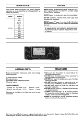
Instruction Manual - Page 2
...Reorient or relocate the receiving antenna.
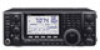
• Increase the...order intercept point (IP3) of +30 dBm (HF bands only)
❍ Simple band scope function ❍ ±0.5 ppm of your IC-7410. q Hand microphone 1
w DC power cable 1
e Spare fuse (ATC 5 A 1
r Spare fuse (ATC 30 A 2
t ACC cable 1
y 6.3 (d) mm plug 1
* Differs depending on a
circuit... the IC-7410 your radio of ...
Instruction Manual - Page 3

...RF VOLTAGE!
NEVER operate the transceiver
with wet hands.
NEVER apply AC power to the
[DC13.8V] socket on the rear panel.
NEVER apply more than the linear amplifier's maximum input level, otherwise, the linear amplifier will become hot
when operating the transceiver continuously for transmitter circuits...attach an antenna or internal antenna connector ... to the IC-7410 may cause injury...
Instruction Manual - Page 4

...antenna tuner connection 18 D Connecting the AH-4 18 ■ Power supply connections 19 ■ Connecting to a DC power supply 19 D Connecting to the PS-126 DC POWER
SUPPLY 19 D Connecting to a non-Icom DC POWER
SUPPLY 19 ■ Linear amplifier connections 20 D Connecting the IC...setting 31 ■ Squelch and receive (RF) sensitivity 32 ■ Voice synthesizer operation ...
Instruction Manual - Page 9

...-receive switching delay time for the Semi Break-in the SSB or AM modes, the ALC meter swings within the ALC zone. Decreases
Increases
1 2 3 4 5 6 7 8 9 10 11 12 13...(maximum). Short delay for high speed keying
Long delay for Icom microphones
Decreases
Increases
!2 R F POWER CONTROL [RF PWR] (outer control;
Decreases
Increases
!6 M ONITOR GAIN CONTROL [MONI GAIN] (p. 65) ...
Instruction Manual - Page 15
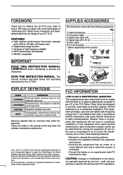
...-259 plug con- on the IC-7410
automatically changes those settings on the front panel. (p. 1) (+)
7
8
(_)
9
w TUNER CONTROL SOCKET [TUNER] (p. 18) Connect the control cable from an optional AH-4 hf/
50 mhz automatic antenna tuner. r ANTENNA CONNECTOR 1 [ANT1] (p. 16)
o ACCESSORY SOCKET [ACC]
13
t ANTENNA CONNECTOR 2 [ANT2] (p. 16) Connect a 50 ø antenna with another Icom
16 17...
Instruction Manual - Page 22
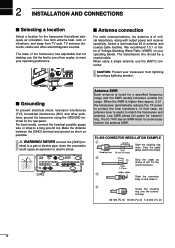
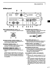
...power to match the transceiver and antenna.
minal to meet your operating bands. Strip the cable jacket and tin the shield.
The IC-7410 has an SWR meter to a long ground rod. Select a well-matched 50 ø antenna...
Antenna SWR
Each antenna is of Voltage Standing Wave Ratio (VSWR) on your operating preference.
■ Antenna connection
For radio communications, the antenna ...
Instruction Manual - Page 28
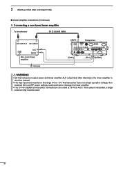
... level after referring to -3 V. The transceiver does not accept a positive voltage. Nonmatched ALC and RF power settings could overheat or damage the linear amplifier.
• T he ALC input level must be in the range 0 V to the linear amplifier instruction manual.
• T he IC-7410 SEND terminal (ACC connector pin 3) is exceeded, a larger external relay must be...
Instruction Manual - Page 40
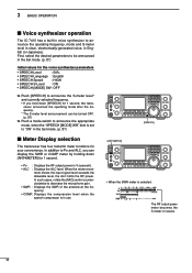
... exceeds the allowable level, the ALC limits the RF power. 3 BASIC OPERATION
■ Voice synthesizer operation
The IC-7410 has a built-in voice synthesizer...ALC : Displays the ALC level. The RF output power meter becomes the S-meter in English (or Japanese). In such cases, rotate the [MIC] control counterclockwise to decrease the microphone gain. • SWR : Displays the SWR of the antenna...
Instruction Manual - Page 41

... transmit output power ➥ Rotate [RF PWR].
&#...8226; Adjustable range : 2 W to 100 W (2 W to 27 W in use?" once or twice, before you begin operating on the transceiver). • The TX indicator lights red.
It's good amateur practice to transmit (or [TRANSMIT] on that the ALC meter reading stays within the ALC zone.
D Transmitting CAUTION: Transmitting without an antenna...
Instruction Manual - Page 61
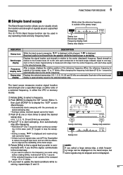
... " " is relative to the S-meter level, S1 to S9, with each vertical dot in the normal way. • If you want to return to the frequency you were using before rotating [DIAL], hold down ...from the speaker while the band scope is approximately equal to the selected sweep step. The IC-7410's Band Scope function can be displayed on either side of the reference frequency. Displays the signal...
Instruction Manual - Page 75
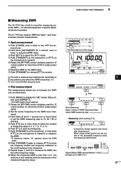
... display the "M2" screen (Menu 2), then push [SWR](F-3). • The SWR graph screen appears. y Read the SWR on
the microphone to select the number of output power (30%).
t P ush [F-3] one or more times to transmit. When measurement points are necessary.
y Push [F-1] to receive.
The IC-7410 can measure SWR two ways- D Plot measurement
Plot measurement allows you to...
Instruction Manual - Page 90

... manually tune.
[TUNER]
❍ If the tuner cannot tune the antenna, check the following : • try again:
• the correct antenna connector selection. • the antenna connection and feedline. • the untuned antenna SWR. (Less than 2.5:1 for the 50 MHz band) • the transmit power. (8 W for the HF bands; 15 W for
the 50 MHz band) •...
Instruction Manual - Page 91

... the SWR is high, and is controlled in the Set mode. (p. 86). • The tuner may not be activated if the TX power output
...antenna tuner starts when [PTT] is pushed on a new frequency that in the IC-PW1/EURO, tune when the internal tuner is ON.
■ Optional external tuner operation
• AH-4 HF/50 MHz AUTOMATIC ANTENNA TUNER The optional AH-4 matches the IC-7410 to a long wire antenna...
Instruction Manual - Page 101
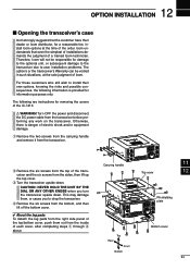
...the transceiver upside down . The following information is danger of electric shock and/or equipment damage. Turn OFF the power and disconnect the DC power cable from the inside of each cover, after completing steps q through r above.
Carrying handle
Top Rear
Front ... provided for removing the covers of the IC-7410. Therefore, Icom will not be voided in such situations, at the time of the...
Instruction Manual - Page 105
...RF/SQL]
[∫] [√]
[PBT-CLR]
[MENU] [SSB] [P.AMP÷ATT] [DIAL] [RIT] [∂TX]
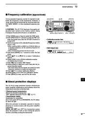
• Calibration marker item
SET C a l i b r a t i o n M a r k e r
Ù 47 Ú
OFF
• REF Adjust item
SET R E F A d j u s t Ù 48 Ú
50%
■ About protection displays
The IC-7410 2-step protection function monitors the power...the stand-by receiving radio station WWV, WWVH...
Instruction Manual - Page 106
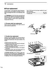
..., the 13.8 V DC from the DC power cable is danger of the problem, and repair it . Otherwise, there is applied to all units in the IC-7410, through the circuitry fuse. This fuse is located in the diagram
to their original position. Then replace the damaged fuse with a new, adequately rated fuse. R WARNING! D Circuitry...
Instruction Manual - Page 120
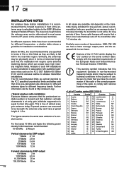
... of the IC-7410 which can be physically short in terms of electrical length and that the installation will require that a timer circuit automatically cuts off the transmitter after 1-2 minutes etc. This warning symbol indicates that this radio, to main lobe gain). Analysis of such MF installations is true of almost every gain antenna today...
Instruction Manual - Page 121
...of equipment: HF/50 MHz TRANSCEIVER
Type-designation: iC- 7410
Version (where applicable): This compliance is based on...(September 2000) iv) EN 60950-1 2006 A11:2009 v) vi)
Bad Soden 14th Jan. 2011 Place and date of the Radio and Telecommunications Terminal Equipment Directive, 1999/5/EC, and that any applicable Essential Test Suite measurements have been performed.
Furukawa General Manager
...
Service Manual - Page 2
...
This service manual describes the latest technical information for a long time when the transceiver is defective.
6. DO NOT apply an RF signal of the power supply when connecting the transceiver. MODEL IC-7410
VERSION
USA EUR EUR-01 ITR ESP TPE KOR CHN FRA EXP
CAUTION
NEVER connect the transceiver to an AC outlet...
Service Manual - Page 15

... from the power AMP (Q241, Q242) is passed through one of LPFs, depending on the CTRL UNIT, before being applied to the antenna connector [ANT1] or [ANT2].
REACTANCE DETECTION CIRCUIT The TX ... P
AMP
IC31
SWR
FOR/REF AMP
DET
D11/D12
CTRL UNIT
ANTENNA TUNING AND SWITCHING CIRCUITS (CTRL UNIT) The TX signal from the PA-A UNIT is passed through 4 detection circuits on the transmitting ...
Similar Questions

Low Power Output
when on full power, the radio only produces about 60 watts on cw.
when on full power, the radio only produces about 60 watts on cw.
(Posted by skyppe2000 11 months ago)

Ic7410 Monitor Inaudible
The monitor on my IC7410 does not seem to work on SSB. I get plenty of sidetone on CW, but cannot he...
The monitor on my IC7410 does not seem to work on SSB. I get plenty of sidetone on CW, but cannot he...
(Posted by michaelagburch 11 months ago)

Mauque Manifeste De Puissance 0 Mon Trasceiver Iv 7200
Sur charge fictive en CW l'appareil délivre seulement 50 W au lieu de 100 et l'indicateur ALC m...
Sur charge fictive en CW l'appareil délivre seulement 50 W au lieu de 100 et l'indicateur ALC m...
(Posted by baudauxguy 1 year ago)

How To Fix An Ic-2300h With Power Output Drops After 3 Seconds Of Transmit.
After adjusting power output using cable jig this problem occured and I can't revert to the previous...
After adjusting power output using cable jig this problem occured and I can't revert to the previous...
(Posted by hpberioso 1 year ago)

Icom 7410
What year was my icom 7410 manufactured, serial number 04001434, and what issues could i expect to h...
What year was my icom 7410 manufactured, serial number 04001434, and what issues could i expect to h...
(Posted by johnmatthew3 5 years ago)