Dell OptiPlex 9010 AIO Support Question
Dell OptiPlex 9010 AIO Support Question
Find answers below for this question about Dell OptiPlex 9010 AIO.Need a Dell OptiPlex 9010 AIO manual? We have 4 online manuals for this item!
Question posted by masWi on May 31st, 2014
How To Remove Optiplex 9010 Back Cover
The person who posted this question about this Dell product did not include a detailed explanation. Please use the "Request More Information" button to the right if more details would help you to answer this question.
Current Answers
Related Dell OptiPlex 9010 AIO Manual Pages
User Manual - Page 1
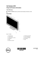
... drive (optional)
7. power button 11. microphones (2) 2. camera privacy cover slider 4. display 6. on screen display keys 9. stand
Regulatory Model: W04C Regulatory Type: W04C001
2012 - 03 optical drive eject button 8. camera (optional) 3. hard-drive activity light 10.
Front View
Figure 1. Dell Optiplex 9010
Setup And Features Information
About Warnings
WARNING: A WARNING...
Owner's Manual - Page 1

Dell OptiPlex 9010 All-In-One Owner's Manual
Regulatory Model: W04C Regulatory Type: W04C001
Owner's Manual - Page 3
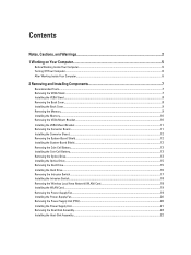
... Inside Your Computer...5 Turning Off Your Computer...6 After Working Inside Your Computer...6
2 Removing and Installing Components 7
Recommended Tools...7 Removing the VESA Stand...7 Installing the VESA Stand...8 Removing the Back Cover...8 Installing the Back Cover...9 Removing the Memory...9 Installing the Memory...10 Removing the VESA Mount Bracket...10 Installing the VESA Mount Bracket...11...
Owner's Manual - Page 5
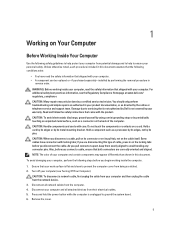
..., first unplug the cable from your computer and all network cables from the computer. 4. Remove the cover.
5 Unless otherwise noted, each procedure included in this document assumes that the following conditions ... may only be replaced or--if purchased separately--installed by performing the removal procedure in
reverse order. You should only perform troubleshooting and simple repairs...
Owner's Manual - Page 7
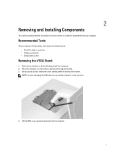
...: • Small flat-blade screwdriver • Phillips screwdriver • Small plastic scribe
Removing the VESA Stand
1. Lift the VESA cover upwards and away from your computer. Place the computer on how to remove or install the components from the computer.
7
2
Removing and Installing Components
This section provides detailed information on a flat surface, display side...
Owner's Manual - Page 8

... stand. 3. Align and place the VESA stand on the computer, till it clicks into place. 4. 5. Remove the screws that secure the VESA stand to the computer. 3. Follow the procedures inBefore Working Inside Your Computer. 2.
Removing the Back Cover
1. Tighten the screws to secure the VESA stand to the computer and lift the VESA...
Owner's Manual - Page 9
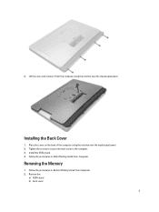
... from the computer using the notches near the input/output panel. Installing the Back Cover
1.
Tighten the screws to secure the back cover to the computer. 3. Follow the procedures in After Working Inside Your Computer. Removing the Memory
1. Remove the:
a) VESA stand b) back cover
9
Follow the procedures in Before Working Inside Your Computer. 2. Place the...
Owner's Manual - Page 10
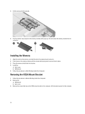
... memory module until the release tabs spring back to the computer. Align the notch on the memory module until it pops up. Install the:
a) back cover b) VESA stand 5.
Removing the VESA Mount Bracket
1. Pry the retention clips away from its place. 4. Press down on the memory-card with the tab in place...
Owner's Manual - Page 11

... converter board. Align and place the bracket on the back of the computer. 2.
Follow the procedures in After Working Inside Your Computer. Install the:
a) back cover b) VESA stand 4. Tighten the screws to secure the VESA mount bracket to the computer. Disconnect the backlight and converter cables from the computer.
11 Installing...
Owner's Manual - Page 12
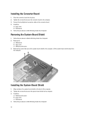
... system-board shield away from the computer.
Align and place the system-board shield on the back of the computer. 2. Removing the System-Board Shield
1. Installing the System-Board Shield
1. Install the:
a) back cover b) VESA stand 5. Follow the procedures in After Working Inside Your Computer.
12 Install the:
a) VESA mount bracket b) back...
Owner's Manual - Page 13
... procedures in Before Working Inside Your Computer. 2. Follow the procedures in Before Working Inside Your Computer. 2. Remove the:
a) VESA stand b) back cover c) system-board shield 3. Place the coin-cell battery into place and secures it. 3.
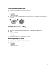
Removing the Coin-Cell Battery
1. Installing the Coin-Cell Battery
1. Follow the procedures in After Working Inside Your...
Owner's Manual - Page 15
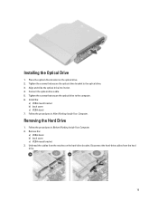
... the screws that secure the optical-drive bracket to the computer. 6. Install the:
a) VESA mount bracket b) back cover c) VESA stand 7. Follow the procedures in After Working Inside Your Computer. Connect the optical-drive cable. 5. Removing the Hard Drive
1. Follow the procedures in Before Working Inside Your Computer. 2. Place the optical-drive bracket...
Owner's Manual - Page 17

... connector on the computer.
4. Follow the procedures in After Working Inside Your Computer. a) VESA mount bracket b) back cover c) VESA stand 6. Unthread the cable from the computer.
17 Follow the procedures in Before Working Inside Your Computer. 2. Remove the screws that secure the intrusion switch to the chassis. Lift the intrusion switch and...
Owner's Manual - Page 18

... stand 4. Follow the procedures in Before Working Inside Your Computer. 2. Disconnect the WLAN cables. Removing the Wireless Local Area Network (WLAN) Card
1. Remove the:
a) VESA stand b) back cover c) VESA mount bracket d) system-board shield 3. Remove the screws that secure the WLAN card to the chassis. 2. Thread the cable along the notches on the chassis...
Owner's Manual - Page 19

... fan bracket away from the computer.
19 Install:
a) system-board shield b) VESA mount bracket c) back cover d) VESA stand 5. Follow the procedures in Before Working Inside Your Computer. 2. Follow the procedures in After Working Inside Your Computer. Remove the screws that secures the fan bracket to the chassis. Tighten the screws to secure...
Owner's Manual - Page 21

Connect the power-supply cable to the connector on the computer. 2. Remove the screws securing the power supply unit to the chassis. 3. Place the power supply unit... Install:
a) power-supply fan b) input/output board shield c) system-board shield d) VESA mount bracket e) back cover f) VESA stand
21 Lift the PSU up and remove it from the computer. 4. Installing the Power Supply Unit
1.
Owner's Manual - Page 22

...module to the chassis. 3. 6. Follow the procedures in After Working Inside Your Computer. Removing the Input/Output Board Shield
1. Remove the:
a) VESA stand b) back cover c) VESA mount bracket d) system-board shield e) power-supply fan 3.
Install:
a) system-board shield b) VESA mount bracket c) back cover d) VESA stand 4. Follow the procedures in Before Working Inside Your Computer...
VESA Tech Sheet - Page 1
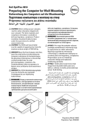
... im Beisein eines zertifizierten Servicetechnikers erfolgen. VORSICHT: Der VESA-Wandbefestigungshalter muss das Vierfache des maximalen Produktgewichts von 19,83 lb/9 kg halten können. Dell OptiPlex 9010
Preparing the Computer for Wall Mounting
Vorbereitung des Computers auf die Wandmontage
Priprema računara za zidnu montažu
CAUTION: Before setting up your...
Statement of Volatility - Page 1
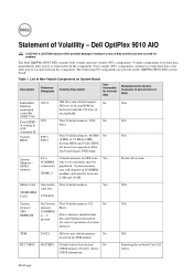
...their data even after power is removed from the component. List of data)
Embedded O2U1
96K bytes non-volatile memory. Removing the on the OptiPlex 9010 AIO system board. Statement of system
memory...Yes
SODIMM One to prevent loss of Non-Volatile Components on -chip RAM. Dell OptiPlex 9010 AIO
CAUTION: A CAUTION indicates either potential damage to hardware or loss of
controller
on...
Statement of Volatility - Page 2
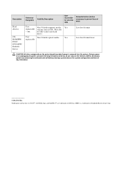
...lose data if power is a trademark of Dell Inc. Trademarks used in GB. SMSC is removed from the system. Description
Hard drive(s)
CDROM/RW/ DVD/ DVD+RW/ Diskette Drives
Reference Designator... text: Dell™, the DELL logo, and OptiPlex™ are trademarks of Standard Microsystems Corp. Primary power loss (unplugging the power cord and removing the battery) destroys all user data on the ...
Similar Questions

How To Remove Hdd From Dell Optiplex 9010 All In One
(Posted by Parkyk 9 years ago)

Where Are The Usb 2.0 Ports On My Dell Optiplex 9010
(Posted by cbjgmca 9 years ago)

Dell Optiplex 9010 All In One - How To Remove The Back Cover
(Posted by jo2gakaloia 9 years ago)
How To Factory Restore A Dell Optiplex 9010
(Posted by wizarBullet 10 years ago)
