Dell OptiPlex 390 Support Question
Dell OptiPlex 390 Support Question
Find answers below for this question about Dell OptiPlex 390.Need a Dell OptiPlex 390 manual? We have 3 online manuals for this item!
Question posted by hio0to on October 30th, 2013
How Do I Connect Power Switch Cable To Optiplex 390 Motherboard
The person who posted this question about this Dell product did not include a detailed explanation. Please use the "Request More Information" button to the right if more details would help you to answer this question.
Current Answers
Related Dell OptiPlex 390 Manual Pages
User Manual - Page 1
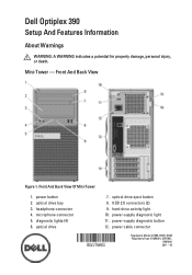
... light 10. power cable connector
Regulatory Model :D12M, D07D, D04S Regulatory Type :D12M001, D07D001,
D04S001 2011 - 05 Front And Back View
Figure 1. optical drive eject button 8. USB 2.0 connectors (2) 9. power-supply diagnostic light 11. Front And Back View Of Mini-Tower
1. optical drive bay 3. optical drive
7.
diagnostic lights (4) 6. Mini-Tower - Dell Optiplex 390
Setup And...
User Manual - Page 6
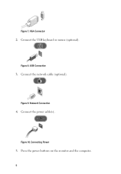
Network Connection
4.
USB Connection
3. Figure 9. Figure 8.
Connect the power cable(s). Figure 10. Connect the network cable (optional).
Connecting Power
5. Connect the USB keyboard or mouse (optional). Figure 7. VGA Connector
2. Press the power buttons on the monitor and the computer. 6
Technical Guide - Page 3
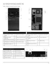
DELL™ OPTIPLEX™ 390 TECHNICAL GUIDEBOOK -FINAL
MINI TOWER COMPUTER (MT) VIEW
1
6
10
7
11
15
2
12
16
8 3
4
9
5
13
14
FRONT VIEW
BACK VIEW
1 Power Button, Power Light
6 Optical Drive (optional)
2 Optical Drive Bay (optional)
7 Optical Drive Eject Button
3 Microphone Connector 8 USB 2.0 Connectors (2)
4 Headphone Connector 9 Drive Activity Light
10 Power Supply ...
Technical Guide - Page 4
DELL™ OPTIPLEX™ 390 TECHNICAL GUIDEBOOK -FINAL
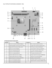
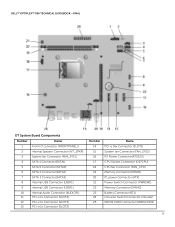
MT System Board Components
Number
Name
1
Front IO connector ...Connector (FAN_SYS2) P2 Power Connector(ATX12V) CPU Socket Connector (U27CPU) CPU fan Connector (FAN_CPU) Memory Connector(DIMM1) P1 power Connector (ATX) Power Switch Connector (PWRSW1) Memory Connector(DIMM2) Battery Connector (BT1) Intrusion Switch Connector (Intruder) KB/...
Technical Guide - Page 5
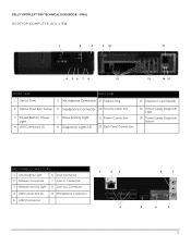
DELL™ OPTIPLEX™ 390 TECHNICAL GUIDEBOOK -FINAL DESKTOP COMPUTER (DT) VIEW
1
2
3
9 10
11
4 56 7 8
12
13
14 15
FRONT VIEW 1 Optical Drive
BACK VIEW 5 Microphone Connector 9 Padlock Ring
13 Expansion Card Slots(4)
2 Optical Drive Eject Button 6 Headphone Connector 10 Security Cable Slot
3 Power Button, Power Light
4 USB Connectors (2)
7 Drive Activity Light 8 Diagnostic ...
Technical Guide - Page 6
DELL™ OPTIPLEX™ 390 TECHNICAL GUIDEBOOK -FINAL
DT System Board Components
Number
Name
1
Front IO connector ...Connector (FAN_SYS2) P2 Power Connector(ATX12V) CPU Socket Connector (U27CPU) CPU fan Connector (FAN_CPU) Memory Connector(DIMM1) P1 power Connector (ATX) Power Switch Connector (PWRSW1) Memory Connector(DIMM2) Battery Connector (BT1) Intrusion Switch Connector (Intruder) KB/...
Technical Guide - Page 7
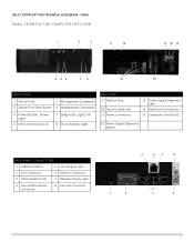
DELL™ OPTIPLEX™ 390 TECHNICAL GUIDEBOOK -FINAL SMALL FORM FACTOR COMPUTER (SFF) VIEW
1
2
3
9
10
11 12 13
4 56
7 8
14
15
FRONT VIEW
1 Optical Drive
5 Microphone Connector
2 Optical Drive Eject Button 6 Headphone Connector
3 Power Button, Power Light
4 USB 2.0 Connectors (2)
7 Diagnostic Lights (4) 8 Drive Activity Light
BACK VIEW 9 Padlock Ring
10 Security Cable Slot 11...
Technical Guide - Page 15
.... U.S. Technician will be provided by third-party.
For more details on Dell Service Plans please to go to Dell. DELL™ OPTIPLEX™ 390 TECHNICAL GUIDEBOOK -FINAL
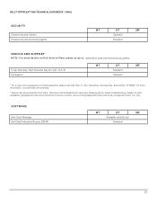
SECURITY Chassis Intrusion Switch Chassis lock slot and loop support
MT
DT
SFF
Optional
Standard
SERVICE AND SUPPORT
NOTE: For more information, visit www.dell.com...
Technical Guide - Page 18
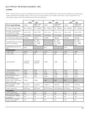
... auxiliary output -12.0v output Max total power Max combined +3.3v / +5.0v power Max combined 12.0v power (note: only if more efficient Active Power Factor Correction (APFC) power supply.
If you have questions, please contact the manufacture to confirm the output type. DELL™ OPTIPLEX™ 390 TECHNICAL GUIDEBOOK -FINAL POWER
NOTE: These form factors utilize a more...
Technical Guide - Page 20
...; OPTIPLEX™ 390 TECHNICAL GUIDEBOOK -FINAL
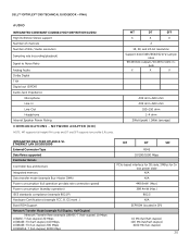
AUDIO
INTEGRATED CONEXANT CX20641 HIGH DEFINITION AUDIO High Definition Stereo support Number of channels Number of Bits / Audio resolution
Sampling rate (recording/playback)
Signal to Noise Ratio Analog Audio Dolby Digital THX Digital out (S/PDIF) Audio Jack Impedance
Microphone Line-In Line-Out Headphone Internal Speaker Power...
Technical Guide - Page 21
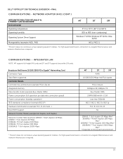
... memory Data transfer mode (example Bus-Master DMA) Power consumption (full operation per data rate connection speed) Power consumption (standby operation) IEEE standards compliance (example 802...(LP) cards.
DELL™ OPTIPLEX™ 390 TECHNICAL GUIDEBOOK -FINAL COMMUNICATIONS - COMMUNICATIONS - For high speed transmission, connection to a Gigabit Ethernet server and network infrastructure...
Technical Guide - Page 24
DELL™ OPTIPLEX™ 390 TECHNICAL GUIDEBOOK -FINAL
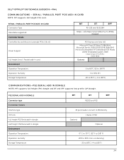
COMMUNICATIONS - PS2/SERIAL ADD IN DONGLE Connector type ...Support
Full height Serial / Parallel add-in dongle Environment Operation Temperature Operation Humidity Storage Temperature
MT
DT
SFF
RS232 and PS2
24 pins header connect to MB directly
Optional
1 Serial, 2 PS2 Optional
0° C to 70° C (32° F to 158° ...
Owners Manual - Page 4
... Sink And Processor 30
11 Coin-Cell Battery 31
Removing the Coin-Cell Battery 31 Installing The Coin-Cell Battery 32
12 Power Switch Cable 33
Removing the Power-Switch Cable 33 Installing The Power Switch Cable 34
13 System Fan 35
Removing the System Fan 35 Installing The System Fan 36
14 Input/Output Panel 37
Removing The...
Owners Manual - Page 9
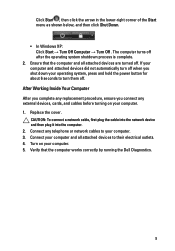
...running the Dell Diagnostics.
9 Connect your computer and all attached ...ensure you connect any telephone or network cables to turn off when you shut down your computer. 1. Connect any external devices, cards, and cables before turning... devices did not automatically turn them off.
CAUTION: To connect a network cable, first plug the cable into the network device and then plug it into the...
Owners Manual - Page 18
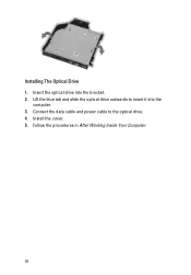
Install the cover. 5. Installing The Optical Drive 1. Follow the procedures in After Working Inside Your Computer.
18 Connect the data cable and power cable to insert it into the bracket. 2. Lift the blue tab and slide the optical drive outwards to the optical drive. 4. Insert the optical drive into the
computer. 3.
Owners Manual - Page 24

Install the cover. 4. Follow the procedures in After Working Inside Your Computer.
24 Installing The Intrusion Switch 1. Connect the intrusion-switch cable to
secure it. 2. Insert the intrusion switch into the chassis rear and slide it outward to the system board. 3.
Owners Manual - Page 33
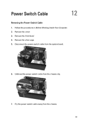
Remove the cover. 3. Disconnect the power-switch cable from the chassis. 33 Pry the power-switch cable away from the system board.
6. Unthread the power-switch cable from the chassis clip.
7. Remove the front bezel. 4. Follow the procedures in Before Working Inside Your Computer. 2. Remove the drive cage. 5. Power Switch Cable
12
Removing the Power-Switch Cable
1.
Owners Manual - Page 34
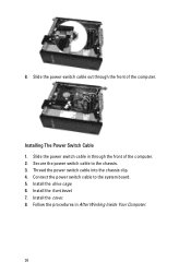
...the computer. Connect the power switch cable to the chassis. 3. Follow the procedures in through the front of the computer. 2. Slide the power switch cable in After Working Inside Your Computer.
34 Install the front bezel. 7. 8.
Install the drive cage. 6. Install the cover. 8. Secure the power switch cable to the system board. 5. Thread the power switch cable into the chassis...
Owners Manual - Page 47
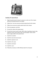
... 1. Install the front bezel. 12. Tighten the screws securing the system board to the system board. 7. Install the cover. 13. Install the expansion card. 10. Connect the intrusion switch cable, SATA cables, Input/Output board cable,
system fan cable, power switch cable, internal speaker cable, and the power supply cables to the chassis. 4. Install the drive cage. 11.
Owners Manual - Page 51
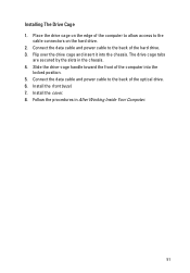
... the computer to allow access to the back of the optical drive. 6. Follow the procedures in the chassis. 4. Installing The Drive Cage 1. Connect the data cable and power cable to the
cable connectors on the edge of the computer into the chassis. Install the cover. 8. The drive cage tabs
are secured by the slots in...
Similar Questions


Why My Cpu Dell Optiplex 790 Power Switch Light Is Blinking
what cause this problem
what cause this problem
(Posted by kghoorun 11 years ago)