

User Guide
Page 3
... configure the Switch. • Supporting Disk Refer to the included CD for support documents. • ZyXEL Web Site Please refer to configure the GS-4024 or GS-4012F using the web configurator or via commands. E-mail: techwriters@zyxel.com.tw GS-4012F/4024 User's Guide 3 You should have at least a basic knowledge of individual screens and supplementary information. It...
... configure the Switch. • Supporting Disk Refer to the included CD for support documents. • ZyXEL Web Site Please refer to configure the GS-4024 or GS-4012F using the web configurator or via commands. E-mail: techwriters@zyxel.com.tw GS-4012F/4024 User's Guide 3 You should have at least a basic knowledge of individual screens and supplementary information. It...

User Guide
Page 4
... or your keyboard. • "Enter" means for you to use one or more characters and then press the [ENTER] key. Syntax Conventions • The GS-4024 and GS-4012F models may be referred to as the "Switch", the "device", the "system" or the "product" in the navigation panel, then the Log sub menu and... Setting means you to type one of the predefined choices. • A right angle bracket ( > ) within a screen name denotes a mouse click. " Notes tell you other words". 4 GS-4012F/4024 User's Guide
... or your keyboard. • "Enter" means for you to use one or more characters and then press the [ENTER] key. Syntax Conventions • The GS-4024 and GS-4012F models may be referred to as the "Switch", the "device", the "system" or the "product" in the navigation panel, then the Log sub menu and... Setting means you to type one of the predefined choices. • A right angle bracket ( > ) within a screen name denotes a mouse click. " Notes tell you other words". 4 GS-4012F/4024 User's Guide

User Guide
Page 5
The Switch icon is not an exact representation of your device. Document Conventions Icons Used in Figures Figures in this User's Guide may use the following generic icons. Switch Computer Notebook computer Server DSLAM Firewall Telephone Switch Router GS-4012F/4024 User's Guide 5
The Switch icon is not an exact representation of your device. Document Conventions Icons Used in Figures Figures in this User's Guide may use the following generic icons. Switch Computer Notebook computer Server DSLAM Firewall Telephone Switch Router GS-4012F/4024 User's Guide 5

User Guide
Page 6
... can expose you to dangerous high voltage points or other risks. ONLY qualified service personnel should not exceed 7mm. There is recyclable. Connect it properly. 6 GS-4012F/4024 User's Guide Dispose of electric shock from this device before servicing or disassembling. • Use ONLY an appropriate power adaptor or cord for example, 110V...
... can expose you to dangerous high voltage points or other risks. ONLY qualified service personnel should not exceed 7mm. There is recyclable. Connect it properly. 6 GS-4012F/4024 User's Guide Dispose of electric shock from this device before servicing or disassembling. • Use ONLY an appropriate power adaptor or cord for example, 110V...

User Guide
Page 7
Safety Warnings GS-4012F/4024 User's Guide 7
Safety Warnings GS-4012F/4024 User's Guide 7

User Guide
Page 8
Safety Warnings 8 GS-4012F/4024 User's Guide
Safety Warnings 8 GS-4012F/4024 User's Guide

User Guide
Page 9
... ...171 Authentication & Accounting ...185 IP Source Guard ...199 Loop Guard ...219 IP Application ...223 Static Route ...225 RIP ...227 OSPF ...229 IGMP ...241 DVMRP ...245 GS-4012F/4024 User's Guide 9
... ...171 Authentication & Accounting ...185 IP Source Guard ...199 Loop Guard ...219 IP Application ...223 Static Route ...225 RIP ...227 OSPF ...229 IGMP ...241 DVMRP ...245 GS-4012F/4024 User's Guide 9

User Guide
Page 10
... ...395 IEEE 802.1Q Tagged VLAN Commands 403 Multicast VLAN Registration Commands 411 Routing Domain Command Examples 413 Troubleshooting ...415 Appendices and Index ...423 10 GS-4012F/4024 User's Guide
... ...395 IEEE 802.1Q Tagged VLAN Commands 403 Multicast VLAN Registration Commands 411 Routing Domain Command Examples 413 Troubleshooting ...415 Appendices and Index ...423 10 GS-4012F/4024 User's Guide

User Guide
Page 25
... ...41 Figure 6 Attaching the Mounting Brackets 43 Figure 7 Mounting the Switch on a Rack 43 Figure 8 Front Panel: GS-4024 ...45 Figure 9 Front Panel: GS-4012F ...45 Figure 10 Transceiver Installation Example 47 Figure 11 Installed Transceiver ...48 Figure 12 Opening the Transceiver's Latch Example 48 Figure... 13 Transceiver Removal Example 48 Figure 14 Rear Panel: GS-4012F ...48 Figure 15 Rear Panel: GS-4024 ...49 Figure 16 Rear Panel: GS-4012F (DC Model 49 Figure 17 Rear Panel: GS-4024 (DC Model 49 Figure 18 Terminal Block Pairs ...50 Figure 19 Web Configurator...
... ...41 Figure 6 Attaching the Mounting Brackets 43 Figure 7 Mounting the Switch on a Rack 43 Figure 8 Front Panel: GS-4024 ...45 Figure 9 Front Panel: GS-4012F ...45 Figure 10 Transceiver Installation Example 47 Figure 11 Installed Transceiver ...48 Figure 12 Opening the Transceiver's Latch Example 48 Figure... 13 Transceiver Removal Example 48 Figure 14 Rear Panel: GS-4012F ...48 Figure 15 Rear Panel: GS-4024 ...49 Figure 16 Rear Panel: GS-4012F (DC Model 49 Figure 17 Rear Panel: GS-4024 (DC Model 49 Figure 18 Terminal Block Pairs ...50 Figure 19 Web Configurator...

User Guide
Page 37
..., the Switch can also be used standalone for a group of heavy traffic users. GS-4012F/4024 User's Guide 37 A dual personality interface includes one Gigabit port and one port active at a time. The GS-4012F AC model requires 100~240VAC, 1.6A power. With its built-in web configurator, ...Switch. In this example, all computers can share high-speed applications on the console port, or third-party SNMP management. The GS-4024 is easy. There are two GS-4012F models. See Appendix A on page 425 for a full list of software features available on the Switch. 1.1.1 Backbone Application ...
..., the Switch can also be used standalone for a group of heavy traffic users. GS-4012F/4024 User's Guide 37 A dual personality interface includes one Gigabit port and one port active at a time. The GS-4012F AC model requires 100~240VAC, 1.6A power. With its built-in web configurator, ...Switch. In this example, all computers can share high-speed applications on the console port, or third-party SNMP management. The GS-4024 is easy. There are two GS-4012F models. See Appendix A on page 425 for a full list of software features available on the Switch. 1.1.1 Backbone Application ...

User Guide
Page 45
... hardware connections. 3.1 Front Panel Connection The figure below shows the front panel of the Switch. GS-4012F/4024 User's Guide 45 Figure 8 Front Panel: GS-4024 Figure 9 Front Panel: GS-4012F The following table describes the port labels on the front panel. GS-4024 Model 20 100/1000 Mbps RJ-45 Gigabit Ethernet Ports Connect these ports to a computer...
... hardware connections. 3.1 Front Panel Connection The figure below shows the front panel of the Switch. GS-4012F/4024 User's Guide 45 Figure 8 Front Panel: GS-4024 Figure 9 Front Panel: GS-4012F The following table describes the port labels on the front panel. GS-4024 Model 20 100/1000 Mbps RJ-45 Gigabit Ethernet Ports Connect these ports to a computer...

User Guide
Page 49
...only for the AC models of the fans. Connect the other end of your Switch. Figure 15 Rear Panel: GS-4024 Chapter 3 Hardware Overview Figure 16 Rear Panel: GS-4012F (DC Model) Figure 17 Rear Panel: GS-4024 (DC Model) 3.3 Power Connections Overview Use the following procedures to connect the Switch to a power source after ... on page 425, and make sure you are using an appropriate power source. Make sure that no objects obstruct the airflow of the Switch. GS-4012F/4024 User's Guide 49 " Check the power supply requirements in the OFF position until you have installed it.
...only for the AC models of the fans. Connect the other end of your Switch. Figure 15 Rear Panel: GS-4024 Chapter 3 Hardware Overview Figure 16 Rear Panel: GS-4012F (DC Model) Figure 17 Rear Panel: GS-4024 (DC Model) 3.3 Power Connections Overview Use the following procedures to connect the Switch to a power source after ... on page 425, and make sure you are using an appropriate power source. Make sure that no objects obstruct the airflow of the Switch. GS-4012F/4024 User's Guide 49 " Check the power supply requirements in the OFF position until you have installed it.

User Guide
Page 51
... supply is connected and active. Blinking The port is in full duplex mode. FDX Amber On The port is sending or receiving data. GS-4012F/4024 User's Guide 51 Once the Switch receives power from the backup power supply. Table 2 LEDs LED COLOR STATUS DESCRIPTION BPS Green Blinking The... is down . Off The link to a 10 Mbps Ethernet network is rebooting and performing self-diagnostic tests. Off The system is up . GS-4024 Model Gigabit Ethernet Ports LNK/ACT Green On The port has a successful 10/1000 Mbps connection. Amber On The port has a successful 100 ...
... supply is connected and active. Blinking The port is in full duplex mode. FDX Amber On The port is sending or receiving data. GS-4012F/4024 User's Guide 51 Once the Switch receives power from the backup power supply. Table 2 LEDs LED COLOR STATUS DESCRIPTION BPS Green Blinking The... is down . Off The link to a 10 Mbps Ethernet network is rebooting and performing self-diagnostic tests. Off The system is up . GS-4024 Model Gigabit Ethernet Ports LNK/ACT Green On The port has a successful 10/1000 Mbps connection. Amber On The port has a successful 100 ...

User Guide
Page 63
... online help description of that screen. You have to log in a screen to exit the web configurator. Erasing OK GS-4024> atgo The Switch is recommended after you finish a management session for security reasons. This is now reinitialized with your ...log out. Click the Help link from a web configurator screen to enter debug mode within 3 seconds Enter Debug Mode GS-4024> atlc Starting XMODEM upload (CRC mode).... FLASH: Intel 64M ZyNOS Version: V3.80(TS.0)b4 | 03/31/...:36:17 RAM:Size = 64 Mbytes DRAM POST: Testing: 65536K OK DRAM Test SUCCESS ! GS-4012F/4024 User's Guide 63
... online help description of that screen. You have to log in a screen to exit the web configurator. Erasing OK GS-4024> atgo The Switch is recommended after you finish a management session for security reasons. This is now reinitialized with your ...log out. Click the Help link from a web configurator screen to enter debug mode within 3 seconds Enter Debug Mode GS-4024> atlc Starting XMODEM upload (CRC mode).... FLASH: Intel 64M ZyNOS Version: V3.80(TS.0)b4 | 03/31/...:36:17 RAM:Size = 64 Mbytes DRAM POST: Testing: 65536K OK DRAM Test SUCCESS ! GS-4012F/4024 User's Guide 63

User Guide
Page 287
... is sent when the fan speed returns to the normal operating range. GS-4012F: 1.3.6.1.4.1.890.1.5.8.20.37.2.2 GS-4024: 1.3.6.1.4.1.890.1.5.8.13.37.2.2 This trap is a standard MIB OID. GS-4012F: 1.3.6.1.4.1.890.1.5.8.20.37.2.1 GS-4024: 1.3.6.1.4.1.890.1.5.8.13.37.2.1 This trap is sent when the Switch restarts. GS-4012F/4024 User's Guide 287 SNMP managers can be further enhanced by category. The...
... is sent when the fan speed returns to the normal operating range. GS-4012F: 1.3.6.1.4.1.890.1.5.8.20.37.2.2 GS-4024: 1.3.6.1.4.1.890.1.5.8.13.37.2.2 This trap is a standard MIB OID. GS-4012F: 1.3.6.1.4.1.890.1.5.8.20.37.2.1 GS-4024: 1.3.6.1.4.1.890.1.5.8.13.37.2.1 This trap is sent when the Switch restarts. GS-4012F/4024 User's Guide 287 SNMP managers can be further enhanced by category. The...

User Guide
Page 288
... the time and date from a time server. GS-4012F: 1.3.6.1.4.1.890.1.5.8.20.37.2.1 GS-4024: 1.3.6.1.4.1.890.1.5.8.13.37.2.1 This trap is sent when loopguard shuts down a port. 288 GS-4012F/4024 User's Guide GS-4012F: 1.3.6.1.4.1.890.1.5.8.20.37.2.1 GS-4024: 1.3.6.1.4.1.890.1.5.8.13.37.2.1 This trap is sent when the Switch automatically resets. GS-4012F: 1.3.6.1.4.1.890.1.5.8.20.37.2.2 GS-4024: 1.3.6.1.4.1.890.1.5.8.13.37.2.2 This trap is sent...
... the time and date from a time server. GS-4012F: 1.3.6.1.4.1.890.1.5.8.20.37.2.1 GS-4024: 1.3.6.1.4.1.890.1.5.8.13.37.2.1 This trap is sent when loopguard shuts down a port. 288 GS-4012F/4024 User's Guide GS-4012F: 1.3.6.1.4.1.890.1.5.8.20.37.2.1 GS-4024: 1.3.6.1.4.1.890.1.5.8.13.37.2.1 This trap is sent when the Switch automatically resets. GS-4012F: 1.3.6.1.4.1.890.1.5.8.20.37.2.2 GS-4024: 1.3.6.1.4.1.890.1.5.8.13.37.2.2 This trap is sent...

User Guide
Page 289
...OPTION linkup OBJECT LABEL linkUp OBJECT ID 1.3.6.1.6.3.1.1.5.4 LinkDownEventClear linkdown linkDown GS-4012F: 1.3.6.1.4.1.890.1.5.8.20.37.2.2 GS-4024: 1.3.6.1.4.1.890.1.5.8.13.37.2.2 1.3.6.1.6.3.1.1.5.3 LinkDownEventOn GS-4012F: 1.3.6.1.4.1.890.1.5.8.20.37.2.1 GS-4024: 1.3.6.1.4.1.890.1.5.8.13.37.2.1 autonegotiation AutonegotiationFailedEventO n GS-4012F: 1.3.6.1.4.1.890.1.5.8.20.37.2.1 GS-4024: 1.3.6.1.4.1.890.1.5.8.13.37.2.1 AutonegotiationFailedEventCl GS-4012F: ear 1.3.6.1.4.1.890.1.5.8.20.37.2.2 GS-4024: 1.3.6.1.4.1.890.1.5.8.13.37.2.2 DESCRIPTION This trap is sent when...
...OPTION linkup OBJECT LABEL linkUp OBJECT ID 1.3.6.1.6.3.1.1.5.4 LinkDownEventClear linkdown linkDown GS-4012F: 1.3.6.1.4.1.890.1.5.8.20.37.2.2 GS-4024: 1.3.6.1.4.1.890.1.5.8.13.37.2.2 1.3.6.1.6.3.1.1.5.3 LinkDownEventOn GS-4012F: 1.3.6.1.4.1.890.1.5.8.20.37.2.1 GS-4024: 1.3.6.1.4.1.890.1.5.8.13.37.2.1 autonegotiation AutonegotiationFailedEventO n GS-4012F: 1.3.6.1.4.1.890.1.5.8.20.37.2.1 GS-4024: 1.3.6.1.4.1.890.1.5.8.13.37.2.1 AutonegotiationFailedEventCl GS-4012F: ear 1.3.6.1.4.1.890.1.5.8.20.37.2.2 GS-4024: 1.3.6.1.4.1.890.1.5.8.13.37.2.2 DESCRIPTION This trap is sent when...

User Guide
Page 290
... traceRouteTestCompleted OBJECT ID 1.3.6.1.2.1.80.0.1 1.3.6.1.2.1.80.0.2 1.3.6.1.2.1.80.0.3 1.3.6.1.2.1.81.0.2 1.3.6.1.2.1.81.0.3 DESCRIPTION This trap is sent when the RADIUS accounting server can be reached. RADIUSAccountingNotReach ableEventClear GS-4012F: 1.3.6.1.4.1.890.1.5.8.20.37.2.2 GS-4024: 1.3.6.1.4.1.890.1.5.8.13.37.2.2 This trap is sent when a single ping probe fails. This trap is sent when a traceroute test is sent when a traceroute test...
... traceRouteTestCompleted OBJECT ID 1.3.6.1.2.1.80.0.1 1.3.6.1.2.1.80.0.2 1.3.6.1.2.1.80.0.3 1.3.6.1.2.1.81.0.2 1.3.6.1.2.1.81.0.3 DESCRIPTION This trap is sent when the RADIUS accounting server can be reached. RADIUSAccountingNotReach ableEventClear GS-4012F: 1.3.6.1.4.1.890.1.5.8.20.37.2.2 GS-4024: 1.3.6.1.4.1.890.1.5.8.13.37.2.2 This trap is sent when a single ping probe fails. This trap is sent when a traceroute test is sent when a traceroute test...
User Guide
Page 291
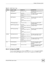
... trap is sent when the MSTP root switch changes. GS-4012F: 1.3.6.1.4.1.890.1.5.8.20.107.7 0.2 GS-4024: 1.3.6.1.4.1.890.1.5.8.13.107.7 0.2 This trap is sent when the STP topology changes. GS-4012F: 1.3.6.1.4.1.890.1.5.8.20.37.2.2 GS-4024: 1.3.6.1.4.1.890.1.5.8.13.37.2.2 This trap is sent when ...the RMON "rising" threshold. 1.3.6.1.2.1.16.0.2 This trap is sent when the MRSTP root switch changes. GS-4012F/4024 User's Guide 291 GS-4012F: 1.3.6.1.4.1.890.1.5.8.20.43.2.1 GS-4024: 1.3.6.1.4.1.890.1.5.8.13.43.2.1 This trap is sent when the variable falls below the RMON "falling" ...
... trap is sent when the MSTP root switch changes. GS-4012F: 1.3.6.1.4.1.890.1.5.8.20.107.7 0.2 GS-4024: 1.3.6.1.4.1.890.1.5.8.13.107.7 0.2 This trap is sent when the STP topology changes. GS-4012F: 1.3.6.1.4.1.890.1.5.8.20.37.2.2 GS-4024: 1.3.6.1.4.1.890.1.5.8.13.37.2.2 This trap is sent when ...the RMON "rising" threshold. 1.3.6.1.2.1.16.0.2 This trap is sent when the MRSTP root switch changes. GS-4012F/4024 User's Guide 291 GS-4012F: 1.3.6.1.4.1.890.1.5.8.20.43.2.1 GS-4024: 1.3.6.1.4.1.890.1.5.8.13.43.2.1 This trap is sent when the variable falls below the RMON "falling" ...
User Guide
Page 425
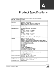
...Dimensions Standard 19" rack mountable GS-4012F: 438 mm (W) x 225 mm (D) x 44.45 mm (H) GS-4024: 438 mm (W) x 300 mm (D) x 44.45 mm (H) Weight GS-4012F: 3.1 Kg GS-4024: 4.2 Kg Power Specification One Backup Power Supply (BPS) connector GS-4012F AC: 100-240 VAC 50/60 Hz, 1.5 A Max. GS-4024 AC: 100-240 VAC ...Max. Interfaces LEDs Operating Environment Storage Environment Ground Wire Gauge Note: There is no tolerance for the DC input voltage GS-4012F: 8 mini-GBIC (SFP) slots GS-4024: 20 10/100/1000 Base-Tx ports All Models: 4 GbE Dual Personality interfaces (Each interface has one 1000Base-T...
...Dimensions Standard 19" rack mountable GS-4012F: 438 mm (W) x 225 mm (D) x 44.45 mm (H) GS-4024: 438 mm (W) x 300 mm (D) x 44.45 mm (H) Weight GS-4012F: 3.1 Kg GS-4024: 4.2 Kg Power Specification One Backup Power Supply (BPS) connector GS-4012F AC: 100-240 VAC 50/60 Hz, 1.5 A Max. GS-4024 AC: 100-240 VAC ...Max. Interfaces LEDs Operating Environment Storage Environment Ground Wire Gauge Note: There is no tolerance for the DC input voltage GS-4012F: 8 mini-GBIC (SFP) slots GS-4024: 20 10/100/1000 Base-Tx ports All Models: 4 GbE Dual Personality interfaces (Each interface has one 1000Base-T...
