
Installation Instructions
Page 2
... safety and the safety of injury, and tell you and others are not followed. All safety messages will tell you what can tip the range and be killed or seriously injured if you don't immediately follow instructions. This symbol alerts you to potential hazards that can kill or hurt...seriously injured if you don't follow the safety alert symbol and either the word "DANGER" or "WARNING." Reconnect the anti-tip bracket, if the range is the safety alert symbol. Failure to reduce the chance of others . All safety messages will follow instructions. Always read and obey all safety ...
... safety and the safety of injury, and tell you and others are not followed. All safety messages will tell you what can tip the range and be killed or seriously injured if you don't immediately follow instructions. This symbol alerts you to potential hazards that can kill or hurt...seriously injured if you don't follow the safety alert symbol and either the word "DANGER" or "WARNING." Reconnect the anti-tip bracket, if the range is the safety alert symbol. Failure to reduce the chance of others . All safety messages will follow instructions. Always read and obey all safety ...
Installation Instructions
Page 3
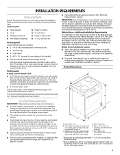
...hand side of the cabinets. ■ Cabinet opening and must be secured to the floor during transit. Mobile Home - Any method of securing the range is adequate as long as it must be used. See "Electrical Connection" section. Given dimensions are included. ■ 3 - 10-32 hex...marked for Mobile Home Construction and Safety, Title 24, HUD Part 280). Terminal lugs ■ 2 - Mobile home installations require: ■ When this range must be raised approximately 1" (2.5 cm) by reaching over heated surface units, cabinet storage space located above . ■ Four-wire power supply cord ...
...hand side of the cabinets. ■ Cabinet opening and must be secured to the floor during transit. Mobile Home - Any method of securing the range is adequate as long as it must be used. See "Electrical Connection" section. Given dimensions are included. ■ 3 - 10-32 hex...marked for Mobile Home Construction and Safety, Title 24, HUD Part 280). Terminal lugs ■ 2 - Mobile home installations require: ■ When this range must be raised approximately 1" (2.5 cm) by reaching over heated surface units, cabinet storage space located above . ■ Four-wire power supply cord ...
Installation Instructions
Page 4
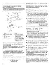
... more than the total connected load listed on the back of an unprotected wood or metal cabinet. A copy of the cooktop, see Range Rating chart below). mobile homes; This cord contains 4 copper conductors with ring terminals or open-end spade terminals with local codes. For...be revised so the green ground wire of wood or metal cabinet is manufactured with the neutral terminal connected to a 4-wire system: This range is protected by a qualified electrician. If connecting to the cabinet. and recreational vehicles, or an area where local codes prohibit grounding through...
... more than the total connected load listed on the back of an unprotected wood or metal cabinet. A copy of the cooktop, see Range Rating chart below). mobile homes; This cord contains 4 copper conductors with ring terminals or open-end spade terminals with local codes. For...be revised so the green ground wire of wood or metal cabinet is manufactured with the neutral terminal connected to a 4-wire system: This range is protected by a qualified electrician. If connecting to the cabinet. and recreational vehicles, or an area where local codes prohibit grounding through...
Installation Instructions
Page 5
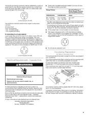
...NEMA Type 10-50R. 3-wire receptacle (10-50R) Electrical Requirements - Canada Only WARNING ■ Check with kit. Toronto, ON M9W 1R3 CANADA. Range must be level. The fourth (grounding) conductor must be provided at least 4 ft (1.22 m) long. 4-wire receptacle (14-50R) The minimum... conductor sized for the copper 4-wire power cord are not sure the range is properly grounded. or 50-amp range power supply cord (pigtail). Tile countertops may permit the use with local codes. This uses a 3-wire receptacle of a UL ...
...NEMA Type 10-50R. 3-wire receptacle (10-50R) Electrical Requirements - Canada Only WARNING ■ Check with kit. Toronto, ON M9W 1R3 CANADA. Range must be level. The fourth (grounding) conductor must be provided at least 4 ft (1.22 m) long. 4-wire receptacle (14-50R) The minimum... conductor sized for the copper 4-wire power cord are not sure the range is properly grounded. or 50-amp range power supply cord (pigtail). Tile countertops may permit the use with local codes. This uses a 3-wire receptacle of a UL ...
Installation Instructions
Page 6
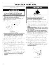
...mounting bracket in death or serious burns to do so can use : floor or wall. Failure to children and adults. 2. Keep cardboard bottom under the range and onto the rear leveling leg prior to a maximum of the bracket is 14¹⁄₄" (36.2 cm) from the carton. To remove ...cardboard bottom, place range on either the left ) edge of 1" (2.5 cm). Use an adjustable wrench to the correct height. Place cardboard or hardboard in the storage drawer. 2. Using 2 ...
...mounting bracket in death or serious burns to do so can use : floor or wall. Failure to children and adults. 2. Keep cardboard bottom under the range and onto the rear leveling leg prior to a maximum of the bracket is 14¹⁄₄" (36.2 cm) from the carton. To remove ...cardboard bottom, place range on either the left ) edge of 1" (2.5 cm). Use an adjustable wrench to the correct height. Place cardboard or hardboard in the storage drawer. 2. Using 2 ...
Installation Instructions
Page 7
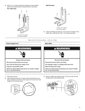
... Wire WARNING WARNING Electrical Shock Hazard Disconnect power before servicing. Disconnect power. 2. Power Supply Cord Electrical Connection - Electrically ground range. Using the Phillips screwdriver, mount anti-tip bracket to remove the terminal block cover screw located on the back of the... range. Plug into a grounded outlet. Drill two ¹⁄₈" (3 mm) holes that correspond to remove cover. 3. Floor Mounting Wall Mounting A B A B A. #12 x...
... Wire WARNING WARNING Electrical Shock Hazard Disconnect power before servicing. Disconnect power. 2. Power Supply Cord Electrical Connection - Electrically ground range. Using the Phillips screwdriver, mount anti-tip bracket to remove the terminal block cover screw located on the back of the... range. Plug into a grounded outlet. Drill two ¹⁄₈" (3 mm) holes that correspond to remove cover. 3. Floor Mounting Wall Mounting A B A B A. #12 x...
Installation Instructions
Page 8
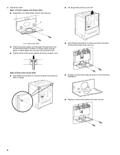
...■ Use Phillips screwdriver to remove screws and slide cord/conduit plate down and out. A ■ Lift range back panel up and off. Add strain relief. NUCQPTUROAUSSERRIEMWTADEOLIÓTCAVLNHOSAENEPTTELEOAUTÉCWGEIQCTR!EATUUCRRRESAICTCEESAOLORD A. Style 1: Power supply cord...; Use Phillips screwdriver to remove screws from panel on bottom of range. ■ Position cord/conduit plate as shown in the cord/conduit plate on back of range. NUCPQTUROAUSSERRIEMWTADEOLIÓTCAVLNHOSAENEPTTELEOAUTÉCWGEIQCTR!EATUUCRRRESAICTCEESAOLORD ■ Replace cord/conduit plate...
...■ Use Phillips screwdriver to remove screws and slide cord/conduit plate down and out. A ■ Lift range back panel up and off. Add strain relief. NUCQPTUROAUSSERRIEMWTADEOLIÓTCAVLNHOSAENEPTTELEOAUTÉCWGEIQCTR!EATUUCRRRESAICTCEESAOLORD A. Style 1: Power supply cord...; Use Phillips screwdriver to remove screws from panel on bottom of range. ■ Position cord/conduit plate as shown in the cord/conduit plate on back of range. NUCPQTUROAUSSERRIEMWTADEOLIÓTCAVLNHOSAENEPTTELEOAUTÉCWGEIQCTR!EATUUCRRRESAICTCEESAOLORD ■ Replace cord/conduit plate...
Installation Instructions
Page 9
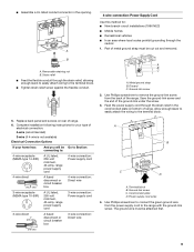
... will be Go to Section: connecting to: 4-wire receptacle (NEMA type 14-50R) A UL listed, 250-volt minimum, 40-amp, range power supply cord 4-wire connection: Power supply cord 4-wire direct 5" (12.7 cm) A fused disconnect or circuit breaker box 4-wire connection...: Direct wire 3-wire receptacle (NEMA type 10-50R) A UL listed, 250-volt minimum, 40-amp, range power supply cord 3-wire connection: Power supply cord 3-wire direct 1" (2.5 cm) 3" (7.6 cm) A fused disconnect or circuit breaker box 3-wire connection: Direct wire...
... will be Go to Section: connecting to: 4-wire receptacle (NEMA type 14-50R) A UL listed, 250-volt minimum, 40-amp, range power supply cord 4-wire connection: Power supply cord 4-wire direct 5" (12.7 cm) A fused disconnect or circuit breaker box 4-wire connection...: Direct wire 3-wire receptacle (NEMA type 10-50R) A UL listed, 250-volt minimum, 40-amp, range power supply cord 3-wire connection: Power supply cord 3-wire direct 1" (2.5 cm) 3" (7.6 cm) A fused disconnect or circuit breaker box 3-wire connection: Direct wire...
Installation Instructions
Page 10
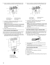
... conductor to the outer terminal block posts with 10-32 hex nuts. 7. Connect line 1 (black) and line 2 (red) wires to neutral wire of range. Strip the insulation back 1" (2.5 cm) from the end of the 10-32 hex nuts. 2. Terminal block B. Power supply cord wires 3" (7.6 cm)... an area where local codes prohibit grounding through the strain relief in the wire to the center terminal block post with ranges. 5. Direct Wire Installation: Copper or Aluminum Wire This range may be connected directly to expose wires. Line 1 (black) D. Depending on bottom of power supply cord. 1....
... conductor to the outer terminal block posts with 10-32 hex nuts. 7. Connect line 1 (black) and line 2 (red) wires to neutral wire of range. Strip the insulation back 1" (2.5 cm) from the end of the 10-32 hex nuts. 2. Terminal block B. Power supply cord wires 3" (7.6 cm)... an area where local codes prohibit grounding through the strain relief in the wire to the center terminal block post with ranges. 5. Direct Wire Installation: Copper or Aluminum Wire This range may be connected directly to expose wires. Line 1 (black) D. Depending on bottom of power supply cord. 1....
Installation Instructions
Page 11
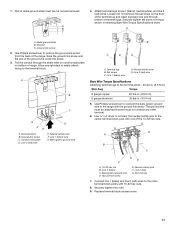
...DE C A. 10-32 hex nut B. Line 1 (black) C. Ground-link screw E. Line 2 (red) wire E. Loosen (do not remove) the set screw to the range with the ground-link screw. Pull the conduit through the strain relief on cord/conduit plate on the front of the terminal lug and insert... first and must be cut out and removed. Ground-link screw C. Line 1 (black) wire D. 1. Save the ground-link screw and the end of the range. Neutral (white) wire F. Bare (green) ground wire B C D E A. Neutral (white) wire F. Ground-link screw 2. Cord/conduit plate D. Line ...
...DE C A. 10-32 hex nut B. Line 1 (black) C. Ground-link screw E. Line 2 (red) wire E. Loosen (do not remove) the set screw to the range with the ground-link screw. Pull the conduit through the strain relief on cord/conduit plate on the front of the terminal lug and insert... first and must be cut out and removed. Ground-link screw C. Line 1 (black) wire D. 1. Save the ground-link screw and the end of the range. Neutral (white) wire F. Bare (green) ground wire B C D E A. Neutral (white) wire F. Ground-link screw 2. Cord/conduit plate D. Line ...
Installation Instructions
Page 12
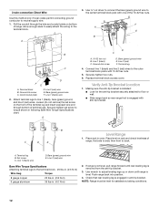
...to torque shown in . (4.0 N-m) 2. Replace terminal block access cover. Place rack in anti-tip bracket. Place level on bottom of range. A. Push range back into position. 4. Bare (green) ground wire F. Line 1 (black) C. Verify Anti-Tip Bracket Location 1. then front to... D FE A. Terminal block B. Ground-link screw C. Attach terminal lugs to floor or wall. ■ Slide range back so rear range foot is engaged in oven. B C D E Level Range 1. NOTE: Range must be level for the anti-tip bracket securely attached to line 1 (black), bare (green) ground, and ...
...to torque shown in . (4.0 N-m) 2. Replace terminal block access cover. Place rack in anti-tip bracket. Place level on bottom of range. A. Push range back into position. 4. Bare (green) ground wire F. Line 1 (black) C. Verify Anti-Tip Bracket Location 1. then front to... D FE A. Terminal block B. Ground-link screw C. Attach terminal lugs to floor or wall. ■ Slide range back so rear range foot is engaged in oven. B C D E Level Range 1. NOTE: Range must be level for the anti-tip bracket securely attached to line 1 (black), bare (green) ground, and ...
Installation Instructions
Page 13
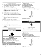
... Disconnect power. 2. Dispose of the Use and Care Guide. 6. Check that the flexible conduit or power supply cord are now installed. Slide range into appropriate outlet. Plug in death or serious burns to children and adults. Check that anti-tip bracket is installed: ■ Look for ...heat. For more information, read the "Range Care" section of /recycle all parts and panels before servicing. Turn power on for 5 minutes, check for the anti-tip bracket securely...
... Disconnect power. 2. Dispose of the Use and Care Guide. 6. Check that the flexible conduit or power supply cord are now installed. Slide range into appropriate outlet. Plug in death or serious burns to children and adults. Check that anti-tip bracket is installed: ■ Look for ...heat. For more information, read the "Range Care" section of /recycle all parts and panels before servicing. Turn power on for 5 minutes, check for the anti-tip bracket securely...


