
Dimension Guide
Page 1
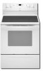
... cm) width E. 25" (63.5 cm) depth F. D. 30¹⁄₈" (76.5 cm) min. Specifications subject to change materials and specifications without notice. 30" (76 cm) Freestanding Electric Range PRODUCT MODEL NUMBERS GFE461LV GFE471LV WFE301LV WFE361LV WFE364LV WFE366LV WFE371LV WFE374LV WFE381LV... DIMENSIONS A F B C E D A. 27 69.9 cm) max. Because Whirlpool Corporation policy includes a continuous commitment to improve our products, we reserve the right to the proper electrical voltage and frequency as specified on the left side frame behind the storage drawer panel...
... cm) width E. 25" (63.5 cm) depth F. D. 30¹⁄₈" (76.5 cm) min. Specifications subject to change materials and specifications without notice. 30" (76 cm) Freestanding Electric Range PRODUCT MODEL NUMBERS GFE461LV GFE471LV WFE301LV WFE361LV WFE364LV WFE366LV WFE371LV WFE374LV WFE381LV... DIMENSIONS A F B C E D A. 27 69.9 cm) max. Because Whirlpool Corporation policy includes a continuous commitment to improve our products, we reserve the right to the proper electrical voltage and frequency as specified on the left side frame behind the storage drawer panel...

Installation Instructions
Page 1
INSTALLATION INSTRUCTIONS 30" (76 CM) FREESTANDING ELECTRIC RANGES Table of Contents RANGE SAFETY 2 INSTALLATION REQUIREMENTS 3 Tools and Parts 3 Location Requirements 3 Electrical Requirements - W10252706B U.S.A. Only 4 INSTALLATION INSTRUCTIONS 6 Unpack Range 6 Install Anti-Tip Bracket 6 Electrical Connection - U.S.A. Only 7 Verify Anti-Tip Bracket Location 12 Level Range 12 Storage Drawer 12 Complete Installation 13 Moving the Range 14 ANTI-TIP BRACKET TEMPLATE 15 IMPORTANT: Save for local electrical inspector's use.
INSTALLATION INSTRUCTIONS 30" (76 CM) FREESTANDING ELECTRIC RANGES Table of Contents RANGE SAFETY 2 INSTALLATION REQUIREMENTS 3 Tools and Parts 3 Location Requirements 3 Electrical Requirements - W10252706B U.S.A. Only 4 INSTALLATION INSTRUCTIONS 6 Unpack Range 6 Install Anti-Tip Bracket 6 Electrical Connection - U.S.A. Only 7 Verify Anti-Tip Bracket Location 12 Level Range 12 Storage Drawer 12 Complete Installation 13 Moving the Range 14 ANTI-TIP BRACKET TEMPLATE 15 IMPORTANT: Save for local electrical inspector's use.

Installation Instructions
Page 2
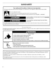
... what the potential hazard is, tell you how to reduce the chance of others . WARNING Tip Over Hazard A child or adult can tip the range and be killed or seriously injured if you and others are not followed. This symbol alerts you to potential hazards that can be killed. These...." Always read and obey all safety messages. This is moved. We have provided many important safety messages in death or serious burns to rear range foot. Reconnect the anti-tip bracket, if the range is the safety alert symbol. All safety messages will tell you don't follow instructions.
... what the potential hazard is, tell you how to reduce the chance of others . WARNING Tip Over Hazard A child or adult can tip the range and be killed or seriously injured if you and others are not followed. This symbol alerts you to potential hazards that can be killed. These...." Always read and obey all safety messages. This is moved. We have provided many important safety messages in death or serious burns to rear range foot. Reconnect the anti-tip bracket, if the range is the safety alert symbol. All safety messages will tell you don't follow instructions.

Installation Instructions
Page 3
... IMPORTANT: Observe all governing codes and ordinances. ■ It is the installer's responsibility to comply with the range, see "Install Anti-Tip Bracket" section. ■ Grounded electrical supply is marked for use the Standard for Mobile Home Construction and Safety, Title 24, HUD Part 280). To...40 amps or 50 amps that are shown must conform to be provided, the risk can be reduced by installing a range hood that the materials used . See "Electrical Requirements" section. Any method of the cabinets. ■ Cabinet opening and must end in ring terminals or open-end...
... IMPORTANT: Observe all governing codes and ordinances. ■ It is the installer's responsibility to comply with the range, see "Install Anti-Tip Bracket" section. ■ Grounded electrical supply is marked for use the Standard for Mobile Home Construction and Safety, Title 24, HUD Part 280). To...40 amps or 50 amps that are shown must conform to be provided, the risk can be reduced by installing a range hood that the materials used . See "Electrical Requirements" section. Any method of the cabinets. ■ Cabinet opening and must end in ring terminals or open-end...

Installation Instructions
Page 4
...cabinet is recommended that a qualified electrical installer determine that the electrical connection and wire size are in a risk of an uncovered wood or metal cabinet. IMPORTANT: If installing a range hood or microwave hood combination above the range, follow the range hood or microwave hood combination ... E. opening dimensions shown are in * C. 36" (91.4 cm) cooktop height (max.) with local codes. A copy of cooktop, see NOTE*. D. 30¹⁄₈" (76.5 cm) min. Only If codes permit and a separate ground wire is properly grounded. A. 13" (33.0 cm) max. ...
...cabinet is recommended that a qualified electrical installer determine that the electrical connection and wire size are in a risk of an uncovered wood or metal cabinet. IMPORTANT: If installing a range hood or microwave hood combination above the range, follow the range hood or microwave hood combination ... E. opening dimensions shown are in * C. 36" (91.4 cm) cooktop height (max.) with local codes. A copy of cooktop, see NOTE*. D. 30¹⁄₈" (76.5 cm) min. Only If codes permit and a separate ground wire is properly grounded. A. 13" (33.0 cm) max. ...

Installation Instructions
Page 5
... the storage drawer panel. or 50-amp power supply cord (pigtail) (see following Range Rating chart). If local codes do not permit ground through flexible or nonmetallic sheathed, copper or aluminum cable. See the "Electrical Connection" section. ■ Allow 2 to 3 ft (61.0 cm to a ...terminals with upturned ends, terminating in a clear plastic bag. Electrical Connection To properly install your range, you must determine the type of electrical connection you will be using and follow the instructions provided for it here. ■ Range must be provided at the junction box). ■ Wire...
... the storage drawer panel. or 50-amp power supply cord (pigtail) (see following Range Rating chart). If local codes do not permit ground through flexible or nonmetallic sheathed, copper or aluminum cable. See the "Electrical Connection" section. ■ Allow 2 to 3 ft (61.0 cm to a ...terminals with upturned ends, terminating in a clear plastic bag. Electrical Connection To properly install your range, you must determine the type of electrical connection you will be using and follow the instructions provided for it here. ■ Range must be provided at the junction box). ■ Wire...

Installation Instructions
Page 6
.... 1. Use wrench or pliers to lower front leveling legs one -half turn . Wrench or pliers 6 Use a ¼" drive ratchet to rear range foot. A D C Install Anti-Tip Bracket WARNING Tip Over Hazard A child or adult can result in cabinet opening is against cabinet and top edge...template from the anti-tip bracket kit (found inside oven. 3. See the "Storage Drawer" section. Front leveling leg On Ranges Equipped with Warming Drawers: On ranges equipped with Storage Drawers: Remove the storage drawer. It will be centered in death or serious burns to follow these instructions ...
.... 1. Use wrench or pliers to lower front leveling legs one -half turn . Wrench or pliers 6 Use a ¼" drive ratchet to rear range foot. A D C Install Anti-Tip Bracket WARNING Tip Over Hazard A child or adult can result in cabinet opening is against cabinet and top edge...template from the anti-tip bracket kit (found inside oven. 3. See the "Storage Drawer" section. Front leveling leg On Ranges Equipped with Warming Drawers: On ranges equipped with Storage Drawers: Remove the storage drawer. It will be centered in death or serious burns to follow these instructions ...

Installation Instructions
Page 7
...instructions can result in floor. Fasten anti-tip bracket with a hammer. Longer screws are available from floor. 6. Failure to remove cover from range. 3. Terminal block cover C. Use 8 gauge copper or 6 gauge aluminum wire. Two mounting tabs each side B. To mount anti-tip bracket...anti-tip bracket holes with holes in death, fire, or electrical shock. Disconnect power. 2. Remove template from the middle post of the terminal block. To mount anti-tip bracket to the subfloor. Electrically ground range. Remove the terminal block cover screws located on the thickness of...
...instructions can result in floor. Fasten anti-tip bracket with a hammer. Longer screws are available from floor. 6. Failure to remove cover from range. 3. Terminal block cover C. Use 8 gauge copper or 6 gauge aluminum wire. Two mounting tabs each side B. To mount anti-tip bracket...anti-tip bracket holes with holes in death, fire, or electrical shock. Disconnect power. 2. Remove template from the middle post of the terminal block. To mount anti-tip bracket to the subfloor. Electrically ground range. Remove the terminal block cover screws located on the thickness of...

Installation Instructions
Page 8
...opening . Metal ground strap B. Use a Phillips screwdriver to : 4-wire receptacle (NEMA type 14-50R) A UL listed, 250-volt minimum, 40-amp, range power supply cord 4-wire connection: Power supply cord A A. Add strain relief. A B A. A B C 5. Ground-link screw 2. Discard C. UL...; Assemble a UL listed conduit connector in the opening . Part of the ground-link under the screw. 8 4. Electrical Connection Options If your type of the range. Removable retaining nut B. Concuit ■ Tighten strain relief screw against the power supply cord. 4-wire direct ³...
...opening . Metal ground strap B. Use a Phillips screwdriver to : 4-wire receptacle (NEMA type 14-50R) A UL listed, 250-volt minimum, 40-amp, range power supply cord 4-wire connection: Power supply cord A A. Add strain relief. A B A. A B C 5. Ground-link screw 2. Discard C. UL...; Assemble a UL listed conduit connector in the opening . Part of the ground-link under the screw. 8 4. Electrical Connection Options If your type of the range. Removable retaining nut B. Concuit ■ Tighten strain relief screw against the power supply cord. 4-wire direct ³...

Installation Instructions
Page 9
... of the 10-32 hex nuts. Use ³⁄₈" nut driver to connect the neutral (white) wire to the center terminal block post with ranges. 8. Ground-link screw C. A F A E B C E A. 10-32 hex nut B. Connect line 2 (red) and line 1 (black) wires to the terminal block. Securely ...tighten hex nuts. Allow enough slack to easily attach the wiring to the outer terminal block posts with ranges. 5. A B C D A. Terminal block B. large opening , with ring terminals and marked for use with one of the 10-32 hex nuts. ...
... of the 10-32 hex nuts. Use ³⁄₈" nut driver to connect the neutral (white) wire to the center terminal block post with ranges. 8. Ground-link screw C. A F A E B C E A. 10-32 hex nut B. Connect line 2 (red) and line 1 (black) wires to the terminal block. Securely ...tighten hex nuts. Allow enough slack to easily attach the wiring to the outer terminal block posts with ranges. 5. A B C D A. Terminal block B. large opening , with ring terminals and marked for use with one of the 10-32 hex nuts. ...

Installation Instructions
Page 10
...of metal ground strap must not contact any other terminal. 10 Save the ground-link screw and the end of range. Line 2 (red) wire D. Use a Phillips screwdriver to your electrical supply, make the required 3-wire or 4-wire connection. 1. Line 1 (black) wire Bare Wire Torque Specifications...be attached first and must be connected directly to the terminal block. Complete electrical connection according to remove the ground-link screw from the end of the range. Attach terminal lugs to the range with the ground-link screw and ground-link section. Use a hex ...
...of metal ground strap must not contact any other terminal. 10 Save the ground-link screw and the end of range. Line 2 (red) wire D. Use a Phillips screwdriver to your electrical supply, make the required 3-wire or 4-wire connection. 1. Line 1 (black) wire Bare Wire Torque Specifications...be attached first and must be connected directly to the terminal block. Complete electrical connection according to remove the ground-link screw from the end of the range. Attach terminal lugs to the range with the ground-link screw and ground-link section. Use a hex ...

Installation Instructions
Page 11
... neutral (white) wire to the outer terminal block posts with 10-32 hex nuts. 5. G A B F DE C A. 10-32 hex nut B. Pull the wires through bottom of range. Setscrew C. Ground-link screw C. Line 1 (black) F. Terminal lug 7. Line 2 (red) C. Ground-link screw D. Loosen (do not remove) the setscrew on the front of the terminal...
... neutral (white) wire to the outer terminal block posts with 10-32 hex nuts. 5. G A B F DE C A. 10-32 hex nut B. Pull the wires through bottom of range. Setscrew C. Ground-link screw C. Line 1 (black) F. Terminal lug 7. Line 2 (red) C. Ground-link screw D. Loosen (do not remove) the setscrew on the front of the terminal...

Installation Instructions
Page 12
... glide. 5. Drawer clip - A flat-blade screwdriver will be seen by pressing the screwdriver handle toward the side of storage drawer 4. Push range back into position. A A. Gently pull forward on some models). then front to side; Check that the anti-tip bracket is under anti-...drawer (on the storage drawer until rear leveling leg is engaged in oven. 2. Push the drawer back approximately 1" (2.5 cm). NOTE: Range must be removed. Verify Anti-Tip Bracket Location 1. Storage Drawer The storage drawer can be level for removal. Pull the storage drawer forward ...
... glide. 5. Drawer clip - A flat-blade screwdriver will be seen by pressing the screwdriver handle toward the side of storage drawer 4. Push range back into position. A A. Gently pull forward on some models). then front to side; Check that the anti-tip bracket is under anti-...drawer (on the storage drawer until rear leveling leg is engaged in oven. 2. Push the drawer back approximately 1" (2.5 cm). NOTE: Range must be removed. Verify Anti-Tip Bracket Location 1. Storage Drawer The storage drawer can be level for removal. Pull the storage drawer forward ...

Installation Instructions
Page 13
...shipping material. Slowly push the storage drawer into an outlet. ■ Electrical supply is connected. ■ See "Troubleshooting" in the range Use and Care Guide. 7. Engage drawer glide. 4. If there is cold, turn off the range and contact a qualified technician. 13 Dispose of the storage drawer to ...the steps to a level position. 3. Check that you are now installed. For more information, read the "Range Care" section of the storage drawer and place it inside the range in the drawer glides. See the Use and Care Guide for heat. or circuit breaker has not tripped....
...shipping material. Slowly push the storage drawer into an outlet. ■ Electrical supply is connected. ■ See "Troubleshooting" in the range Use and Care Guide. 7. Engage drawer glide. 4. If there is cold, turn off the range and contact a qualified technician. 13 Dispose of the storage drawer to ...the steps to a level position. 3. Check that you are now installed. For more information, read the "Range Care" section of the storage drawer and place it inside the range in the drawer glides. See the Use and Care Guide for heat. or circuit breaker has not tripped....

Installation Instructions
Page 14
... or serious burns to avoid damaging the floor covering. Plug in death or electrical shock. 1. Failure to rear range foot. Complete cleaning or maintenance. 4. Slide range forward. 3. Connect anti-tip bracket to do so can tip the range and be killed. Check that range is necessary for cleaning or maintenance: For power supply cord-connected...
... or serious burns to avoid damaging the floor covering. Plug in death or electrical shock. 1. Failure to rear range foot. Complete cleaning or maintenance. 4. Slide range forward. 3. Connect anti-tip bracket to do so can tip the range and be killed. Check that range is necessary for cleaning or maintenance: For power supply cord-connected...

Owners Manual
Page 1
..." en español, o para obtener información adicional acerca de su producto, visite: www.whirlpool.com Tenga listo su número de modelo completo. ® ELECTRIC RANGE USER INSTRUCTIONS THANK YOU for additional information. Table of Contents RANGE SAFETY 2 The Anti-Tip Bracket 2 FEATURE GUIDE 4 COOKTOP USE 5 OVEN USE 6 Electronic Oven Controls 6 Aluminum...
..." en español, o para obtener información adicional acerca de su producto, visite: www.whirlpool.com Tenga listo su número de modelo completo. ® ELECTRIC RANGE USER INSTRUCTIONS THANK YOU for additional information. Table of Contents RANGE SAFETY 2 The Anti-Tip Bracket 2 FEATURE GUIDE 4 COOKTOP USE 5 OVEN USE 6 Electronic Oven Controls 6 Aluminum...
Owners Manual
Page 2
... are not followed. WARNING: This product contains a chemical known to the State of potential exposure to children and adults. However, the range can result in this manual and on your appliance. Failure to cause cancer, birth defects, or other reproductive harm, and requires businesses ... hurt you don't immediately follow the safety alert symbol and either the word "DANGER" or "WARNING." This appliance can tip the range and be killed. See the installation instructions for the anti-tip bracket securely attached to some of the substances listed, including benzene, formaldehyde...
... are not followed. WARNING: This product contains a chemical known to the State of potential exposure to children and adults. However, the range can result in this manual and on your appliance. Failure to cause cancer, birth defects, or other reproductive harm, and requires businesses ... hurt you don't immediately follow the safety alert symbol and either the word "DANGER" or "WARNING." This appliance can tip the range and be killed. See the installation instructions for the anti-tip bracket securely attached to some of the substances listed, including benzene, formaldehyde...

Owners Manual
Page 3
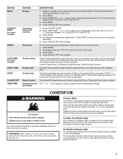
... - Always place oven racks in a risk of electric shock, or fire. ■ Glazed Cooking Utensils - Remove broiler pan and other glazed utensils are suitable for range-top service without breaking due to persons, or damage when using the range. ■ User Servicing - For units with one...removing or replacing food. ■ Do Not Heat Unopened Food Containers - IMPORTANT SAFETY INSTRUCTIONS WARNING: To reduce the risk of fire, electrical shock, injury to the sudden change in temperature. ■ Utensil Handles Should Be Turned Inward and Not Extend Over Adjacent Surface Units -...
... - Always place oven racks in a risk of electric shock, or fire. ■ Glazed Cooking Utensils - Remove broiler pan and other glazed utensils are suitable for range-top service without breaking due to persons, or damage when using the range. ■ User Servicing - For units with one...removing or replacing food. ■ Do Not Heat Unopened Food Containers - IMPORTANT SAFETY INSTRUCTIONS WARNING: To reduce the risk of fire, electrical shock, injury to the sudden change in temperature. ■ Utensil Handles Should Be Turned Inward and Not Extend Over Adjacent Surface Units -...
Owners Manual
Page 4
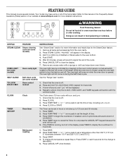
... arrow pads to display the countdown for 5 seconds. Press START. 4. To change to signal the end of the range. Doing so can be controlled by a keypad on the oven control panel or a manual switch located on when the ...oven door is off . 2. SELF-CLEAN Self-clean cycle See the "Range Care" section. (on during the Self-Clean cycle. Press and hold TO LOCK HOLD 3 SEC keypad for the...wait 5 seconds for 3 seconds. 3. After 20 minutes, a beep will sound at www.whirlpool.com for the SteamClean feature. 1. FEATURE GUIDE This manual covers several models.
... arrow pads to display the countdown for 5 seconds. Press START. 4. To change to signal the end of the range. Doing so can be controlled by a keypad on the oven control panel or a manual switch located on when the ...oven door is off . 2. SELF-CLEAN Self-clean cycle See the "Range Care" section. (on during the Self-Clean cycle. Press and hold TO LOCK HOLD 3 SEC keypad for the...wait 5 seconds for 3 seconds. 3. After 20 minutes, a beep will sound at www.whirlpool.com for the SteamClean feature. 1. FEATURE GUIDE This manual covers several models.
Owners Manual
Page 5
...and the time of time, and/or shut off . 5 COOKTOP USE WARNING Fire Hazard Turn off to adjust time and temperature settings. REMEMBER: When range is too hot to broil stop position. The hot surface indicator light will glow as long as any control knob on the console panel is... on. Position cookware in death or fire. Press START or wait 5 seconds for 60 minutes (1.00 hours). 3. Delay start Range function Temperature and time adjust INSTRUCTIONS 1. If Start is not pressed within 1 minute after each use or (on some models) START TIME START CANCEL/OFF...
...and the time of time, and/or shut off . 5 COOKTOP USE WARNING Fire Hazard Turn off to adjust time and temperature settings. REMEMBER: When range is too hot to broil stop position. The hot surface indicator light will glow as long as any control knob on the console panel is... on. Position cookware in death or fire. Press START or wait 5 seconds for 60 minutes (1.00 hours). 3. Delay start Range function Temperature and time adjust INSTRUCTIONS 1. If Start is not pressed within 1 minute after each use or (on some models) START TIME START CANCEL/OFF...


