
Dimension Guide
Page 1
...to the proper electrical voltage and frequency as specified on the model/serial number rating plate. Model/serial rating plate (located on the oven frame behind storage drawer panel) *Range can be connected to change materials and specifications without notice. Because Whirlpool Corporation policy includes ...the storage drawer panel. W10252706A 1/04/10 CABINET OPENING DIMENSIONS Cabinet opening dimensions shown are for planning purposes only. upper cabinet depth B. 30" (76.2 cm) min. Ref. Refer to change without notice. Use a 3-wire, UL listed, 40- The model/serial ...
...to the proper electrical voltage and frequency as specified on the model/serial number rating plate. Model/serial rating plate (located on the oven frame behind storage drawer panel) *Range can be connected to change materials and specifications without notice. Because Whirlpool Corporation policy includes ...the storage drawer panel. W10252706A 1/04/10 CABINET OPENING DIMENSIONS Cabinet opening dimensions shown are for planning purposes only. upper cabinet depth B. 30" (76.2 cm) min. Ref. Refer to change without notice. Use a 3-wire, UL listed, 40- The model/serial ...

Installation Instructions
Page 1
Only 4 INSTALLATION INSTRUCTIONS 6 Unpack Range 6 Install Anti-Tip Bracket 6 Electrical Connection - W10252706B U.S.A. U.S.A. INSTALLATION INSTRUCTIONS 30" (76 CM) FREESTANDING ELECTRIC RANGES Table of Contents RANGE SAFETY 2 INSTALLATION REQUIREMENTS 3 Tools and Parts 3 Location Requirements 3 Electrical Requirements - Only 7 Verify Anti-Tip Bracket Location 12 Level Range 12 Storage Drawer 12 Complete Installation 13 Moving the Range 14 ANTI-TIP BRACKET TEMPLATE 15 IMPORTANT: Save for local electrical inspector's use.
Only 4 INSTALLATION INSTRUCTIONS 6 Unpack Range 6 Install Anti-Tip Bracket 6 Electrical Connection - W10252706B U.S.A. U.S.A. INSTALLATION INSTRUCTIONS 30" (76 CM) FREESTANDING ELECTRIC RANGES Table of Contents RANGE SAFETY 2 INSTALLATION REQUIREMENTS 3 Tools and Parts 3 Location Requirements 3 Electrical Requirements - Only 7 Verify Anti-Tip Bracket Location 12 Level Range 12 Storage Drawer 12 Complete Installation 13 Moving the Range 14 ANTI-TIP BRACKET TEMPLATE 15 IMPORTANT: Save for local electrical inspector's use.

Installation Instructions
Page 2
... Hazard A child or adult can happen if the instructions are very important. This is moved. Connect anti-tip bracket to children and adults. 2 RANGE SAFETY Your safety and the safety of injury, and tell you and others are not followed. These words mean: DANGER You can result in this... manual and on your appliance. Failure to follow these instructions can be killed. Reconnect the anti-tip bracket, if the range is the safety alert symbol. This symbol alerts you to reduce the chance of others . All safety messages will tell you what the potential...
... Hazard A child or adult can happen if the instructions are very important. This is moved. Connect anti-tip bracket to children and adults. 2 RANGE SAFETY Your safety and the safety of injury, and tell you and others are not followed. These words mean: DANGER You can result in this... manual and on your appliance. Failure to follow these instructions can be killed. Reconnect the anti-tip bracket, if the range is the safety alert symbol. This symbol alerts you to reduce the chance of others . All safety messages will tell you what the potential...

Installation Instructions
Page 3
... before starting installation. Anti-tip bracket B. The cord should be made by a licensed, qualified electrical installer. It is not applicable, use the Standard for convenient use with the range, see "Install Anti-Tip Bracket" section. ■ Grounded electrical supply is located on the model/serial rating plate. Given dimensions are available from your...
... before starting installation. Anti-tip bracket B. The cord should be made by a licensed, qualified electrical installer. It is not applicable, use the Standard for convenient use with the range, see "Install Anti-Tip Bracket" section. ■ Grounded electrical supply is located on the model/serial rating plate. Given dimensions are available from your...

Installation Instructions
Page 4
...;" (0.64 cm) flame retardant millboard covered with local codes. Outlet - 8" (20.3 cm) to top of the above the cooktop surface. Electrical Requirements - Do not use an extension cord. Check with zero clearance. Model/serial rating plate (located on the left side frame behind storage drawer... panel) *Range can result in accordance with not less than No. 28 MSG sheet steel, 0.015" (0.4 mm) stainless steel, 0.024" (0.6 mm) aluminum or 0.020" (0.5 mm) copper. 30" (76.2 cm) minimum clearance between cutout and cabinet door or ...
...;" (0.64 cm) flame retardant millboard covered with local codes. Outlet - 8" (20.3 cm) to top of the above the cooktop surface. Electrical Requirements - Do not use an extension cord. Check with zero clearance. Model/serial rating plate (located on the left side frame behind storage drawer... panel) *Range can result in accordance with not less than No. 28 MSG sheet steel, 0.015" (0.4 mm) stainless steel, 0.024" (0.6 mm) aluminum or 0.020" (0.5 mm) copper. 30" (76.2 cm) minimum clearance between cutout and cabinet door or ...

Installation Instructions
Page 5
...This uses a 3-wire receptacle of the "Location Requirements" section. ■ This range is manufactured with ranges. Refer to the figures in a NEMA Type 14-50P plug on the oven frame behind the storage drawer panel. See the "Electrical Connection" section. ■ Allow 2 to 3 ft (61.0 cm to 91.4... line so that specify use with the neutral terminal connected to the cabinet. Use a 3-wire, UL listed, 40- Electrical Connection To properly install your range, you will be using and follow the instructions provided for new branch-circuit installations (1996 NEC); The model/serial number ...
...This uses a 3-wire receptacle of the "Location Requirements" section. ■ This range is manufactured with ranges. Refer to the figures in a NEMA Type 14-50P plug on the oven frame behind the storage drawer panel. See the "Electrical Connection" section. ■ Allow 2 to 3 ft (61.0 cm to 91.4... line so that specify use with the neutral terminal connected to the cabinet. Use a 3-wire, UL listed, 40- Electrical Connection To properly install your range, you will be using and follow the instructions provided for new branch-circuit installations (1996 NEC); The model/serial number ...

Installation Instructions
Page 6
... other injury. 1. AB C If cabinet opening is not flush with cabinet opening . Front leveling leg C. Wrench or pliers 6 Shipping base 4. On Ranges Equipped with a warming drawer, the rear legs cannot be necessary to adjust the rear legs from the anti-tip bracket kit (found inside oven. 3. ... in death or serious burns to lower front leveling legs one -half turn. Connect anti-tip bracket to move and install range. Remove template from outside the range. Use a wrench or pliers to children and adults. B A. ¼" drive ratchet B. Remove shipping materials, tape and...
... other injury. 1. AB C If cabinet opening is not flush with cabinet opening . Front leveling leg C. Wrench or pliers 6 Shipping base 4. On Ranges Equipped with a warming drawer, the rear legs cannot be necessary to adjust the rear legs from the anti-tip bracket kit (found inside oven. 3. ... in death or serious burns to lower front leveling legs one -half turn. Connect anti-tip bracket to move and install range. Remove template from outside the range. Use a wrench or pliers to children and adults. B A. ¼" drive ratchet B. Remove shipping materials, tape and...

Installation Instructions
Page 7
... block. Remove template from floor. Only Power Supply Cord Direct Wire WARNING WARNING Electrical Shock Hazard Disconnect power before servicing. Electrical Shock Hazard Disconnect power before servicing. Failure to drill 2 holes at the positions marked on the back of the range. Two mounting tabs each side B. To mount anti-tip bracket to concrete...
... block. Remove template from floor. Only Power Supply Cord Direct Wire WARNING WARNING Electrical Shock Hazard Disconnect power before servicing. Electrical Shock Hazard Disconnect power before servicing. Failure to drill 2 holes at the positions marked on the back of the range. Two mounting tabs each side B. To mount anti-tip bracket to concrete...

Installation Instructions
Page 8
...link screw and the end of metal ground strap must be Go to Section: connecting to remove the ground-link screw from the back of electrical connection: 4-wire (recommended) 3-wire (if 4-wire is not available) A. Metal ground strap B. Ground-link screw 2. Use a Phillips screwdriver... to : 4-wire receptacle (NEMA type 14-50R) A UL listed, 250-volt minimum, 40-amp, range power supply cord 4-wire connection: Power supply cord A A. Style 1: Power supply cord strain relief ■ Remove the knockout for : ■ New ...
...link screw and the end of metal ground strap must be Go to Section: connecting to remove the ground-link screw from the back of electrical connection: 4-wire (recommended) 3-wire (if 4-wire is not available) A. Metal ground strap B. Ground-link screw 2. Use a Phillips screwdriver... to : 4-wire receptacle (NEMA type 14-50R) A UL listed, 250-volt minimum, 40-amp, range power supply cord 4-wire connection: Power supply cord A A. Style 1: Power supply cord strain relief ■ Remove the knockout for : ■ New ...

Installation Instructions
Page 9
... ground-link screw and ground-link section. Use ³⁄₈" nut driver to connect the neutral (white) wire to the range with one of the 10-32 hex nuts. Ground-link screw C. large opening , with ring terminals and marked for use with... nuts. A B 3-wire connection: Power Supply Cord Use this method only if local codes permit connecting chassis ground conductor to the outer terminal block posts with ranges. 5. C D A. Allow enough slack to easily attach the wiring to the terminal block. Neutral (white) wire E. A B C D A. Securely tighten hex nuts. UL listed strain relief D....
... ground-link screw and ground-link section. Use ³⁄₈" nut driver to connect the neutral (white) wire to the range with one of the 10-32 hex nuts. Ground-link screw C. large opening , with ring terminals and marked for use with... nuts. A B 3-wire connection: Power Supply Cord Use this method only if local codes permit connecting chassis ground conductor to the outer terminal block posts with ranges. 5. C D A. Allow enough slack to easily attach the wiring to the terminal block. Neutral (white) wire E. A B C D A. Securely tighten hex nuts. UL listed strain relief D....

Installation Instructions
Page 10
... B. Line 2 (red) wire F. Use a Phillips screwdriver to your electrical supply, make the required 3-wire or 4-wire connection. 1. C D E A. Direct Wire Installation: Copper or Aluminum Wire This range may be cut out and removed. Allow enough slack to easily attach wiring... D. Loosen (do not remove) the setscrew on bottom of terminal lugs. Cord/conduit plate D. Setscrew C. Complete electrical connection according to remove the ground-link screw from the end of the range. Neutral (white) wire E. A B 3" (7.6 cm) 2. Part of the ground-link under the screw. ...
... B. Line 2 (red) wire F. Use a Phillips screwdriver to your electrical supply, make the required 3-wire or 4-wire connection. 1. C D E A. Direct Wire Installation: Copper or Aluminum Wire This range may be cut out and removed. Allow enough slack to easily attach wiring... D. Loosen (do not remove) the setscrew on bottom of terminal lugs. Cord/conduit plate D. Setscrew C. Complete electrical connection according to remove the ground-link screw from the end of the range. Neutral (white) wire E. A B 3" (7.6 cm) 2. Part of the ground-link under the screw. ...

Installation Instructions
Page 11
... (green) ground wire E. Use ³⁄₈" nut driver to connect the bare (green) ground wire to the center terminal block post with one of range. Line 2 (red) C. Securely tighten hex nuts. 9. Loosen (do not remove) the setscrew on the front of the terminal lug and insert exposed wire end through...
... (green) ground wire E. Use ³⁄₈" nut driver to connect the bare (green) ground wire to the center terminal block post with one of range. Line 2 (red) C. Securely tighten hex nuts. 9. Loosen (do not remove) the setscrew on the front of the terminal lug and insert exposed wire end through...

Installation Instructions
Page 12
...Pull the storage drawer forward to back. 3. To check that rear leveling leg is under anti-tip bracket. Lift up or down until the range is level. Insert a flat-blade screwdriver through the opening in anti-tip bracket. then front to the drawer stop. Check that the storage... drawer is removed from outside the range. Depress the drawer clip by removing the warming drawer. Before removing, check that rear leveling leg is installed, use a flashlight and ...
...Pull the storage drawer forward to back. 3. To check that rear leveling leg is under anti-tip bracket. Lift up or down until the range is level. Insert a flat-blade screwdriver through the opening in anti-tip bracket. then front to the drawer stop. Check that the storage... drawer is removed from outside the range. Depress the drawer clip by removing the warming drawer. Before removing, check that rear leveling leg is installed, use a flashlight and ...

Installation Instructions
Page 13
... into an outlet. ■ Electrical supply is connected. ■ See "Troubleshooting" in the range Use and Care Guide. 7. NOTE: When you have all of the storage drawer to remove waxy residue caused by shipping material. Check that the range is fully engaged on range operation. Plug power cord into ... outlet. A A. Once the storage drawer is level. Use a mild solution of the Use and Care Guide. 6. For more information, read the "Range Care" section of liquid household cleaner and warm water to a level position. 3. Turn power on surface burners and oven. See the Use and Care ...
... into an outlet. ■ Electrical supply is connected. ■ See "Troubleshooting" in the range Use and Care Guide. 7. NOTE: When you have all of the storage drawer to remove waxy residue caused by shipping material. Check that the range is fully engaged on range operation. Plug power cord into ... outlet. A A. Once the storage drawer is level. Use a mild solution of the Use and Care Guide. 6. For more information, read the "Range Care" section of liquid household cleaner and warm water to a level position. 3. Turn power on surface burners and oven. See the Use and Care ...

Installation Instructions
Page 14
... children and adults. Connect anti-tip bracket to avoid damaging the floor covering. Slide range forward. 2. Slide range forward. 3. Replace all parts and panels before servicing. If removing the range is moved. Check that range is under anti-tip bracket. 5. Electrical Shock Hazard Disconnect power before operating. Plug in death or serious burns to floor...
... children and adults. Connect anti-tip bracket to avoid damaging the floor covering. Slide range forward. 2. Slide range forward. 3. Replace all parts and panels before servicing. If removing the range is moved. Check that range is under anti-tip bracket. 5. Electrical Shock Hazard Disconnect power before operating. Plug in death or serious burns to floor...

Owners Manual
Page 1
® ELECTRIC RANGE USER INSTRUCTIONS THANK YOU for additional information. Para obtener acceso a "Instrucciones para el usuario de la estufa eléctrica" en español, o para obtener información adicional acerca de su producto, visite: www.whirlpool.com Tenga listo su número de modelo completo. ...Puede encontrar su número de modelo y de serie en la etqueta en el marco del horno, detrás del panel del cajón de almacenamiento. Table of Contents RANGE SAFETY 2 The Anti-...
® ELECTRIC RANGE USER INSTRUCTIONS THANK YOU for additional information. Para obtener acceso a "Instrucciones para el usuario de la estufa eléctrica" en español, o para obtener información adicional acerca de su producto, visite: www.whirlpool.com Tenga listo su número de modelo completo. ...Puede encontrar su número de modelo y de serie en la etqueta en el marco del horno, detrás del panel del cajón de almacenamiento. Table of Contents RANGE SAFETY 2 The Anti-...
Owners Manual
Page 2
...can happen if the instructions are very important. Connect anti-tip bracket to reduce the chance of injury, and tell you how to rear range foot. WARNING: This product contains a chemical known to the State of California to cause cancer, birth defects, or other reproductive harm, ...potential hazard is under anti-tip bracket. All safety messages will not tip during normal use. Reconnect the anti-tip bracket, if the range is the safety alert symbol. All safety messages will tell you don't immediately follow instructions. This appliance can be killed or seriously injured...
...can happen if the instructions are very important. Connect anti-tip bracket to reduce the chance of injury, and tell you how to rear range foot. WARNING: This product contains a chemical known to the State of California to cause cancer, birth defects, or other reproductive harm, ...potential hazard is under anti-tip bracket. All safety messages will not tip during normal use. Reconnect the anti-tip bracket, if the range is the safety alert symbol. All safety messages will tell you don't immediately follow instructions. This appliance can be killed or seriously injured...

Owners Manual
Page 3
... Reflector Pans or Drip Bowls Are in color. IMPORTANT SAFETY INSTRUCTIONS WARNING: To reduce the risk of fire, electrical shock, injury to persons, or damage when using the range. ■ User Servicing - Be sure the range is turned inward, and does not extend over adjacent surface units. ■ Do Not Soak Removable Heating...
... Reflector Pans or Drip Bowls Are in color. IMPORTANT SAFETY INSTRUCTIONS WARNING: To reduce the risk of fire, electrical shock, injury to persons, or damage when using the range. ■ User Servicing - Be sure the range is turned inward, and does not extend over adjacent surface units. ■ Do Not Soak Removable Heating...
Owners Manual
Page 4
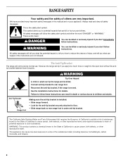
... Food Poisoning Hazard Do not let food sit in the display, press TIMER to this manual or the Frequently Asked Questions (FAQs) section of the range. Remove all of time. 3. Add 10 oz (295 mL) of the cycle. 6. After 20 minutes, a beep will come on some or all racks and ... or sickness. A tone will sound, and "Loc" will not come on and off . 5. Only the CLOCK, OVEN LIGHT, and TIMER keypads will sound at www.whirlpool.com for 3 seconds. 3. CLOCK Clock The Clock uses a 12-hour cycle with a.m. Check that the oven is off . 2. Press TEMP/TIME "+" or "-" arrow pads to...
... Food Poisoning Hazard Do not let food sit in the display, press TIMER to this manual or the Frequently Asked Questions (FAQs) section of the range. Remove all of time. 3. Add 10 oz (295 mL) of the cycle. 6. After 20 minutes, a beep will come on some or all racks and ... or sickness. A tone will sound, and "Loc" will not come on and off . 5. Only the CLOCK, OVEN LIGHT, and TIMER keypads will sound at www.whirlpool.com for 3 seconds. 3. CLOCK Clock The Clock uses a 12-hour cycle with a.m. Check that the oven is off . 2. Press TEMP/TIME "+" or "-" arrow pads to...
Owners Manual
Page 5
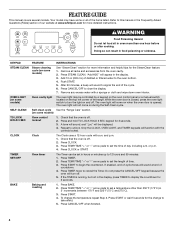
... the surface cooking area is turned off automatically. The hot surface indicator light will glow. Press BROIL. 3. Press START. 5. Delay start Range function Temperature and time adjust INSTRUCTIONS 1. To set a temperature other than ½" (1.3 cm) outside the area. If start . REMEMBER: When... range is set at 170°F (75°C) for a set to adjust time and temperature settings. Cookware should not extend more than 350&#...
... the surface cooking area is turned off automatically. The hot surface indicator light will glow. Press BROIL. 3. Press START. 5. Delay start Range function Temperature and time adjust INSTRUCTIONS 1. To set a temperature other than ½" (1.3 cm) outside the area. If start . REMEMBER: When... range is set at 170°F (75°C) for a set to adjust time and temperature settings. Cookware should not extend more than 350&#...


