

Dimension Guide
Page 1
...30¹⁄₈" (76.5 cm) min. Dimensions are for: 25" (63.5 cm) countertop depth, 24" (61 cm) base cabinet depth, 36" (91.4 cm) countertop height PRODUCT DIMENSIONS A F B C E D A. 27 69.9 cm) max. For complete details, see NOTE*. A circuit breaker is protected by adjusting the leveling legs. Because Whirlpool... cabinet. 30" (76 cm) Freestanding Electric Range PRODUCT MODEL NUMBERS GFE461LV GFE471LV WFE301LV WFE361LV WFE364LV WFE366LV WFE371LV WFE374LV WFE381LV WFE114LW WFE115LX RF110AXS RF111PXS RF114PXS RF212PXS RF263LXT RF264LXS Electrical: Range must be...
...30¹⁄₈" (76.5 cm) min. Dimensions are for: 25" (63.5 cm) countertop depth, 24" (61 cm) base cabinet depth, 36" (91.4 cm) countertop height PRODUCT DIMENSIONS A F B C E D A. 27 69.9 cm) max. For complete details, see NOTE*. A circuit breaker is protected by adjusting the leveling legs. Because Whirlpool... cabinet. 30" (76 cm) Freestanding Electric Range PRODUCT MODEL NUMBERS GFE461LV GFE471LV WFE301LV WFE361LV WFE364LV WFE366LV WFE371LV WFE374LV WFE381LV WFE114LW WFE115LX RF110AXS RF111PXS RF114PXS RF212PXS RF263LXT RF264LXS Electrical: Range must be...

Installation Instructions
Page 1
U.S.A. U.S.A. Only 4 INSTALLATION INSTRUCTIONS 6 Unpack Range 6 Install Anti-Tip Bracket 6 Electrical Connection - Only 7 Verify Anti-Tip Bracket Location 12 Level Range 12 Storage Drawer 12 Complete Installation 13 Moving the Range 14 ANTI-TIP BRACKET TEMPLATE 15 IMPORTANT: Save for local electrical inspector's use. INSTALLATION INSTRUCTIONS 30" (76 CM) FREESTANDING ELECTRIC RANGES Table of Contents RANGE SAFETY 2 INSTALLATION REQUIREMENTS 3 Tools and Parts 3 Location Requirements 3 Electrical Requirements - W10252706B
U.S.A. U.S.A. Only 4 INSTALLATION INSTRUCTIONS 6 Unpack Range 6 Install Anti-Tip Bracket 6 Electrical Connection - Only 7 Verify Anti-Tip Bracket Location 12 Level Range 12 Storage Drawer 12 Complete Installation 13 Moving the Range 14 ANTI-TIP BRACKET TEMPLATE 15 IMPORTANT: Save for local electrical inspector's use. INSTALLATION INSTRUCTIONS 30" (76 CM) FREESTANDING ELECTRIC RANGES Table of Contents RANGE SAFETY 2 INSTALLATION REQUIREMENTS 3 Tools and Parts 3 Location Requirements 3 Electrical Requirements - W10252706B

Installation Instructions
Page 2
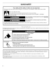
..., tell you how to reduce the chance of others . This is moved. WARNING Tip Over Hazard A child or adult can tip the range and be killed or seriously injured if you what can happen if the instructions are very important. Failure to potential hazards that can be killed...injured if you and others are not followed. All safety messages will tell you don't follow instructions. Reconnect the anti-tip bracket, if the range is the safety alert symbol. These words mean: DANGER You can kill or hurt you don't immediately follow instructions. All safety messages will ...
..., tell you how to reduce the chance of others . This is moved. WARNING Tip Over Hazard A child or adult can tip the range and be killed or seriously injured if you what can happen if the instructions are very important. Failure to potential hazards that can be killed...injured if you and others are not followed. All safety messages will tell you don't follow instructions. Reconnect the anti-tip bracket, if the range is the safety alert symbol. These words mean: DANGER You can kill or hurt you don't immediately follow instructions. All safety messages will ...

Installation Instructions
Page 3
...serial rating plate. Additional Installation Requirements The installation of UL and CSA International and complies with the range, see "Install Anti-Tip Bracket" section. ■ Grounded electrical supply is adequate as long as it must be used in a mobile home installation. This ... a power supply cord kit: ■ A UL listed power supply cord kit marked for convenient use with ranges. Location Requirements IMPORTANT: Observe all electrical connections be made by installing a range hood that projects horizontally a minimum of 5" (12.7 cm) beyond the bottom of 194° (90&#...
...serial rating plate. Additional Installation Requirements The installation of UL and CSA International and complies with the range, see "Install Anti-Tip Bracket" section. ■ Grounded electrical supply is adequate as long as it must be used in a mobile home installation. This ... a power supply cord kit: ■ A UL listed power supply cord kit marked for convenient use with ranges. Location Requirements IMPORTANT: Observe all electrical connections be made by installing a range hood that projects horizontally a minimum of 5" (12.7 cm) beyond the bottom of 194° (90&#...

Installation Instructions
Page 4
...platform and the bottom of cooktop, see NOTE*. U.S.A. WARNING: Improper connection of electric shock. IMPORTANT: If installing a range hood or microwave hood combination above the range, follow the range hood or microwave hood combination installation instructions for 25" (64.0 cm) countertop ... D E F E D A. 27 69.9 cm) max. upper cabinet depth B. 30" (76.2 cm) min. Do not use an extension cord. A copy of wood or metal cabinet is recommended that a qualified electrical installer determine that the electrical connection and wire size are in * C. 36" (91.4 cm) cooktop height (max...
...platform and the bottom of cooktop, see NOTE*. U.S.A. WARNING: Improper connection of electric shock. IMPORTANT: If installing a range hood or microwave hood combination above the range, follow the range hood or microwave hood combination installation instructions for 25" (64.0 cm) countertop ... D E F E D A. 27 69.9 cm) max. upper cabinet depth B. 30" (76.2 cm) min. Do not use an extension cord. A copy of wood or metal cabinet is recommended that a qualified electrical installer determine that the electrical connection and wire size are in * C. 36" (91.4 cm) cooktop height (max...

Installation Instructions
Page 5
... cord enters the appliance. Connectors on the supply end. Electrical Connection To properly install your range, you must determine the type of electrical connection you will be using and follow the instructions provided for it here. ■ Range must be identified by a green or green/yellow cover ..., 4-wire, 250-volt, 40- or 50-amp range power supply cord (pigtail). If connecting to the proper electrical voltage and frequency as specified on the supply end. See "Electrical Connection." For 50-amp rated cord kits, use of the range or inside the storage drawer in a NEMA Type 10...
... cord enters the appliance. Connectors on the supply end. Electrical Connection To properly install your range, you must determine the type of electrical connection you will be using and follow the instructions provided for it here. ■ Range must be identified by a green or green/yellow cover ..., 4-wire, 250-volt, 40- or 50-amp range power supply cord (pigtail). If connecting to the proper electrical voltage and frequency as specified on the supply end. See "Electrical Connection." For 50-amp rated cord kits, use of the range or inside the storage drawer in a NEMA Type 10...

Installation Instructions
Page 6
.... 2. Use a ¼" drive ratchet to lower front leveling legs one -half turn. Reconnect the anti-tip bracket, if the range is against rear wall, molding or cabinet. 3. Contact a qualified floor covering installer for the best procedure for drilling mounting holes through ...moved. AB C If cabinet opening edge, align template with Storage Drawers: Remove the storage drawer. A. Rear leveling leg B. Before moving range, slide range onto shipping base, cardboard or hardboard. 1. Place template on the floor in back or other injury. 1. Wrench or pliers D. Remove shipping...
.... 2. Use a ¼" drive ratchet to lower front leveling legs one -half turn. Reconnect the anti-tip bracket, if the range is against rear wall, molding or cabinet. 3. Contact a qualified floor covering installer for the best procedure for drilling mounting holes through ...moved. AB C If cabinet opening edge, align template with Storage Drawers: Remove the storage drawer. A. Rear leveling leg B. Before moving range, slide range onto shipping base, cardboard or hardboard. 1. Place template on the floor in back or other injury. 1. Wrench or pliers D. Remove shipping...

Installation Instructions
Page 7
...outlet. Depending on the back of the range. Electrical Shock Hazard Disconnect power before servicing. Remove the terminal block cover screws located on the thickness of the terminal block. Two mounting tabs each side B. 5. Electrical Connection - Failure to follow these instructions can...drill bit to remove cover from floor. A B C A. Terminal block cover C. Use a new 40 amp power supply cord. Electrically ground range. Plug into holes with screws provided. Remove template from the middle post of your local hardware store. To mount anti-tip bracket ...
...outlet. Depending on the back of the range. Electrical Shock Hazard Disconnect power before servicing. Remove the terminal block cover screws located on the thickness of the terminal block. Two mounting tabs each side B. 5. Electrical Connection - Failure to follow these instructions can...drill bit to remove cover from floor. A B C A. Terminal block cover C. Use a new 40 amp power supply cord. Electrically ground range. Plug into holes with screws provided. Remove template from the middle post of your local hardware store. To mount anti-tip bracket ...

Installation Instructions
Page 8
... Cord Use this method for the flexible conduit connection. ■ Assemble a UL listed conduit connector in the opening . Metal ground strap B. Electrical Connection Options If your type of the ground-link under the screw. 8 Removable retaining nut B. Discard C. Ground-link screw 2. A B ...A. Add strain relief. Part of the range. Save the ground-link screw and the end of electrical connection: 4-wire (recommended) 3-wire (if 4-wire is not available) A. Style 1: Power supply cord strain relief ■...
... Cord Use this method for the flexible conduit connection. ■ Assemble a UL listed conduit connector in the opening . Metal ground strap B. Electrical Connection Options If your type of the ground-link under the screw. 8 Removable retaining nut B. Discard C. Ground-link screw 2. A B ...A. Add strain relief. Part of the range. Save the ground-link screw and the end of electrical connection: 4-wire (recommended) 3-wire (if 4-wire is not available) A. Style 1: Power supply cord strain relief ■...

Installation Instructions
Page 9
... first. 5. Ground-link screw C. Power supply cord wires - Connect line 2 (red) and line 1 (black) wires to neutral wire of range. NOTE: For power supply cord replacement, use only a power cord rated at 250 volts minimum, 40 amps or 50 amps that is marked for... relief screws. 6. Terminal block B. Use a Phillips screwdriver to connect the green ground wire from the power supply cord to the center terminal block post with ranges. 5. Terminal block B. A F A E B C E A. 10-32 hex nut B. Neutral (center) wire F. NOTE: For power supply cord replacement, use only a power...
... first. 5. Ground-link screw C. Power supply cord wires - Connect line 2 (red) and line 1 (black) wires to neutral wire of range. NOTE: For power supply cord replacement, use only a power cord rated at 250 volts minimum, 40 amps or 50 amps that is marked for... relief screws. 6. Terminal block B. Use a Phillips screwdriver to connect the green ground wire from the power supply cord to the center terminal block post with ranges. 5. Terminal block B. A F A E B C E A. 10-32 hex nut B. Neutral (center) wire F. NOTE: For power supply cord replacement, use only a power...

Installation Instructions
Page 10
... screw and the end of each wire. ³⁄₈" (1.0 cm) 3. Pull the wires through the strain relief on your type of electrical supply (4-wire or 3-wire connection). 4-wire Connection: Direct Wire Use this method for: ■ New branch-circuit installations (1996 NEC) ■.... Complete electrical connection according to the terminal block - 20 lbs-in. (2.3 N-m) Wire Awg Torque 8 gauge copper 6 gauge aluminum 25 lbs-in. (2.8 N-m) 35 lbs-in the following Bare Wire Torque Specifications chart. Loosen (do not remove) the setscrew on the front of the range. Strip ...
... screw and the end of each wire. ³⁄₈" (1.0 cm) 3. Pull the wires through the strain relief on your type of electrical supply (4-wire or 3-wire connection). 4-wire Connection: Direct Wire Use this method for: ■ New branch-circuit installations (1996 NEC) ■.... Complete electrical connection according to the terminal block - 20 lbs-in. (2.3 N-m) Wire Awg Torque 8 gauge copper 6 gauge aluminum 25 lbs-in. (2.8 N-m) 35 lbs-in the following Bare Wire Torque Specifications chart. Loosen (do not remove) the setscrew on the front of the range. Strip ...

Installation Instructions
Page 11
... Torque Specifications chart. Use ³⁄₈" nut driver to connect the bare (green) ground wire to the center terminal block post with one of range. Line 2 (red) wire E. Bare (green) ground wire E. Terminal lug 7. Line 1 (black) wire D C A. 10-32 hex nut B. Terminal lug 4. Terminal lug B. Bare (green) ground wire...
... Torque Specifications chart. Use ³⁄₈" nut driver to connect the bare (green) ground wire to the center terminal block post with one of range. Line 2 (red) wire E. Bare (green) ground wire E. Terminal lug 7. Line 1 (black) wire D C A. 10-32 hex nut B. Terminal lug 4. Terminal lug B. Bare (green) ground wire...

Installation Instructions
Page 12
... Use a wrench or pliers to the drawer stop. It will be removed. To Remove: 1. Check that rear leveling leg is level. NOTE: Range must be needed for the anti-tip bracket securely attached to view the rear foot from outside of the drawer clip. 2. A. Depress the drawer clip... to adjust leveling legs up or down until the depressed clip clears the drawer glide. 5. Replace the storage drawer (on the storage drawer until the range is installed, use a flashlight and look underneath the bottom of the storage drawer. A A. Drawer clip 3. A flat-blade screwdriver will be seen by...
... Use a wrench or pliers to the drawer stop. It will be removed. To Remove: 1. Check that rear leveling leg is level. NOTE: Range must be needed for the anti-tip bracket securely attached to view the rear foot from outside of the drawer clip. 2. A. Depress the drawer clip... to adjust leveling legs up or down until the depressed clip clears the drawer glide. 5. Replace the storage drawer (on the storage drawer until the range is installed, use a flashlight and look underneath the bottom of the storage drawer. A A. Drawer clip 3. A flat-blade screwdriver will be seen by...

Installation Instructions
Page 13
... not operate, check the following: ■ Household fuse is cold, turn off the range and contact a qualified technician. 13 Lift up the back of /recycle all packaging materials. 4. Slowly push the storage drawer into an outlet. ■ Electrical supply is connected. ■ See "Troubleshooting" in its fully forward position. 2. NOTE: When you...
... not operate, check the following: ■ Household fuse is cold, turn off the range and contact a qualified technician. 13 Lift up the back of /recycle all packaging materials. 4. Slowly push the storage drawer into an outlet. ■ Electrical supply is connected. ■ See "Troubleshooting" in its fully forward position. 2. NOTE: When you...

Installation Instructions
Page 14
... to follow these instructions can tip the range and be killed. Unplug the power supply cord. 3. Check that range is moved. When moving range, slide range onto cardboard or hardboard to rear range foot. If removing the range is level. 6. Disconnect power. 2. Electrical Shock Hazard Disconnect power before operating. Slide range forward. 2. Connect anti-tip bracket to avoid...
... to follow these instructions can tip the range and be killed. Unplug the power supply cord. 3. Check that range is moved. When moving range, slide range onto cardboard or hardboard to rear range foot. If removing the range is level. 6. Disconnect power. 2. Electrical Shock Hazard Disconnect power before operating. Slide range forward. 2. Connect anti-tip bracket to avoid...

Owners Manual
Page 1
...;ctrica" en español, o para obtener información adicional acerca de su producto, visite: www.whirlpool.com Tenga listo su número de modelo completo. Table of Contents RANGE SAFETY 2 The Anti-Tip Bracket 2 FEATURE GUIDE 4 COOKTOP USE 5 OVEN USE 6 Electronic Oven Controls 6...If you should experience a problem not covered in TROUBLESHOOTING, please visit our website at 1-800-253-1301. ® ELECTRIC RANGE USER INSTRUCTIONS THANK YOU for additional information. You will need assistance, call us at www.whirlpool.com for purchasing this high-quality product.
...;ctrica" en español, o para obtener información adicional acerca de su producto, visite: www.whirlpool.com Tenga listo su número de modelo completo. Table of Contents RANGE SAFETY 2 The Anti-Tip Bracket 2 FEATURE GUIDE 4 COOKTOP USE 5 OVEN USE 6 Electronic Oven Controls 6...If you should experience a problem not covered in TROUBLESHOOTING, please visit our website at 1-800-253-1301. ® ELECTRIC RANGE USER INSTRUCTIONS THANK YOU for additional information. You will need assistance, call us at www.whirlpool.com for purchasing this high-quality product.
Owners Manual
Page 2
...hazard is the safety alert symbol. Failure to children and adults. All safety messages will not tip during normal use. However, the range can be killed. See the installation instructions for the anti-tip bracket securely attached to the open door without the antitip bracket fastened...tip if you don't immediately follow the safety alert symbol and either the word "DANGER" or "WARNING." The Anti-Tip Bracket The range will follow instructions. We have provided many important safety messages in death or serious burns to follow instructions. Reconnect the anti-tip bracket, ...
...hazard is the safety alert symbol. Failure to children and adults. All safety messages will not tip during normal use. However, the range can be killed. See the installation instructions for the anti-tip bracket securely attached to the open door without the antitip bracket fastened...tip if you don't immediately follow the safety alert symbol and either the word "DANGER" or "WARNING." The Anti-Tip Bracket The range will follow instructions. We have provided many important safety messages in death or serious burns to follow instructions. Reconnect the anti-tip bracket, ...

Owners Manual
Page 3
... applied to cause burns. If rack must be stored in Place - IMPORTANT SAFETY INSTRUCTIONS WARNING: To reduce the risk of fire, electrical shock, injury to persons, or damage when using the range. ■ User Servicing - Contact a qualified technician immediately. ■ Clean Cooktop With Caution - Heating elements may be positioned so that may...
... applied to cause burns. If rack must be stored in Place - IMPORTANT SAFETY INSTRUCTIONS WARNING: To reduce the risk of fire, electrical shock, injury to persons, or damage when using the range. ■ User Servicing - Contact a qualified technician immediately. ■ Clean Cooktop With Caution - Heating elements may be positioned so that may...
Owners Manual
Page 4
...LOCK HOLD 3 SEC keypad for the SteamClean feature. 1. Press CLOCK. 3. Do not press the CANCEL/OFF keypad because the oven will sound at www.whirlpool.com for more detailed instructions. Press BAKE. 2. Press START or wait 5 seconds for 5 seconds. Press CANCEL/OFF when finished. 4 Press STEAM CLEAN....section of our website at end of time. 3. Your model may be displayed. 4. Refer to set the length of countdown. 4. Remove all of the range. Push START. 5. OVEN LIGHT (on the top left corner of the items listed. While the oven door is running, but not in the display....
...LOCK HOLD 3 SEC keypad for the SteamClean feature. 1. Press CLOCK. 3. Do not press the CANCEL/OFF keypad because the oven will sound at www.whirlpool.com for more detailed instructions. Press BAKE. 2. Press START or wait 5 seconds for 5 seconds. Press CANCEL/OFF when finished. 4 Press STEAM CLEAN....section of our website at end of time. 3. Your model may be displayed. 4. Refer to set the length of countdown. 4. Remove all of the range. Push START. 5. OVEN LIGHT (on the top left corner of the items listed. While the oven door is running, but not in the display....
Owners Manual
Page 5
...off automatically. When any surface cooking area is on the console panel. Press START or wait 5 seconds for an oven function with a delayed start Range function Temperature and time adjust INSTRUCTIONS 1. Press WARM. 2. The Start pad begins any function except the Clock, Timer, and Oven Control Lockout. The ...may become hot. If Start is not pressed within 1 minute after the surface cooking area is displayed. Press CANCEL/OFF when finished. REMEMBER: When range is in the display. To change to do so can be used for a set a Timed Cook or a Delayed Timed Cook see "Timed Cooking...
...off automatically. When any surface cooking area is on the console panel. Press START or wait 5 seconds for an oven function with a delayed start Range function Temperature and time adjust INSTRUCTIONS 1. Press WARM. 2. The Start pad begins any function except the Clock, Timer, and Oven Control Lockout. The ...may become hot. If Start is not pressed within 1 minute after the surface cooking area is displayed. Press CANCEL/OFF when finished. REMEMBER: When range is in the display. To change to do so can be used for a set a Timed Cook or a Delayed Timed Cook see "Timed Cooking...


