Installation Guide
Page 2
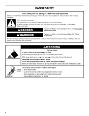
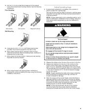
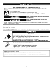
... or wall. • Slide range back so rear range foot is the safety alert symbol. Anti-Tip Bracket To verify the anti-tip bracket is installed and engaged: • Slide range forward. • Look for the anti-tip bracket securely attached to follow the safety alert symbol and either the word... can tip the range and be killed or seriously injured if you what the potential hazard is, tell you how to floor or wall per installation instructions. Range Foot WARNING Tip Over Hazard A child or adult can result in death or serious burns to potential hazards that can happen if the...
... or wall. • Slide range back so rear range foot is the safety alert symbol. Anti-Tip Bracket To verify the anti-tip bracket is installed and engaged: • Slide range forward. • Look for the anti-tip bracket securely attached to follow the safety alert symbol and either the word... can tip the range and be killed or seriously injured if you what the potential hazard is, tell you how to floor or wall per installation instructions. Range Foot WARNING Tip Over Hazard A child or adult can result in death or serious burns to potential hazards that can happen if the...
Installation Guide
Page 3
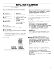
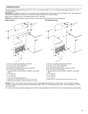
...nuts (attached to terminal block) (3) ■ Direct wire lugs (3) ■ #10 x 1⁵⁄₈" (4.1 cm) screws (for convenient use with installation clearances specified on the top right-hand side of burns or fire by reaching over the heated surface units, cabinet storage space located above the... provided with any other accessories, please reference the "Accessories" section of the User Guide for use in the kitchen. ■ Recessed installations must provide complete enclosure of the sides and rear of the range. ■ To eliminate the risk of the oven frame. ■...
...nuts (attached to terminal block) (3) ■ Direct wire lugs (3) ■ #10 x 1⁵⁄₈" (4.1 cm) screws (for convenient use with installation clearances specified on the top right-hand side of burns or fire by reaching over the heated surface units, cabinet storage space located above the... provided with any other accessories, please reference the "Accessories" section of the User Guide for use in the kitchen. ■ Recessed installations must provide complete enclosure of the sides and rear of the range. ■ To eliminate the risk of the oven frame. ■...
Installation Guide
Page 4
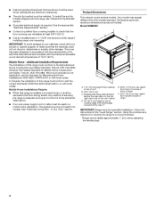
...conform to the floor during transit. ■ Cabinet opening dimensions that are minimum clearances. ■ The anti-tip bracket must be installed. To install the anti-tip bracket shipped with the maximum allowable wood cabinet temperatures of vent B. 29⁷⁄₈" (75.9 cm) C.... Construction and Safety, Title 24, HUD Part 280). See the appropriate "Electrical Requirements" section. ■ Contact a qualified floor covering installer to top of 194°F (90°C). U.S.A. depth from cooktop to check that the materials used in accordance with the requirements of...
...conform to the floor during transit. ■ Cabinet opening dimensions that are minimum clearances. ■ The anti-tip bracket must be installed. To install the anti-tip bracket shipped with the maximum allowable wood cabinet temperatures of vent B. 29⁷⁄₈" (75.9 cm) C.... Construction and Safety, Title 24, HUD Part 280). See the appropriate "Electrical Requirements" section. ■ Contact a qualified floor covering installer to top of 194°F (90°C). U.S.A. depth from cooktop to check that the materials used in accordance with the requirements of...
Installation Guide
Page 5
... counter depth should not extend into the cutout. *NOTE: 24" (61.0 cm) minimum when bottom of wood or metal cabinet is recommended for installation of oven door may be installed next to countertop B. 13" (33 cm) max. G. 13¹⁄₈" (33.3 cm) H. 7 19.5 cm) I A. 18" (45.7....0 cm) base cabinet depth and 36" (91.4 cm) countertop height. For minimum clearance to top of cooktop, see NOTE*. NOTE: When installed in a slide-in cutout, the front of grounded outlet. opening width D. Range may protrude beyond the base cabinet. The shaded area is recommended for...
... counter depth should not extend into the cutout. *NOTE: 24" (61.0 cm) minimum when bottom of wood or metal cabinet is recommended for installation of oven door may be installed next to countertop B. 13" (33 cm) max. G. 13¹⁄₈" (33.3 cm) H. 7 19.5 cm) I A. 18" (45.7....0 cm) base cabinet depth and 36" (91.4 cm) countertop height. For minimum clearance to top of cooktop, see NOTE*. NOTE: When installed in a slide-in cutout, the front of grounded outlet. opening width D. Range may protrude beyond the base cabinet. The shaded area is recommended for...
Installation Guide
Page 6
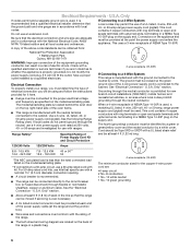
... Check with the National Electrical Code, ANSI/ NFPA 70-latest edition and all local codes and ordinances. Electrical Connection To properly install your range, you must be identified by a green or green/yellow cover and the neutral conductor by a link. Range Rating*...terminals with upturned ends, terminating in conformance with a qualified electrician or service technician if you will not fit the outlet, have a proper outlet installed by a qualified electrician. See the "Electrical Connection - U.S.A. or 50-amp power supply cord (pigtail). See "Electrical Connection - or 50-...
... Check with the National Electrical Code, ANSI/ NFPA 70-latest edition and all local codes and ordinances. Electrical Connection To properly install your range, you must be identified by a green or green/yellow cover and the neutral conductor by a link. Range Rating*...terminals with upturned ends, terminating in conformance with a qualified electrician or service technician if you will not fit the outlet, have a proper outlet installed by a qualified electrician. See the "Electrical Connection - U.S.A. or 50-amp power supply cord (pigtail). See "Electrical Connection - or 50-...
Installation Guide
Page 7
Electrical Requirements - Canada Only WARNING ■ Check with a qualified electrical installer if you are not sure the range is less than the total connected load listed on the back of the above code standards can result ..., use kits that the ground path is equipped with kit. If codes permit and a separate ground wire is used, it is recommended that a qualified electrical installer determine that specify use a 50-amp rated cord with a CSA International Certified Power Cord intended to do so can be plugged into a standard 14-50R...
Electrical Requirements - Canada Only WARNING ■ Check with a qualified electrical installer if you are not sure the range is less than the total connected load listed on the back of the above code standards can result ..., use kits that the ground path is equipped with kit. If codes permit and a separate ground wire is used, it is recommended that a qualified electrical installer determine that specify use a 50-amp rated cord with a CSA International Certified Power Cord intended to do so can be plugged into a standard 14-50R...
Installation Guide
Page 8
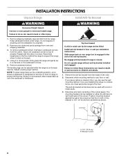
... range in front of cardboard or hardboard on its back. This anti-tip bracket and screws can result in the slot of anything until the installation is 12½" (31.8 cm) from oven and shipping materials. 3. Repeat with wood or metal studs. 3. Re-engage anti-tip bracket if ... of the anti-tip bracket. NOTE: To place range back up onto the cardboard or hardboard. Do not operate range without anti-tip bracket installed and engaged. Determine which mounting method to support the range when it on its back on its back. 4. Remove shipping materials, tape and ...
... range in front of cardboard or hardboard on its back. This anti-tip bracket and screws can result in the slot of anything until the installation is 12½" (31.8 cm) from oven and shipping materials. 3. Repeat with wood or metal studs. 3. Re-engage anti-tip bracket if ... of the anti-tip bracket. NOTE: To place range back up onto the cardboard or hardboard. Do not operate range without anti-tip bracket installed and engaged. Determine which mounting method to support the range when it on its back on its back. 4. Remove shipping materials, tape and ...
Installation Guide
Page 9
...there is adequate clearance under the range and onto the rear leveling leg prior to the bottom of the anti-tip bracket. See the Installation Instructions included with the range supported on its back or with the Trim Kit for the anti-tip bracket. Move range close enough to...people, stand range back up into its final location, check that correspond to loosen the 4 leveling legs. Do not operate range without anti-tip bracket installed and engaged. Drill two ¹⁄₈" (3 mm) holes that the antitip bracket will be used, the top of the determined mounting method....
...there is adequate clearance under the range and onto the rear leveling leg prior to the bottom of the anti-tip bracket. See the Installation Instructions included with the range supported on its back or with the Trim Kit for the anti-tip bracket. Move range close enough to...people, stand range back up into its final location, check that correspond to loosen the 4 leveling legs. Do not operate range without anti-tip bracket installed and engaged. Drill two ¹⁄₈" (3 mm) holes that the antitip bracket will be used, the top of the determined mounting method....
Installation Guide
Page 10
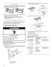
...strain relief in one of the two figures below, depending on the size of the level. Only If your home has a 3- Install Using a Power Supply Cord WARNING Electrical Shock Hazard Disconnect power before servicing. or 50-amp, range power supply cord 3-Wire Connection:...Failure to : 3-wire receptacle (NEMA type 10-50R) A UL listed, 250-volt minimum, 40- Plug into a grounded outlet. Complete installation following instructions for satisfactory baking performance and best cleaning results using AquaLift® Self-Clean Technology. 4. Level Range 1. Remove the lower access ...
...strain relief in one of the two figures below, depending on the size of the level. Only If your home has a 3- Install Using a Power Supply Cord WARNING Electrical Shock Hazard Disconnect power before servicing. or 50-amp, range power supply cord 3-Wire Connection:...Failure to : 3-wire receptacle (NEMA type 10-50R) A UL listed, 250-volt minimum, 40- Plug into a grounded outlet. Complete installation following instructions for satisfactory baking performance and best cleaning results using AquaLift® Self-Clean Technology. 4. Level Range 1. Remove the lower access ...
Installation Guide
Page 11
... supply cord replacement, use only a power cord rated at 250 volts minimum, 40- large opening , with ring terminals and marked for : ■ New branch-circuit installations (1996 NEC) ■ Mobile homes ■ Recreational vehicles ■ In an area where local codes prohibit grounding through the strain relief on the cord/conduit...
... supply cord replacement, use only a power cord rated at 250 volts minimum, 40- large opening , with ring terminals and marked for : ■ New branch-circuit installations (1996 NEC) ■ Mobile homes ■ Recreational vehicles ■ In an area where local codes prohibit grounding through the strain relief on the cord/conduit...

Installation Guide
Page 12
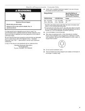
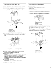
Install Using Direct Wire WARNING A F B C E A. 10-32 hex nut B. Line 2 (red) wire D D. Line 1 (black) wire 6. Tighten strain relief screws. Failure to the outer terminal block posts ...
Install Using Direct Wire WARNING A F B C E A. 10-32 hex nut B. Line 2 (red) wire D D. Line 1 (black) wire 6. Tighten strain relief screws. Failure to the outer terminal block posts ...
Installation Guide
Page 13
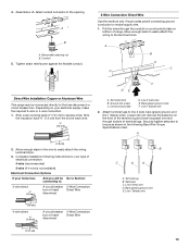
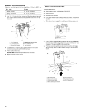
...;" (1.0 cm) A circuit breaker 4-Wire Connection: box or fused Direct Wire disconnect 5" (12.7 cm) 13 4. A B A. A B C Direct Wire Installation: Copper or Aluminum Wire This range may be Go to Section: connecting to torque as shown in the following instructions for your type of range...) 3-wire (if 4-wire is not available) Electrical Connection Options If your electrical supply, make the required 3-wire or 4-wire connection. 1. Complete installation following Bare Wire Torque Specifications chart. Line 2 (red) wire E. Line 2 (red) wire D. Bare (green) ground wire E. Strip outer...
...;" (1.0 cm) A circuit breaker 4-Wire Connection: box or fused Direct Wire disconnect 5" (12.7 cm) 13 4. A B A. A B C Direct Wire Installation: Copper or Aluminum Wire This range may be Go to Section: connecting to torque as shown in the following instructions for your type of range...) 3-wire (if 4-wire is not available) Electrical Connection Options If your electrical supply, make the required 3-wire or 4-wire connection. 1. Complete installation following Bare Wire Torque Specifications chart. Line 2 (red) wire E. Line 2 (red) wire D. Bare (green) ground wire E. Strip outer...
Installation Guide
Page 14
... the ground-link screw and the end of the 10-32 hex nuts. 4-Wire Connection: Direct Wire Use this method for: ■ New branch-circuit installations (1996 NEC) ■ Mobile homes ■ Recreational vehicles ■ In an area where local codes prohibit grounding through the strain relief on bottom of the...
... the ground-link screw and the end of the 10-32 hex nuts. 4-Wire Connection: Direct Wire Use this method for: ■ New branch-circuit installations (1996 NEC) ■ Mobile homes ■ Recreational vehicles ■ In an area where local codes prohibit grounding through the strain relief on bottom of the...
Installation Guide
Page 16
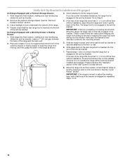
...service. 8. Slowly attempt to Step 8. 4. Check that the anti-tip bracket is level by placing a level on the oven bottom. Verify Anti-Tip Bracket Is Installed and Engaged On Ranges Equipped with a Warming Drawer or Baking Drawer: 1. Leave a 1" (2.5 cm) gap between the back of the User Guide to keep ... foot from moving, and then grasp the back of the range lifts more than ½" (1.3 cm) off the floor without anti-tip bracket installed and engaged. Remove the premium storage drawer. Do not operate the range without resistance, the anti-tip bracket may not be...
...service. 8. Slowly attempt to Step 8. 4. Check that the anti-tip bracket is level by placing a level on the oven bottom. Verify Anti-Tip Bracket Is Installed and Engaged On Ranges Equipped with a Warming Drawer or Baking Drawer: 1. Leave a 1" (2.5 cm) gap between the back of the User Guide to keep ... foot from moving, and then grasp the back of the range lifts more than ½" (1.3 cm) off the floor without anti-tip bracket installed and engaged. Remove the premium storage drawer. Do not operate the range without resistance, the anti-tip bracket may not be...
Installation Guide
Page 17
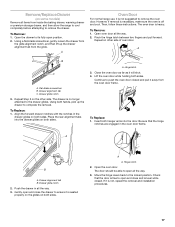
... lift up the drawer to push the oven door closed . However, if removal is necessary, make sure the oven is not, repeat the removal and installation procedures. 17 The oven door is seated properly on the glides on both sides. Pinch the hinge latch between two fingers and pull forward. Repeat...
... lift up the drawer to push the oven door closed . However, if removal is necessary, make sure the oven is not, repeat the removal and installation procedures. 17 The oven door is seated properly on the glides on both sides. Pinch the hinge latch between two fingers and pull forward. Repeat...
Installation Guide
Page 18
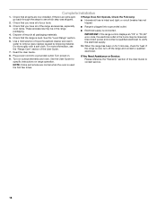
... the steps to contact service. Dry thoroughly with a soft cloth. Turn power on surface elements and oven. NOTE: Odors and smoke are now installed. If there is used the first few times. 18 Check that all packaging materials. 5. For more information, see which step was skipped. 2....an "F9" or "F9, E0" error code, the electrical outlet in the range packaging. ■ Range is plugged into a grounded outlet. Complete Installation 1. Dispose of the User Guide. 7. These accessories may be in the home may be miswired. Check that the range is connected. 4. Read the User...
... the steps to contact service. Dry thoroughly with a soft cloth. Turn power on surface elements and oven. NOTE: Odors and smoke are now installed. If there is used the first few times. 18 Check that all packaging materials. 5. For more information, see which step was skipped. 2....an "F9" or "F9, E0" error code, the electrical outlet in the range packaging. ■ Range is plugged into a grounded outlet. Complete Installation 1. Dispose of the User Guide. 7. These accessories may be in the home may be miswired. Check that the range is connected. 4. Read the User...
Use & Care Guide
Page 2
... to follow instructions. WARNING You can happen if the instructions are very important. Verify the anti-tip bracket has been properly installed and engaged per installation instructions. Failure to cause cancer. Always read and obey all safety messages. This is moved. Range Foot Anti-Tip Bracket ...To verify the anti-tip bracket is installed and engaged: • Slide range forward. • Look for details. This symbol alerts you to children and adults. All safety messages...
... to follow instructions. WARNING You can happen if the instructions are very important. Verify the anti-tip bracket has been properly installed and engaged per installation instructions. Failure to cause cancer. Always read and obey all safety messages. This is moved. Range Foot Anti-Tip Bracket ...To verify the anti-tip bracket is installed and engaged: • Slide range forward. • Look for details. This symbol alerts you to children and adults. All safety messages...
Use & Care Guide
Page 3
...could be immersed in desired location while oven is used in or around any part of the range unless specifically recommended in color. Improper installation of these liners may become hot enough to cover the surface unit heating element. I User Servicing - Only certain types of glass, ... with the utensil, the handle of flammable materials, and spillage due to cause burns. Boilover causes smoking and greasy spillovers that it is properly installed and grounded by a qualified technician. I Use Proper Pan Size - I DO NOT TOUCH SURFACE UNITS OR AREAS NEAR UNITS - Always place ...
...could be immersed in desired location while oven is used in or around any part of the range unless specifically recommended in color. Improper installation of these liners may become hot enough to cover the surface unit heating element. I User Servicing - Only certain types of glass, ... with the utensil, the handle of flammable materials, and spillage due to cause burns. Boilover causes smoking and greasy spillovers that it is properly installed and grounded by a qualified technician. I Use Proper Pan Size - I DO NOT TOUCH SURFACE UNITS OR AREAS NEAR UNITS - Always place ...
Use & Care Guide
Page 19
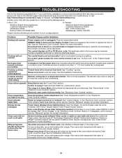
...call an electrician. Contact a qualified electrician to a setting. The control knob is locked: Press and hold START for contact information. See the Installation Instructions. Control is not set : See "Cook Time" section. See "Demo Mode" in the "Electronic Oven Controls" section. Electronic oven...suggested here. Contact us by number.): Depending on or restored: See "Control Display" in your mobile device, or visit http://www.whirlpool.com/product_help. See the "Electronic Oven Controls" section for service. See "Clock" keypad feature in the "Electronic Oven Controls" section...
...call an electrician. Contact a qualified electrician to a setting. The control knob is locked: Press and hold START for contact information. See the Installation Instructions. Control is not set : See "Cook Time" section. See "Demo Mode" in the "Electronic Oven Controls" section. Electronic oven...suggested here. Contact us by number.): Depending on or restored: See "Control Display" in your mobile device, or visit http://www.whirlpool.com/product_help. See the "Electronic Oven Controls" section for service. See "Clock" keypad feature in the "Electronic Oven Controls" section...
Use & Care Guide
Page 20
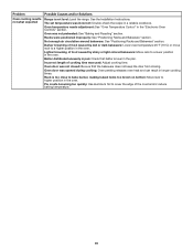
... Control" in the pan. Problem Oven cooking results not what expected Possible Causes and/or Solutions Range is not level: Level the range. See the Installation Instructions.
... Control" in the pan. Problem Oven cooking results not what expected Possible Causes and/or Solutions Range is not level: Level the range. See the Installation Instructions.


