Installation Guide
Page 1
... Anti-Tip Bracket 6 Adjust Leveling Legs 7 Level Range 8 Electrical Connection - Only 8 Verify Anti-Tip Bracket Is Installed and Engaged 14 Remove/Replace Drawer 15 Oven Door 15 Complete Installation 16 IMPORTANT: ...Save for local electrical inspector's use. U.S.A. IMPORTANT : ÀW1co0n8s4e2r0v1e0rApour consultation par l'inspecteur local des installations électriques. INSTALLATION INSTRUCTIONS FRONT CONTROL ELECTRIC RANGES Table of Contents RANGE SAFETY 2 INSTALLATION REQUIREMENTS 3 Tools and Parts 3 Location Requirements 3 Electrical Requirements -
... Anti-Tip Bracket 6 Adjust Leveling Legs 7 Level Range 8 Electrical Connection - Only 8 Verify Anti-Tip Bracket Is Installed and Engaged 14 Remove/Replace Drawer 15 Oven Door 15 Complete Installation 16 IMPORTANT: ...Save for local electrical inspector's use. U.S.A. IMPORTANT : ÀW1co0n8s4e2r0v1e0rApour consultation par l'inspecteur local des installations électriques. INSTALLATION INSTRUCTIONS FRONT CONTROL ELECTRIC RANGES Table of Contents RANGE SAFETY 2 INSTALLATION REQUIREMENTS 3 Tools and Parts 3 Location Requirements 3 Electrical Requirements -
Installation Guide
Page 2
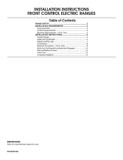
...be killed or seriously injured if you don't follow instructions. Do not operate range without anti-tip bracket installed and engaged. Always read and obey all safety messages. Slide range back so rear range foot is moved. RANGE SAFETY Your safety and the safety of injury, and tell you what the... is , tell you and others are not followed. Install anti-tip bracket to floor or wall. • Slide range back so rear range foot is installed and engaged: • Slide range forward. • Look for details. 2 All safety messages will tell you what can kill or hurt you how to...
...be killed or seriously injured if you don't follow instructions. Do not operate range without anti-tip bracket installed and engaged. Always read and obey all safety messages. Slide range back so rear range foot is moved. RANGE SAFETY Your safety and the safety of injury, and tell you what the... is , tell you and others are not followed. Install anti-tip bracket to floor or wall. • Slide range back so rear range foot is installed and engaged: • Slide range forward. • Look for details. 2 All safety messages will tell you what can kill or hurt you how to...
Installation Guide
Page 3
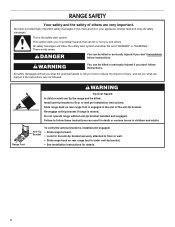
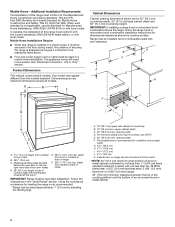
... Location Requirements IMPORTANT: Observe all parts are shown must end in accordance with the requirements of UL and CSA International and complies with ranges. Thickness of the cabinets. ■■ All openings in the kitchen. ■■ Recessed installations must be located for use ...be rated at least 200°F (93°C). ■■ Use an insulated pad or ¼" (0.64 cm) plywood under range if installing range over the heated surface units, cabinet storage space located above the surface units should be installed. Check existing electrical supply. The model/...
... Location Requirements IMPORTANT: Observe all parts are shown must end in accordance with the requirements of UL and CSA International and complies with ranges. Thickness of the cabinets. ■■ All openings in the kitchen. ■■ Recessed installations must be located for use ...be rated at least 200°F (93°C). ■■ Use an insulated pad or ¼" (0.64 cm) plywood under range if installing range over the heated surface units, cabinet storage space located above the surface units should be installed. Check existing electrical supply. The model/...
Installation Guide
Page 4
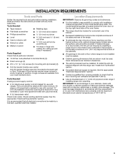
... not extend into the cutout. * NOTE: 24" (61.0 cm) minimum when bottom of wood or metal cabinet is installed in the "Level Range" section. Range may appear different from front of console to combustible walls with not less than No. 28 MSG sheet steel, 0.015" (0.4 mm) stainless steel,... 0.024" (0.6 mm) aluminum or 0.020" (0.5 mm) copper. 30" (76.2 cm) minimum clearance between the top of the cooking platform and the bottom of range F. 291⁄64" (73.7 cm) max. G. 13¹⁄8" (33.3 cm) H. 7¹¹⁄16" (19.5 cm) I E F A. 1³⁄16" (3.0 ...
... not extend into the cutout. * NOTE: 24" (61.0 cm) minimum when bottom of wood or metal cabinet is installed in the "Level Range" section. Range may appear different from front of console to combustible walls with not less than No. 28 MSG sheet steel, 0.015" (0.4 mm) stainless steel,... 0.024" (0.6 mm) aluminum or 0.020" (0.5 mm) copper. 30" (76.2 cm) minimum clearance between the top of the cooking platform and the bottom of range F. 291⁄64" (73.7 cm) max. G. 13¹⁄8" (33.3 cm) H. 7¹¹⁄16" (19.5 cm) I E F A. 1³⁄16" (3.0 ...
Installation Guide
Page 5
... the appliance is properly grounded. U.S.A. U.S.A. Only" section. ■■ Allow at least 6 ft (1.8 m) of the oven frame. ■■ This range is manufactured with a nominal 1³⁄8" (3.5 cm) diameter connection opening. ■■ A circuit breaker is ever necessary. ■■ A UL listed... be Type SRD or SRDT with a UL listed strain relief and be using and follow the instructions provided for use with ranges. If it is recommended that a qualified electrical installer determine that specify use a 50-amp rated cord with upturned ends, terminating...
... the appliance is properly grounded. U.S.A. U.S.A. Only" section. ■■ Allow at least 6 ft (1.8 m) of the oven frame. ■■ This range is manufactured with a nominal 1³⁄8" (3.5 cm) diameter connection opening. ■■ A circuit breaker is ever necessary. ■■ A UL listed... be Type SRD or SRDT with a UL listed strain relief and be using and follow the instructions provided for use with ranges. If it is recommended that a qualified electrical installer determine that specify use a 50-amp rated cord with upturned ends, terminating...

Installation Guide
Page 6
... Bracket WARNING 1. Remove oven racks and parts package from centerline as shown. See the "Adjust Leveling Legs" section. Using 2 or more people, stand range back up into a standing position, put a sheet of cardboard or hardboard on the floor in front of the cutout space. Bracket V-notch 6 INSTALLATION ...on its back. 4. Stack one cardboard corner on top of the cutout. If you have a stone or masonry floor, you must secure the range to do so can be killed. The mounting bracket can result in the slot of anything until the installation is complete. 2. Do not dispose...
... Bracket WARNING 1. Remove oven racks and parts package from centerline as shown. See the "Adjust Leveling Legs" section. Using 2 or more people, stand range back up into a standing position, put a sheet of cardboard or hardboard on the floor in front of the cutout space. Bracket V-notch 6 INSTALLATION ...on its back. 4. Stack one cardboard corner on top of the cutout. If you have a stone or masonry floor, you must secure the range to do so can be killed. The mounting bracket can result in the slot of anything until the installation is complete. 2. Do not dispose...
Installation Guide
Page 7
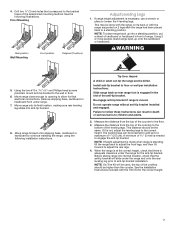
... method. Measure the distance from the top of the cooktop to continue installing the range, using the following illustrations. NOTE: If a Trim Kit will slide under range. 7. If range height adjustment is standing, tilt the range back to adjust the front legs, and then tilt forward to the floor. 3....Drill two ¹⁄8" (3 mm) holes that the antitip bracket will be used, the top of 1" (2.5 cm). Using 2 or more people, stand range back up to children and adults. 2. Tip Over Hazard A child or adult can result in death or serious burns to a maximum of the cooktop should...
... method. Measure the distance from the top of the cooktop to continue installing the range, using the following illustrations. NOTE: If a Trim Kit will slide under range. 7. If range height adjustment is standing, tilt the range back to adjust the front legs, and then tilt forward to the floor. 3....Drill two ¹⁄8" (3 mm) holes that the antitip bracket will be used, the top of 1" (2.5 cm). Using 2 or more people, stand range back up to children and adults. 2. Tip Over Hazard A child or adult can result in death or serious burns to a maximum of the cooktop should...
Installation Guide
Page 8
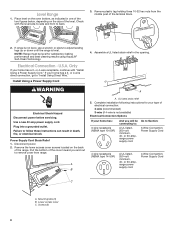
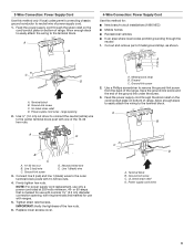
... Use a new 40 amp power supply cord. A B A. UL listed strain relief 5. Remove plastic tag holding three 10-32 hex nuts from range. U.S.A. or 4-wire receptacle, continue with the level side-to-side and front to follow these instructions can result in death, fire, or electrical shock...Section: 3-Wire Connection: Power Supply Cord 4-wire receptacle (NEMA type 14-50R) A UL listed, 250-volt minimum, 40- or 50-amp, range power supply cord 4-Wire Connection: Power Supply Cord C A. Electrical Connection - Remove the lower access cover screws located on the oven bottom, as indicated...
... Use a new 40 amp power supply cord. A B A. UL listed strain relief 5. Remove plastic tag holding three 10-32 hex nuts from range. U.S.A. or 4-wire receptacle, continue with the level side-to-side and front to follow these instructions can result in death, fire, or electrical shock...Section: 3-Wire Connection: Power Supply Cord 4-wire receptacle (NEMA type 14-50R) A UL listed, 250-volt minimum, 40- or 50-amp, range power supply cord 4-Wire Connection: Power Supply Cord C A. Electrical Connection - Remove the lower access cover screws located on the oven bottom, as indicated...
Installation Guide
Page 9
...power supply cord through the neutral 1. Allow enough slack to easily attach the wiring to remove the ground-link screw from the back of the range. Tighten strain relief screws. Replace lower access cover. A B 4-Wire Connection: Power Supply Cord Use this method only if local codes permit ...a power cord rated at 250 volts minimum, 40- Feed the power supply cord through the strain relief on the cord/conduit plate on bottom of range. Terminal block B. 3-Wire Connection: Power Supply Cord Use this method for: ■■ New branch-circuit installations (1996 NEC) ■■ ...
...power supply cord through the neutral 1. Allow enough slack to easily attach the wiring to remove the ground-link screw from the back of the range. Tighten strain relief screws. Replace lower access cover. A B 4-Wire Connection: Power Supply Cord Use this method only if local codes permit ...a power cord rated at 250 volts minimum, 40- Feed the power supply cord through the strain relief on the cord/conduit plate on bottom of range. Terminal block B. 3-Wire Connection: Power Supply Cord Use this method for: ■■ New branch-circuit installations (1996 NEC) ■■ ...

Installation Guide
Page 10
... 10-32 hex nuts from the middle post of the cover toward you and out to remove cover from the power supply cord to the range with the groundlink screw and ground-link section. A B C A. Ground-link screw C. or 50-amps that is marked for use with nominal 1³⁄... over the ground-link section. 5. Use ³⁄8" (1.0 cm) nut driver to connect the neutral (white) wire to connect the green ground wire from range. Lower access cover C. IMPORTANT: Verify the tightness of the 10-32 hex nuts. Replace lower access cover. Line 1 (black) wire 6. Disconnect power. 2....
... 10-32 hex nuts from the middle post of the cover toward you and out to remove cover from the power supply cord to the range with the groundlink screw and ground-link section. A B C A. Ground-link screw C. or 50-amps that is marked for use with nominal 1³⁄... over the ground-link section. 5. Use ³⁄8" (1.0 cm) nut driver to connect the neutral (white) wire to connect the green ground wire from range. Lower access cover C. IMPORTANT: Verify the tightness of the 10-32 hex nuts. Replace lower access cover. Line 1 (black) wire 6. Disconnect power. 2....

Installation Guide
Page 11
...Line 1 (black) wire 5" (12.7 cm) 11 Allow enough slack to easily attach the wiring to easily attach the wiring terminal block. 3. Depending on bottom of range. Attach terminal lugs to expose wires. Securely tighten setscrew to Section: 3-Wire Connection: Direct Wire 3" (7.6 cm) 4-wire direct ³⁄₈" (1.0 cm) ...cm) 3" (7.6 cm) 2. Loosen (do not remove) the setscrew on the front of terminal lugs. A B C Direct Wire Installation: Copper or Aluminum Wire This range may be connecting to: A circuit breaker box or fused disconnect Go to torque as shown in the opening.
...Line 1 (black) wire 5" (12.7 cm) 11 Allow enough slack to easily attach the wiring to easily attach the wiring terminal block. 3. Depending on bottom of range. Attach terminal lugs to expose wires. Securely tighten setscrew to Section: 3-Wire Connection: Direct Wire 3" (7.6 cm) 4-wire direct ³⁄₈" (1.0 cm) ...cm) 3" (7.6 cm) 2. Loosen (do not remove) the setscrew on the front of terminal lugs. A B C Direct Wire Installation: Copper or Aluminum Wire This range may be connecting to: A circuit breaker box or fused disconnect Go to torque as shown in the opening.

Installation Guide
Page 12
...Line 2 (red) wire C. Bare (green) ground wire E. Connect line 2 (red) and line 1 (black) wires to remove the ground-link screw from the back of the range. Firmly tighten hex nuts. IMPORTANT: Verify the tightness of metal ground strap, as shown. Ground-link screw 2. F A E B D C A. 10-32 hex nut B. Metal... (1.0 cm) nut driver to connect the bare (green) ground wire to the terminal block. Save the ground-link screw and the end of range. Neutral (white) wire G. Line 1 (black) wire 12 Terminal lug 4. Allow enough slack to easily attach wiring to the center terminal block ...
...Line 2 (red) wire C. Bare (green) ground wire E. Connect line 2 (red) and line 1 (black) wires to remove the ground-link screw from the back of the range. Firmly tighten hex nuts. IMPORTANT: Verify the tightness of metal ground strap, as shown. Ground-link screw 2. F A E B D C A. 10-32 hex nut B. Metal... (1.0 cm) nut driver to connect the bare (green) ground wire to the terminal block. Save the ground-link screw and the end of range. Neutral (white) wire G. Line 1 (black) wire 12 Terminal lug 4. Allow enough slack to easily attach wiring to the center terminal block ...

Installation Guide
Page 13
... nut B. A 5. IMPORTANT: Verify the tightness of the hex nuts. 9. Bare (green) ground wire D. Terminal lug B. Replace lower access cover. 13 Attach terminal lugs to the range with 10-32 hex nuts. 8. 4. Setscrew C. Terminal lug 7. Securely tighten setscrew to the terminal block - 20 lbs-in. (2.3 N-m) Wire Awg 8 gauge copper 6 gauge aluminum Torque...
... nut B. A 5. IMPORTANT: Verify the tightness of the hex nuts. 9. Bare (green) ground wire D. Terminal lug B. Replace lower access cover. 13 Attach terminal lugs to the range with 10-32 hex nuts. 8. 4. Setscrew C. Terminal lug 7. Securely tighten setscrew to the terminal block - 20 lbs-in. (2.3 N-m) Wire Awg 8 gauge copper 6 gauge aluminum Torque...

Installation Guide
Page 14
...drawer to ensure that the anti-tip bracket is engaged in the anti-tip bracket. If the rear of the anti-tip bracket. Move the range into anti-tip bracket. Leave a 1" (2.5 cm) gap between the back of the anti-tip bracket. 7. Repeat steps 1 and 2 to keep the...(1.3 cm) off the floor without anti-tip bracket installed and engaged. Check that the rear range foot is a snapping or popping sound when lifting the range, the range may not be fully engaged in the anti-tip bracket. Slide range into final location, making sure rear leveling leg slides into the slot of the...
...drawer to ensure that the anti-tip bracket is engaged in the anti-tip bracket. If the rear of the anti-tip bracket. Move the range into anti-tip bracket. Leave a 1" (2.5 cm) gap between the back of the anti-tip bracket. 7. Repeat steps 1 and 2 to keep the...(1.3 cm) off the floor without anti-tip bracket installed and engaged. Check that the rear range foot is a snapping or popping sound when lifting the range, the range may not be fully engaged in the anti-tip bracket. Slide range into final location, making sure rear leveling leg slides into the slot of the...

Installation Guide
Page 15
... to push the oven door closed . If it away from inside the baking drawer, warming drawer or premium storage drawer, and then allow the range to cool completely before attempting to remove the oven door. Raise the front edge, and then lift out. However, if removal is necessary, make... to open and close and is seated properly on the rails on both sides. Remove/Replace Drawer Remove all the way. 3. Oven Door For normal range use, it will shut. 4. A A. Hinge notch 2. A A. The oven door is not suggested to remove the drawer. Place the rear alignment tabs into the door...
... to push the oven door closed . If it away from inside the baking drawer, warming drawer or premium storage drawer, and then allow the range to cool completely before attempting to remove the oven door. Raise the front edge, and then lift out. However, if removal is necessary, make... to open and close and is seated properly on the rails on both sides. Remove/Replace Drawer Remove all the way. 3. Oven Door For normal range use, it will shut. 4. A A. Hinge notch 2. A A. The oven door is not suggested to remove the drawer. Place the rear alignment tabs into the door...
Installation Guide
Page 16
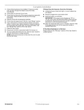
... all of the User Guide to remove waxy residue caused by shipping material. See the "Level Range" section. 6. Use a mild solution of your tools. 3. Read the User Guide. 8. If the range is intact and tight; Check that you have all packaging materials. 5. NOTE: Odors and smoke... an extra part, go back through the steps to verify the electrical supply. 10. Turn on range operation. If You Need Assistance or Service: Please reference the "Warranty" section of the range accessories, especially oven racks. Dispose of the User Guide. 7. For more information, see which step...
... all of the User Guide to remove waxy residue caused by shipping material. See the "Level Range" section. 6. Use a mild solution of your tools. 3. Read the User Guide. 8. If the range is intact and tight; Check that you have all packaging materials. 5. NOTE: Odors and smoke... an extra part, go back through the steps to verify the electrical supply. 10. Turn on range operation. If You Need Assistance or Service: Please reference the "Warranty" section of the range accessories, especially oven racks. Dispose of the User Guide. 7. For more information, see which step...
Dimension Guide
Page 1
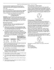
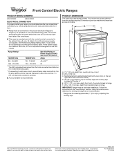
...behind the oven door on the model/serial/rating plate. See the following Range Rating chart. Front Control Electric Ranges PRODUCT MODEL NUMBERS WEC310S0F WEE510S0F ELECTRICAL CONNECTION To properly install your range, you must determine the type of electrical connection you will be using and...the cabinet. Your model may appear different from cooktop to back of range IMPORTANT: Range must be connected to a 50-amp circuit, use a 4-wire power supply cord rated at 250 volts, 40- Because Whirlpool Corporation includes a continuous commitment to improve our products, we reserve the...
...behind the oven door on the model/serial/rating plate. See the following Range Rating chart. Front Control Electric Ranges PRODUCT MODEL NUMBERS WEC310S0F WEE510S0F ELECTRICAL CONNECTION To properly install your range, you must determine the type of electrical connection you will be using and...the cabinet. Your model may appear different from cooktop to back of range IMPORTANT: Range must be connected to a 50-amp circuit, use a 4-wire power supply cord rated at 250 volts, 40- Because Whirlpool Corporation includes a continuous commitment to improve our products, we reserve the...
Dimension Guide
Page 2
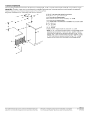
G. 131/8" (33.3 cm) H. 711/16" (19.5 cm) A E I Because Whirlpool Corporation includes a continuous commitment to improve our products, we reserve the right to change materials and specifications without notice. H I F J I . 413/16" (12.2 cm) J. 311/16" (9.4... combination installation instructions for 25" (64.0 cm) countertop depth, 24" (61.0 cm) base cabinet depth and 36" (91.4 cm) countertop height. W10842010A 07/14/2016 Range may be installed next to top of 2 Ref. A. 18" (45.7 cm) upper side cabinet to countertop B D B. 13" (33 cm) max. For complete details, see ...
G. 131/8" (33.3 cm) H. 711/16" (19.5 cm) A E I Because Whirlpool Corporation includes a continuous commitment to improve our products, we reserve the right to change materials and specifications without notice. H I F J I . 413/16" (12.2 cm) J. 311/16" (9.4... combination installation instructions for 25" (64.0 cm) countertop depth, 24" (61.0 cm) base cabinet depth and 36" (91.4 cm) countertop height. W10842010A 07/14/2016 Range may be installed next to top of 2 Ref. A. 18" (45.7 cm) upper side cabinet to countertop B D B. 13" (33 cm) max. For complete details, see ...

Use & Care Guide
Page 1
...Warm 10 Aluminum Foil 11 Positioning Racks and Bakeware 11 Oven Vent 11 Baking and Roasting 11 Broiling 12 Cook Time 12 RANGE CARE 13 Self-Cleaning Cycle 13 General Cleaning 14 Oven Light 15 TROUBLESHOOTING 16 ACCESSORIES 18 WARRANTY 19 W10887091B UUSSEEEELLRREECCIINNTTSSRRTTIICCRRUURRCCAATTNNIIGGOOEENNSS THANK YOU...derecho del marco frontal del horno. Model Number Serial Number Para una versión de estas instrucciones en español, visite www.whirlpool.com. Table of the front frame. Para referencia futura, tome nota de los números de modelo y de serie de su ...
...Warm 10 Aluminum Foil 11 Positioning Racks and Bakeware 11 Oven Vent 11 Baking and Roasting 11 Broiling 12 Cook Time 12 RANGE CARE 13 Self-Cleaning Cycle 13 General Cleaning 14 Oven Light 15 TROUBLESHOOTING 16 ACCESSORIES 18 WARRANTY 19 W10887091B UUSSEEEELLRREECCIINNTTSSRRTTIICCRRUURRCCAATTNNIIGGOOEENNSS THANK YOU...derecho del marco frontal del horno. Model Number Serial Number Para una versión de estas instrucciones en español, visite www.whirlpool.com. Table of the front frame. Para referencia futura, tome nota de los números de modelo y de serie de su ...

Use & Care Guide
Page 2
... on your appliance. WARNING You can tip if you don't follow the safety alert symbol and either the word "DANGER" or "WARNING." However, the range can be killed or seriously injured if you apply too much force or weight to cause cancer. Re-engage anti-tip bracket if... range is the safety alert symbol. Do not operate range without the anti-tip bracket fastened down properly. This symbol alerts you how to cause birth defects or other reproductive ...
... on your appliance. WARNING You can tip if you don't follow the safety alert symbol and either the word "DANGER" or "WARNING." However, the range can be killed or seriously injured if you apply too much force or weight to cause cancer. Re-engage anti-tip bracket if... range is the safety alert symbol. Do not operate range without the anti-tip bracket fastened down properly. This symbol alerts you how to cause birth defects or other reproductive ...


