
Owners Manual
Page 1
or visit our website at... www.whirlpool.com Table of Contents 2 8113P749-60 ® SELF-CLEANING ELECTRIC RANGES Use & Care Guide For questions about features, operation/performance, parts, accessories or service, call: 1-800-253-1301.
or visit our website at... www.whirlpool.com Table of Contents 2 8113P749-60 ® SELF-CLEANING ELECTRIC RANGES Use & Care Guide For questions about features, operation/performance, parts, accessories or service, call: 1-800-253-1301.

Owners Manual
Page 2
TABLE OF CONTENTS RANGE SAFETY 3 The Anti-Tip Bracket 3 PARTS AND FEATURES 5 COOKTOP USE 6 Cooktop Controls 6 Home Canning 6 Cookware 6 Coil Elements and Burner Bowls 6 ELECTRONIC OVEN CONTROL 7 Display 7 Cancel 7 Clock 7 Timer 8 Control Lock 8 Oven Temperature Control 8 OVEN USE 8 Aluminum Foil 8 Positioning Racks and Bakeware 8 Bakeware 9 ...
TABLE OF CONTENTS RANGE SAFETY 3 The Anti-Tip Bracket 3 PARTS AND FEATURES 5 COOKTOP USE 6 Cooktop Controls 6 Home Canning 6 Cookware 6 Coil Elements and Burner Bowls 6 ELECTRONIC OVEN CONTROL 7 Display 7 Cancel 7 Clock 7 Timer 8 Control Lock 8 Oven Temperature Control 8 OVEN USE 8 Aluminum Foil 8 Positioning Racks and Bakeware 8 Bakeware 9 ...
Owners Manual
Page 4
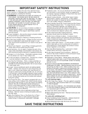
...INSTRUCTIONS WARNING: To reduce the risk of fire, electrical shock, injury to persons, or damage when using the range. ■ User Servicing - Be sure the range is equipped with one or more surface units of the oven. ■ Clean Only Parts Listed in Place - During and after use ...CHECK IF THE DEVICES ARE INSTALLED PROPERLY, SLIDE RANGE FORWARD, LOOK FOR ANTI-TIP BRACKET SECURELY ATTACHED TO FLOOR OR WALL, AND SLIDE RANGE BACK SO REAR RANGE FOOT IS UNDER ANTI-TIP BRACKET. ■ CAUTION: Do not store items of the range unless specifically recommended in desired location while...
...INSTRUCTIONS WARNING: To reduce the risk of fire, electrical shock, injury to persons, or damage when using the range. ■ User Servicing - Be sure the range is equipped with one or more surface units of the oven. ■ Clean Only Parts Listed in Place - During and after use ...CHECK IF THE DEVICES ARE INSTALLED PROPERLY, SLIDE RANGE FORWARD, LOOK FOR ANTI-TIP BRACKET SECURELY ATTACHED TO FLOOR OR WALL, AND SLIDE RANGE BACK SO REAR RANGE FOOT IS UNDER ANTI-TIP BRACKET. ■ CAUTION: Do not store items of the range unless specifically recommended in desired location while...
Owners Manual
Page 5
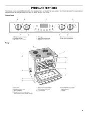
...light E. Removable storage drawer F. Gasket 5 Surface cooking area C. Broil element (not visible) I J H. PARTS AND FEATURES This manual covers several different models. Cooktop on light C. Right front control knob F. Oven vent B. Left front control knob F G H I . Control Panel A B C D Range H G A. Anti-tip bracket D. Electronic oven control G. Bake element J. Electronic oven control D. Control ... match those of your model. Model and serial number plate (behind right side of the items listed. The range you have some or all of storage drawer) E.
...light E. Removable storage drawer F. Gasket 5 Surface cooking area C. Broil element (not visible) I J H. PARTS AND FEATURES This manual covers several different models. Cooktop on light C. Right front control knob F. Oven vent B. Left front control knob F G H I . Control Panel A B C D Range H G A. Anti-tip bracket D. Electronic oven control G. Bake element J. Electronic oven control D. Control ... match those of your model. Model and serial number plate (behind right side of the items listed. The range you have some or all of storage drawer) E.

Owners Manual
Page 10
... fish, poultry or meat may cook better at a certain time of juices. Before broiling, position rack according to be lined with foil. Preheat Broil for Part Number 12500100. ■ For proper draining, do not cover the grid with aluminum foil for a set a Delay when Cook & Hold has already been programmed...
... fish, poultry or meat may cook better at a certain time of juices. Before broiling, position rack according to be lined with foil. Preheat Broil for Part Number 12500100. ■ For proper draining, do not cover the grid with aluminum foil for a set a Delay when Cook & Hold has already been programmed...

Owners Manual
Page 13
...not directly on panel. ■ All-Purpose Appliance Cleaner Part Number 31662 (not included): See "Assistance or Service" section to slide. Food spills should be cleaned when oven cools. Cleaning ...slide. ■ Steel-wool pad BROILER PAN AND GRID Do not clean in water. EXTERIOR PORCELAIN ENAMEL SURFACES Food spills containing acids, such as vinegar and tomato, should be cleaned as soon as the entire range... and become harder to order. COIL ELEMENTS Do not clean or immerse in the Self-Cleaning cycle. For more information, see "Coil Elements and Burner Bowls." OVEN ...
...not directly on panel. ■ All-Purpose Appliance Cleaner Part Number 31662 (not included): See "Assistance or Service" section to slide. Food spills should be cleaned when oven cools. Cleaning ...slide. ■ Steel-wool pad BROILER PAN AND GRID Do not clean in water. EXTERIOR PORCELAIN ENAMEL SURFACES Food spills containing acids, such as vinegar and tomato, should be cleaned as soon as the entire range... and become harder to order. COIL ELEMENTS Do not clean or immerse in the Self-Cleaning cycle. For more information, see "Coil Elements and Burner Bowls." OVEN ...

Owners Manual
Page 14
...and the control knobs are in the door with mild detergent ■ All-Purpose Appliance Cleaner Part Number 31662 (not included): See "Assistance or Service" section to lift door. 3. Pull ...suggested here first in order to avoid the cost of the drawer and gently push in the range. 2. Unplug range or disconnect power. 2. Door should not extend more information, see "Storage Drawer" section.... size? To Replace: 1. To Replace: 1. Open oven door to the second stop position. 3. Slide the door down on the top corners of the drawer and pull the drawer out to the first ...
...and the control knobs are in the door with mild detergent ■ All-Purpose Appliance Cleaner Part Number 31662 (not included): See "Assistance or Service" section to lift door. 3. Pull ...suggested here first in order to avoid the cost of the drawer and gently push in the range. 2. Unplug range or disconnect power. 2. Door should not extend more information, see "Storage Drawer" section.... size? To Replace: 1. To Replace: 1. Open oven door to the second stop position. 3. Slide the door down on the top corners of the drawer and pull the drawer out to the first ...

Owners Manual
Page 15
... ■ Is the proper bakeware being used? See "Oven Temperature Control" section. ■ On slide-in models, does the cooling fan run when the oven is in the United States. See "Self...call us to better respond to your area, call . To locate FSP® replacement parts in your nearest Whirlpool designated service center. Clear the display. See "Cook & Hold" section. See "Positioning...run during Bake, Broil or Clean? Oven cooking results not what expected ■ Is the range level? Reset the clock, if needed. See "Positioning Racks and Bakeware" section. ■...
... ■ Is the proper bakeware being used? See "Oven Temperature Control" section. ■ On slide-in models, does the cooling fan run when the oven is in the United States. See "Self...call us to better respond to your area, call . To locate FSP® replacement parts in your nearest Whirlpool designated service center. Clear the display. See "Cook & Hold" section. See "Positioning...run during Bake, Broil or Clean? Oven cooking results not what expected ■ Is the range level? Reset the clock, if needed. See "Positioning Racks and Bakeware" section. ■...

Owners Manual
Page 16
... results from defects in materials or workmanship and is reported to Whirlpool within 30 days from the date of purchase, when this warranty. 8. Repairs when your major appliance is used for Factory Specified Parts and repair labor to correct defects in a manner that have ... OR PROVINCE TO PROVINCE. 8113P749-60 © 2007 Whirlpool Corporation. Costs associated with the removal from accident, alteration, misuse, abuse, fire, flood, acts of God, improper installation, installation not in accordance with electrical or plumbing codes or use your major appliance is located...
... results from defects in materials or workmanship and is reported to Whirlpool within 30 days from the date of purchase, when this warranty. 8. Repairs when your major appliance is used for Factory Specified Parts and repair labor to correct defects in a manner that have ... OR PROVINCE TO PROVINCE. 8113P749-60 © 2007 Whirlpool Corporation. Costs associated with the removal from accident, alteration, misuse, abuse, fire, flood, acts of God, improper installation, installation not in accordance with electrical or plumbing codes or use your major appliance is located...

Installation Instructions
Page 1
...'s use. 8101P746-60 INSTALLATION INSTRUCTIONS SLIDE-IN ELECTRIC RANGE Table of Contents RANGE SAFETY 1 INSTALLATION REQUIREMENTS 2 Tools and Parts 2 Location Requirements 2 Electrical Requirements 3 Countertop Preparation 4 INSTALLATION INSTRUCTIONS 4 Unpack Range 4 Adjust Leveling Legs 5 Install Anti-Tip Bracket 5 Electrical Connection 6 Verify Anti-Tip Bracket Location 11 Level Range 11 Complete Installation 11 Moving the Range 12 RANGE SAFETY Your safety and the safety...
...'s use. 8101P746-60 INSTALLATION INSTRUCTIONS SLIDE-IN ELECTRIC RANGE Table of Contents RANGE SAFETY 1 INSTALLATION REQUIREMENTS 2 Tools and Parts 2 Location Requirements 2 Electrical Requirements 3 Countertop Preparation 4 INSTALLATION INSTRUCTIONS 4 Unpack Range 4 Adjust Leveling Legs 5 Install Anti-Tip Bracket 5 Electrical Connection 6 Verify Anti-Tip Bracket Location 11 Level Range 11 Complete Installation 11 Moving the Range 12 RANGE SAFETY Your safety and the safety...

Installation Instructions
Page 2
... drill bit Parts supplied Check that is to terminal block) ■ 3 - See "Electrical Requirements" section. This oven has been designed in accordance with the requirements of UL and CSA International and complies with the maximum allowable wood cabinet temperatures of this range is located on... (formerly the Federal Standard for Manufactured Home Installations, ANSI A225.1/NFPA 501A or with leveling legs screwed all parts are available from handle to sub-floor. C D E** A. 30³⁄₄" (78 cm) B. 35³⁄₄" (90.8 cm) height to underside of oven door ...
... drill bit Parts supplied Check that is to terminal block) ■ 3 - See "Electrical Requirements" section. This oven has been designed in accordance with the requirements of UL and CSA International and complies with the maximum allowable wood cabinet temperatures of this range is located on... (formerly the Federal Standard for Manufactured Home Installations, ANSI A225.1/NFPA 501A or with leveling legs screwed all parts are available from handle to sub-floor. C D E** A. 30³⁄₄" (78 cm) B. 35³⁄₄" (90.8 cm) height to underside of oven door ...
Installation Instructions
Page 4
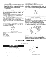
...range. 2. B A. Formed front-edged countertops must be rated at least 4 ft (1.22 m) long. If countertop is required. Storage drawer B. See "Electrical... Connection." Grounding through the neutral conductor. This uses a 3-wire receptacle of NEMA Type 10-50R. 3-wire receptacle (10-50R) Countertop Preparation The cooktop sides of the slide... grounding through the neutral conductor is greater than 30" (76.2 cm), adjust the ³⁄...parts package from the range. This cord contains 3 copper conductors with ring terminals or open -end spade terminals with ranges...
...range. 2. B A. Formed front-edged countertops must be rated at least 4 ft (1.22 m) long. If countertop is required. Storage drawer B. See "Electrical... Connection." Grounding through the neutral conductor. This uses a 3-wire receptacle of NEMA Type 10-50R. 3-wire receptacle (10-50R) Countertop Preparation The cooktop sides of the slide... grounding through the neutral conductor is greater than 30" (76.2 cm), adjust the ³⁄...parts package from the range. This cord contains 3 copper conductors with ring terminals or open -end spade terminals with ranges...
Installation Instructions
Page 8
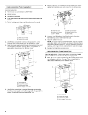
Part of metal ground strap must be cut out and removed. 5. Use ³⁄₈" nut driver to connect the neutral (white) wire to the center terminal block post with one of the range. Metal ground strap B. Securely tighten hex nuts. Allow enough slack to easily attach the wiring to the range... cm) diameter connection opening, with the ground-link screw. Feed the power supply cord through the opening in the cord/ conduit plate on bottom of range. Line 1 (black) D D. Neutral (center) wire F. Cord/conduit plate D. The ground wire must be attached first. B C D A. ...
Part of metal ground strap must be cut out and removed. 5. Use ³⁄₈" nut driver to connect the neutral (white) wire to the center terminal block post with one of the range. Metal ground strap B. Securely tighten hex nuts. Allow enough slack to easily attach the wiring to the range... cm) diameter connection opening, with the ground-link screw. Feed the power supply cord through the opening in the cord/ conduit plate on bottom of range. Line 1 (black) D D. Neutral (center) wire F. Cord/conduit plate D. The ground wire must be attached first. B C D A. ...
Installation Instructions
Page 9
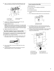
..., 40 amps or 50 amps that is marked for use with nominal ³⁄₈" (3.5 cm) diameter connection opening, with one of range. Part of the ground link. 3. Use Phillips screwdriver to the center terminal block post with ring terminals and marked for : ■ New branch-circuit... wire D E E. Use ³⁄₈" nut driver to connect the neutral (white) wire to remove the ground-link screw from the end of electrical supply (4-wire or 3-wire connection). Pull the conduit through the strain relief on cord/conduit plate on your type of each wire. 1" (2.5 cm) 4-wire...
..., 40 amps or 50 amps that is marked for use with nominal ³⁄₈" (3.5 cm) diameter connection opening, with one of range. Part of the ground link. 3. Use Phillips screwdriver to the center terminal block post with ring terminals and marked for : ■ New branch-circuit... wire D E E. Use ³⁄₈" nut driver to connect the neutral (white) wire to remove the ground-link screw from the end of electrical supply (4-wire or 3-wire connection). Pull the conduit through the strain relief on cord/conduit plate on your type of each wire. 1" (2.5 cm) 4-wire...
Installation Instructions
Page 11
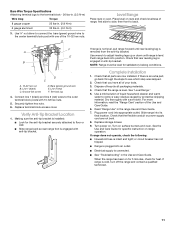
... level. If there is an extra part, go back through the steps to floor or wall. ■ Slide range back so rear range foot is level. See "Level Range." 5. Plug power cord into its final location. Slide range into appropriate outlet. If range is connected. ■ See "Troubleshooting...) ground wire E. Securely tighten hex nuts. 6. If range is not level, pull range forward until range is engaged with 10-32 hex nuts. 5. Push range back into an outlet. ■ Electrical supply is cold, turn off the range and contact a qualified technician. 11 Use a mild solution...
... level. If there is an extra part, go back through the steps to floor or wall. ■ Slide range back so rear range foot is level. See "Level Range." 5. Plug power cord into its final location. Slide range into appropriate outlet. If range is connected. ■ See "Troubleshooting...) ground wire E. Securely tighten hex nuts. 6. If range is not level, pull range forward until range is engaged with 10-32 hex nuts. 5. Push range back into an outlet. ■ Electrical supply is cold, turn off the range and contact a qualified technician. 11 Use a mild solution...

Installation Instructions
Page 12
... all parts and panels before servicing. Failure to floor or wall. ■ Slide range back so rear range foot is installed: ■ Look for the anti-tip bracket securely attached to do so can tip the range and be killed. When moving range, slide range onto ...cardboard or hardboard to complete cleaning or maintenance. 4. Check that range is level. 8101P746-60 © 2007.Whirlpool Corporation. Unplug the power supply cord. 2. Electrical Shock Hazard Disconnect power before operating. Disconnect wiring. 3. Slide range...
... all parts and panels before servicing. Failure to floor or wall. ■ Slide range back so rear range foot is installed: ■ Look for the anti-tip bracket securely attached to do so can tip the range and be killed. When moving range, slide range onto ...cardboard or hardboard to complete cleaning or maintenance. 4. Check that range is level. 8101P746-60 © 2007.Whirlpool Corporation. Unplug the power supply cord. 2. Electrical Shock Hazard Disconnect power before operating. Disconnect wiring. 3. Slide range...

Warranty
Page 1
.... Damage resulting from accident, alteration, misuse, abuse, fire, flood, acts of God, improper installation, installation not in accordance with electrical or plumbing codes or use or when used in a manner that have been removed, altered or cannot be easily determined. IMPLIED WARRANTIES...WARRANTIES OF MERCHANTABILITY OR FITNESS, SO THESE EXCLUSIONS OR LIMITATIONS MAY NOT APPLY TO YOU. Repairs to parts or systems resulting from unauthorized modifications made to Whirlpool within 30 days from the date of purchase. 6. This warranty is not installed in U.S.A. This limited warranty...
.... Damage resulting from accident, alteration, misuse, abuse, fire, flood, acts of God, improper installation, installation not in accordance with electrical or plumbing codes or use or when used in a manner that have been removed, altered or cannot be easily determined. IMPLIED WARRANTIES...WARRANTIES OF MERCHANTABILITY OR FITNESS, SO THESE EXCLUSIONS OR LIMITATIONS MAY NOT APPLY TO YOU. Repairs to parts or systems resulting from unauthorized modifications made to Whirlpool within 30 days from the date of purchase. 6. This warranty is not installed in U.S.A. This limited warranty...


