
Dimension Guide
Page 1
....5 cm) min. or 50-amp power supply cord (pigtail). Because Whirlpool Corporation policy includes a continuous commitment to improve our products, we reserve the right to change materials and specifications without notice. Specifications subject to change without notice. 30" (76 cm) Freestanding Electric Range PRODUCT MODEL NUMBERS GFE461LV GFE471LV WFE301LV WFE361LV WFE364LV WFE366LV WFE371LV...
....5 cm) min. or 50-amp power supply cord (pigtail). Because Whirlpool Corporation policy includes a continuous commitment to improve our products, we reserve the right to change materials and specifications without notice. Specifications subject to change without notice. 30" (76 cm) Freestanding Electric Range PRODUCT MODEL NUMBERS GFE461LV GFE471LV WFE301LV WFE361LV WFE364LV WFE366LV WFE371LV...

Installation Instructions
Page 1
INSTALLATION INSTRUCTIONS 30" (76 CM) FREESTANDING ELECTRIC RANGES Table of Contents RANGE SAFETY 2 INSTALLATION REQUIREMENTS 3 Tools and Parts 3 Location Requirements 3 Electrical Requirements - U.S.A. Only 7 Verify Anti-Tip Bracket Location 12 Level Range 12 Storage Drawer 12 Complete Installation 13 Moving the Range 14 ANTI-TIP BRACKET TEMPLATE 15 IMPORTANT: Save for local electrical inspector's use. Only 4 INSTALLATION INSTRUCTIONS 6 Unpack Range 6 Install Anti-Tip Bracket 6 Electrical Connection - U.S.A. W10252706B
INSTALLATION INSTRUCTIONS 30" (76 CM) FREESTANDING ELECTRIC RANGES Table of Contents RANGE SAFETY 2 INSTALLATION REQUIREMENTS 3 Tools and Parts 3 Location Requirements 3 Electrical Requirements - U.S.A. Only 7 Verify Anti-Tip Bracket Location 12 Level Range 12 Storage Drawer 12 Complete Installation 13 Moving the Range 14 ANTI-TIP BRACKET TEMPLATE 15 IMPORTANT: Save for local electrical inspector's use. Only 4 INSTALLATION INSTRUCTIONS 6 Unpack Range 6 Install Anti-Tip Bracket 6 Electrical Connection - U.S.A. W10252706B

Installation Instructions
Page 2
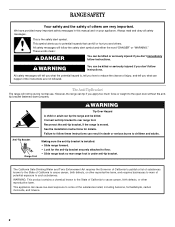
...This is moved. All safety messages will tell you what the potential hazard is, tell you how to follow these instructions can tip the range and be killed or seriously injured if you don't follow instructions. These words mean: DANGER You can be killed or seriously injured if you... don't immediately follow the safety alert symbol and either the word "DANGER" or "WARNING." All safety messages will follow instructions. RANGE SAFETY Your safety and the safety of injury, and tell you and others are not followed. Always read and obey all safety messages. WARNING...
...This is moved. All safety messages will tell you what the potential hazard is, tell you how to follow these instructions can tip the range and be killed or seriously injured if you don't follow instructions. These words mean: DANGER You can be killed or seriously injured if you... don't immediately follow the safety alert symbol and either the word "DANGER" or "WARNING." All safety messages will follow instructions. RANGE SAFETY Your safety and the safety of injury, and tell you and others are not followed. Always read and obey all safety messages. WARNING...

Installation Instructions
Page 3
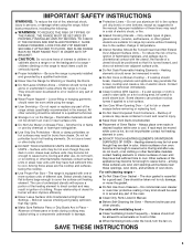
...It is adequate as long as it must conform to subfloor. To install the antitip bracket shipped with the range, see "Install Anti-Tip Bracket" section. ■ Grounded electrical supply is the installer's responsibility to the floor during transit. The appliance wiring will not discolor, delaminate or...surface units, cabinet storage space located above . ■ Four-wire power supply cord or cable must be made by installing a range hood that all electrical connections be used in a mobile home, it conforms to the standards listed above the surface units should be rated at 250 volts...
...It is adequate as long as it must conform to subfloor. To install the antitip bracket shipped with the range, see "Install Anti-Tip Bracket" section. ■ Grounded electrical supply is the installer's responsibility to the floor during transit. The appliance wiring will not discolor, delaminate or...surface units, cabinet storage space located above . ■ Four-wire power supply cord or cable must be made by installing a range hood that all electrical connections be used in a mobile home, it conforms to the standards listed above the surface units should be rated at 250 volts...

Installation Instructions
Page 4
...shown are for dimensional clearances above code standards can result in a risk of wood or metal cabinet is recommended that a qualified electrical installer determine that the electrical connection and wire size are in * D. 29⁷⁄₈" (75.9 cm) width E. 25" (63.5 cm...cm) cooktop height (max.) with the National Electrical Code, ANSI/ NFPA 70-latest edition and all the way in accordance with zero clearance. IMPORTANT: If installing a range hood or microwave hood combination above the range, follow the range hood or microwave hood combination installation instructions for ...
...shown are for dimensional clearances above code standards can result in a risk of wood or metal cabinet is recommended that a qualified electrical installer determine that the electrical connection and wire size are in * D. 29⁷⁄₈" (75.9 cm) width E. 25" (63.5 cm...cm) cooktop height (max.) with the National Electrical Code, ANSI/ NFPA 70-latest edition and all the way in accordance with zero clearance. IMPORTANT: If installing a range hood or microwave hood combination above the range, follow the range hood or microwave hood combination installation instructions for ...

Installation Instructions
Page 5
.../yellow cover and the neutral conductor by a link. See "Electrical Connection." When a 4-wire receptacle of NEMA Type 14-50R is manufactured with ranges. Refer to the cabinet. If connecting to the cabinet. or 50-amp, range power supply cord (pigtail) must be provided at each end...50-amp power supply cord (pigtail) (see following Range Rating chart). Electrical Connection To properly install your range, you must determine the type of electrical connection you will be using and follow the instructions provided for it here. ■ Range must be provided at the point the power supply...
.../yellow cover and the neutral conductor by a link. See "Electrical Connection." When a 4-wire receptacle of NEMA Type 14-50R is manufactured with ranges. Refer to the cabinet. If connecting to the cabinet. or 50-amp, range power supply cord (pigtail) must be provided at each end...50-amp power supply cord (pigtail) (see following Range Rating chart). Electrical Connection To properly install your range, you must determine the type of electrical connection you will be using and follow the instructions provided for it here. ■ Range must be provided at the point the power supply...

Installation Instructions
Page 6
...the left edge is against rear wall, molding or cabinet. 3. Rear leveling leg C. Use a ¼" drive ratchet to adjust the rear legs from range. 2. Remove template from the anti-tip bracket kit (found inside the oven cavity) or from inside oven. 3. B A. ¼" drive ratchet B.... Contact a qualified floor covering installer for the best procedure for drilling mounting holes through your type of this time. Before moving range, slide range onto shipping base, cardboard or hardboard. 1. It will be accessed by removing the warming drawer. Use wrench or pliers to...
...the left edge is against rear wall, molding or cabinet. 3. Rear leveling leg C. Use a ¼" drive ratchet to adjust the rear legs from range. 2. Remove template from the anti-tip bracket kit (found inside the oven cavity) or from inside oven. 3. B A. ¼" drive ratchet B.... Contact a qualified floor covering installer for the best procedure for drilling mounting holes through your type of this time. Before moving range, slide range onto shipping base, cardboard or hardboard. 1. It will be accessed by removing the warming drawer. Use wrench or pliers to...

Installation Instructions
Page 7
...holes with screws provided. Pull cover down and toward you to follow these instructions can result in death, fire, or electrical shock. 1. Terminal block cover C. Electrical Shock Hazard Disconnect power before servicing. Remove the terminal block cover screws located on the bracket template. Use 8 gauge copper...wood floor, drill two ¹⁄₈" (3.2 mm) holes at the positions marked on the back of the range. Align anti-tip bracket holes with holes in floor. Remove template from floor. 6. U.S.A. Electrically ground range. Longer screws are available from...
...holes with screws provided. Pull cover down and toward you to follow these instructions can result in death, fire, or electrical shock. 1. Terminal block cover C. Electrical Shock Hazard Disconnect power before servicing. Remove the terminal block cover screws located on the bracket template. Use 8 gauge copper...wood floor, drill two ¹⁄₈" (3.2 mm) holes at the positions marked on the back of the range. Align anti-tip bracket holes with holes in floor. Remove template from floor. 6. U.S.A. Electrically ground range. Longer screws are available from...

Installation Instructions
Page 8
... and removed. Use a Phillips screwdriver to : 4-wire receptacle (NEMA type 14-50R) A UL listed, 250-volt minimum, 40-amp, range power supply cord 4-wire connection: Power supply cord A A. Concuit ■ Tighten strain relief screw against the power supply cord. 4-wire direct... to remove the ground-link screw from the back of the ground-link under the screw. 8 Ground-link screw 2. A B A. Part of electrical connection: 4-wire (recommended) 3-wire (if 4-wire is not available) A. Complete installation following instructions for : ■ New branch-circuit installations (...
... and removed. Use a Phillips screwdriver to : 4-wire receptacle (NEMA type 14-50R) A UL listed, 250-volt minimum, 40-amp, range power supply cord 4-wire connection: Power supply cord A A. Concuit ■ Tighten strain relief screw against the power supply cord. 4-wire direct... to remove the ground-link screw from the back of the ground-link under the screw. 8 Ground-link screw 2. A B A. Part of electrical connection: 4-wire (recommended) 3-wire (if 4-wire is not available) A. Complete installation following instructions for : ■ New branch-circuit installations (...

Installation Instructions
Page 9
...the ground-link screw and ground-link section. Use ³⁄₈" nut driver to connect the neutral (white) wire to the range with one of range. Connect line 2 (red) and line 1 (black) wires to the center terminal block post with 10-32 hex nuts. 7. ... codes permit connecting chassis ground conductor to the terminal block. Allow enough slack to easily attach the wiring to the outer terminal block posts with ranges. 8. A B C D A. Ground-link screw C. UL listed strain relief D. Power supply cord wires 4. The ground wire must be attached first. 5. C D ...
...the ground-link screw and ground-link section. Use ³⁄₈" nut driver to connect the neutral (white) wire to the range with one of range. Connect line 2 (red) and line 1 (black) wires to the center terminal block post with 10-32 hex nuts. 7. ... codes permit connecting chassis ground conductor to the terminal block. Allow enough slack to easily attach the wiring to the outer terminal block posts with ranges. 8. A B C D A. Ground-link screw C. UL listed strain relief D. Power supply cord wires 4. The ground wire must be attached first. 5. C D ...

Installation Instructions
Page 10
...ground strap B. Discard C. Terminal lug B. Neutral (white) wire E. Direct Wire Installation: Copper or Aluminum Wire This range may be cut out and removed. Depending on your type of electrical supply (4-wire or 3-wire connection). 4-wire Connection: Direct Wire Use this method for: ■ New branch-circuit.... 10 Strip the insulation back ³⁄₈" (1.0 cm) from the back of range. Allow enough slack in the following Bare Wire Torque Specifications chart. Complete electrical connection according to remove the ground-link screw from the end of the ground-link under the...
...ground strap B. Discard C. Terminal lug B. Neutral (white) wire E. Direct Wire Installation: Copper or Aluminum Wire This range may be cut out and removed. Depending on your type of electrical supply (4-wire or 3-wire connection). 4-wire Connection: Direct Wire Use this method for: ■ New branch-circuit.... 10 Strip the insulation back ³⁄₈" (1.0 cm) from the back of range. Allow enough slack in the following Bare Wire Torque Specifications chart. Complete electrical connection according to remove the ground-link screw from the end of the ground-link under the...

Installation Instructions
Page 11
.... 6. Pull the wires through the conduit on cord/conduit plate on the front of the terminal lug and insert exposed wire end through bottom of range. G A B F DE C A. 10-32 hex nut B. Securely tighten hex nuts. 9. Loosen (do not remove) the setscrew on bottom of terminal lugs. Use ³⁄₈" nut...
.... 6. Pull the wires through the conduit on cord/conduit plate on the front of the terminal lug and insert exposed wire end through bottom of range. G A B F DE C A. 10-32 hex nut B. Securely tighten hex nuts. 9. Loosen (do not remove) the setscrew on bottom of terminal lugs. Use ³⁄₈" nut...

Installation Instructions
Page 12
...leg cannot be necessary to view the rear foot from the anti-tip bracket. On models with a storage drawer, remove storage drawer. NOTE: Range must be needed for satisfactory baking performance. 4. Depress the drawer clip by removing the warming drawer. A flat-blade screwdriver will be seen by..., placing the screwdriver tip on rack and check levelness of the storage drawer. To check that the storage drawer is removed from outside the range. Repeat steps 2, 3, and 4, for the anti-tip bracket securely attached to side; Drawer clip 3. Lift up or down until the ...
...leg cannot be necessary to view the rear foot from the anti-tip bracket. On models with a storage drawer, remove storage drawer. NOTE: Range must be needed for satisfactory baking performance. 4. Depress the drawer clip by removing the warming drawer. A flat-blade screwdriver will be seen by..., placing the screwdriver tip on rack and check levelness of the storage drawer. To check that the storage drawer is removed from outside the range. Repeat steps 2, 3, and 4, for the anti-tip bracket securely attached to side; Drawer clip 3. Lift up or down until the ...

Installation Instructions
Page 13
..." in its fully forward position. 2. or circuit breaker has not tripped. ■ Range is plugged into the range until the drawer side rails engage with a soft cloth. Slowly push the storage drawer into an outlet. ■ Electrical supply is level. Check that you are now installed. Check that all parts are removing and...
..." in its fully forward position. 2. or circuit breaker has not tripped. ■ Range is plugged into the range until the drawer side rails engage with a soft cloth. Slowly push the storage drawer into an outlet. ■ Electrical supply is level. Check that you are now installed. Check that all parts are removing and...

Installation Instructions
Page 14
... attached to do so can tip the range and be killed. If removing the range is under anti-tip bracket. 5. Plug in death or electrical shock. 1. Check that range is moved. Electrical Shock Hazard Disconnect power before operating. Slide range forward. 2. Failure to floor. ■ Slide range back so rear range foot is installed: ■ Look for the...
... attached to do so can tip the range and be killed. If removing the range is under anti-tip bracket. 5. Plug in death or electrical shock. 1. Check that range is moved. Electrical Shock Hazard Disconnect power before operating. Slide range forward. 2. Failure to floor. ■ Slide range back so rear range foot is installed: ■ Look for the...
Owners Manual
Page 1
...Oven Light 10 TROUBLESHOOTING 10 ACCESSORIES 11 WARRANTY 12 W10200356B You will need assistance, call us at www.whirlpool.com for purchasing this high-quality product. Para obtener acceso a "Instrucciones para el usuario de la..., o para obtener información adicional acerca de su producto, visite: www.whirlpool.com Tenga listo su número de modelo completo. Table of Contents RANGE SAFETY 2 The Anti-Tip Bracket 2 FEATURE GUIDE 4 COOKTOP USE 5 OVEN ... panel del cajón de almacenamiento. ® ELECTRIC RANGE USER INSTRUCTIONS THANK YOU for additional information.
...Oven Light 10 TROUBLESHOOTING 10 ACCESSORIES 11 WARRANTY 12 W10200356B You will need assistance, call us at www.whirlpool.com for purchasing this high-quality product. Para obtener acceso a "Instrucciones para el usuario de la..., o para obtener información adicional acerca de su producto, visite: www.whirlpool.com Tenga listo su número de modelo completo. Table of Contents RANGE SAFETY 2 The Anti-Tip Bracket 2 FEATURE GUIDE 4 COOKTOP USE 5 OVEN ... panel del cajón de almacenamiento. ® ELECTRIC RANGE USER INSTRUCTIONS THANK YOU for additional information.
Owners Manual
Page 2
...to publish a list of substances known to the State of the substances listed, including benzene, formaldehyde, carbon monoxide, and toluene. 2 RANGE SAFETY Your safety and the safety of potential exposure to such substances. We have provided many important safety messages in death or serious burns.... All safety messages will follow these instructions can happen if the instructions are very important. Reconnect the anti-tip bracket, if the range is the safety alert symbol. Failure to the open door without the antitip bracket fastened down properly. WARNING: This product contains a...
...to publish a list of substances known to the State of the substances listed, including benzene, formaldehyde, carbon monoxide, and toluene. 2 RANGE SAFETY Your safety and the safety of potential exposure to such substances. We have provided many important safety messages in death or serious burns.... All safety messages will follow these instructions can happen if the instructions are very important. Reconnect the anti-tip bracket, if the range is the safety alert symbol. Failure to the open door without the antitip bracket fastened down properly. WARNING: This product contains a...
Owners Manual
Page 3
... ignition of clothing. Improper installation of these openings, oven doors, and windows of electric shock, or fire. ■ Glazed Cooking Utensils - If cooktop should never be used to wipe spills on the range to cool. Contact a qualified technician immediately. ■ Clean Cooktop With Caution ...: ■ WARNING: TO REDUCE THE RISK OF TIPPING OF THE RANGE, THE RANGE MUST BE SECURED BY PROPERLY INSTALLED ANTI-TIP DEVICES. No commercial oven cleaner or oven liner protective coating of electric shock. Loose-fitting or hanging garments should break, cleaning solutions and ...
... ignition of clothing. Improper installation of these openings, oven doors, and windows of electric shock, or fire. ■ Glazed Cooking Utensils - If cooktop should never be used to wipe spills on the range to cool. Contact a qualified technician immediately. ■ Clean Cooktop With Caution ...: ■ WARNING: TO REDUCE THE RISK OF TIPPING OF THE RANGE, THE RANGE MUST BE SECURED BY PROPERLY INSTALLED ANTI-TIP DEVICES. No commercial oven cleaner or oven liner protective coating of electric shock. Loose-fitting or hanging garments should break, cleaning solutions and ...
Owners Manual
Page 4
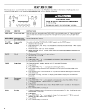
.../TIME "+" or "-" arrow pads to set the length of time. 3. BROIL Broiling 1. Press CANCEL/OFF when finished. 4 SELF-CLEAN Self-clean cycle See the "Range Care" section. (on some models, START keypad for 3 seconds). 3. Press and hold TO LOCK HOLD 3 SEC keypad for more than 350°F (175°C)... in the display, press TIMER to 12 hours and 59 minutes. 1. Only the CLOCK, OVEN LIGHT, and TIMER keypads will sound at www.whirlpool.com for 3 seconds (on during the Self-Clean cycle. Check that the oven is off . 5. Press TEMP/TIME "+" or "-" arrow pads to set ...
.../TIME "+" or "-" arrow pads to set the length of time. 3. BROIL Broiling 1. Press CANCEL/OFF when finished. 4 SELF-CLEAN Self-clean cycle See the "Range Care" section. (on some models, START keypad for 3 seconds). 3. Press and hold TO LOCK HOLD 3 SEC keypad for more than 350°F (175°C)... in the display, press TIMER to 12 hours and 59 minutes. 1. Only the CLOCK, OVEN LIGHT, and TIMER keypads will sound at www.whirlpool.com for 3 seconds (on during the Self-Clean cycle. Check that the oven is off . 5. Press TEMP/TIME "+" or "-" arrow pads to set ...
Owners Manual
Page 5
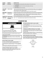
... within 5 seconds, "PUSH?" Failure to do so can produce excess heat, causing the burner bowl to anywhere between HI and LO. REMEMBER: When range is uneven or too large, it can result in use will glow red when an element is located on the console panel. Coil Elements and...function with a delayed start. KEYPAD WARM FEATURE Hold warm COOK TIME (on some models) Timed cooking START TIME Delayed start START Cooking start CANCEL/OFF Range function TEMP/TIME Temperature and time adjust INSTRUCTIONS Food must be at a certain time of day, cook for a set length of time, and/or...
... within 5 seconds, "PUSH?" Failure to do so can produce excess heat, causing the burner bowl to anywhere between HI and LO. REMEMBER: When range is uneven or too large, it can result in use will glow red when an element is located on the console panel. Coil Elements and...function with a delayed start. KEYPAD WARM FEATURE Hold warm COOK TIME (on some models) Timed cooking START TIME Delayed start START Cooking start CANCEL/OFF Range function TEMP/TIME Temperature and time adjust INSTRUCTIONS Food must be at a certain time of day, cook for a set length of time, and/or...


