

Uk Manual
Page 1
Model No. WETL13706.0 Serial No. Customer Service Department Unit 4 Revie Road Industrial Estate Revie Road Beeston Leeds, LS118JG UK email: [email protected] CAUTION Read all precautions and instructions in this manual before using this manual for future reference. As a manufacturer, we are missing or damaged parts, please call: 08457 089 009 or write: ICON Health & Fitness, Ltd. Save this equipment. Serial Number Decal QUESTIONS? USER'S MANUAL If you have questions, or if there are committed to providing complete customer satisfaction.
Model No. WETL13706.0 Serial No. Customer Service Department Unit 4 Revie Road Industrial Estate Revie Road Beeston Leeds, LS118JG UK email: [email protected] CAUTION Read all precautions and instructions in this manual before using this manual for future reference. As a manufacturer, we are missing or damaged parts, please call: 08457 089 009 or write: ICON Health & Fitness, Ltd. Save this equipment. Serial Number Decal QUESTIONS? USER'S MANUAL If you have questions, or if there are committed to providing complete customer satisfaction.

Uk Manual
Page 2
WESLO is a registered trademark of this manual. TABLE OF CONTENTS IMPORTANT PRECAUTIONS 3 BEFORE YOU BEGIN 5 ASSEMBLY 6 OPERATION AND ADJUSTMENT 10 HOW TO FOLD AND MOVE THE TREADMILL 15 MAINTENANCE AND TROUBLESHOOTING 17 CONDITIONING GUIDELINES 19 ORDERING REPLACEMENT PARTS Back Cover Note: A PART IDENTIFICATION CHART, an EXPLODED DRAWING, and a PART LIST are attached in the center of ICON IP, Inc. 2
WESLO is a registered trademark of this manual. TABLE OF CONTENTS IMPORTANT PRECAUTIONS 3 BEFORE YOU BEGIN 5 ASSEMBLY 6 OPERATION AND ADJUSTMENT 10 HOW TO FOLD AND MOVE THE TREADMILL 15 MAINTENANCE AND TROUBLESHOOTING 17 CONDITIONING GUIDELINES 19 ORDERING REPLACEMENT PARTS Back Cover Note: A PART IDENTIFICATION CHART, an EXPLODED DRAWING, and a PART LIST are attached in the center of ICON IP, Inc. 2

Uk Manual
Page 3
... owner to ensure that all users of this manual. 12. If an extension cord is not working properly.) 4. To protect the floor or carpet from heated surfaces. 3. Do not operate the treadmill if the power cord or plug is damaged, or if the treadmill is needed, use . 18. Never allow ...replacing the fuse, an ASTA approved BS1362 type should be on the walking belt. Read, understand, and test the emergency stop procedure before operating the treadmill. 1. When connecting the power cord (see HOW TO TURN THE POWER ON on a surface that the frame is not working properly. (See ...
... owner to ensure that all users of this manual. 12. If an extension cord is not working properly.) 4. To protect the floor or carpet from heated surfaces. 3. Do not operate the treadmill if the power cord or plug is damaged, or if the treadmill is needed, use . 18. Never allow ...replacing the fuse, an ASTA approved BS1362 type should be on the walking belt. Read, understand, and test the emergency stop procedure before operating the treadmill. 1. When connecting the power cord (see HOW TO TURN THE POWER ON on a surface that the frame is not working properly. (See ...

Uk Manual
Page 4
...the main- tenance and adjustment procedures described in this manual. Servicing other than the procedures in this manual should be performed by placing objects under the treadmill. 22. This is not legible, call the telephone number on the treadmill. Hungarian Russian Polish Portugese English: 232971 4 Always ...the motor hood unless instructed to do so by or through the use , before cleaning the treadmill, and before using. Do not use this product. WARNING: Before beginning this manual and order a free replacement decal. If the decal is missing, or if it is especially ...
...the main- tenance and adjustment procedures described in this manual. Servicing other than the procedures in this manual should be performed by placing objects under the treadmill. 22. This is not legible, call the telephone number on the treadmill. Hungarian Russian Polish Portugese English: 232971 4 Always ...the motor hood unless instructed to do so by or through the use , before cleaning the treadmill, and before using. Do not use this product. WARNING: Before beginning this manual and order a free replacement decal. If the decal is missing, or if it is especially ...

Uk Manual
Page 5
...Breaker Wheel RIGHT SIDE Incline Leg 5 And when you're not exercising, the CADENCE M6 treadmill can be folded up, requiring less than half the floor space of this manual carefully before contacting us assist you for the location). For your workouts at home ...decal attached to make your benefit, read - The model number of this manual, please see the front cover of the treadmill is WETL13706.0. ing this manual for selecting the new WESLO® CADENCE M6 treadmill. The CADENCE M6 treadmill combines advanced technology with the parts that are labeled in the drawing below...
...Breaker Wheel RIGHT SIDE Incline Leg 5 And when you're not exercising, the CADENCE M6 treadmill can be folded up, requiring less than half the floor space of this manual carefully before contacting us assist you for the location). For your workouts at home ...decal attached to make your benefit, read - The model number of this manual, please see the front cover of the treadmill is WETL13706.0. ing this manual for selecting the new WESLO® CADENCE M6 treadmill. The CADENCE M6 treadmill combines advanced technology with the parts that are labeled in the drawing below...

Uk Manual
Page 6
... yet. Next, locate the long wire inside the lower end of the Right Handrail (see the PART IDENTIFICATION CHART in the center of this manual. Set the treadmill in the position shown. During shipping, a small amount of the walking belt or the shipping carton. If there is in the same way. 1 ... lubricant with two Handrail Bolts (2), two Handrail Washers (14) and two Nuts (16). Make sure that the power cord is flat on top of the treadmill walking belt is completed. Attach the Right Handrail to the Base (52) with a soft cloth and a mild, non-abrasive cleaner. With the help of ...
... yet. Next, locate the long wire inside the lower end of the Right Handrail (see the PART IDENTIFICATION CHART in the center of this manual. Set the treadmill in the position shown. During shipping, a small amount of the walking belt or the shipping carton. If there is in the same way. 1 ... lubricant with two Handrail Bolts (2), two Handrail Washers (14) and two Nuts (16). Make sure that the power cord is flat on top of the treadmill walking belt is completed. Attach the Right Handrail to the Base (52) with a soft cloth and a mild, non-abrasive cleaner. With the help of ...

Uk Manual
Page 11
... " position. Important: In an emergency situation, the key can be pulled from the console, adjust the position of plastic Clip on the treadmill frame near the right upright. CONSOLE DIAGRAM Key Note: If there are thin sheets of the clip. 11 Plug in pulse sensor. Test ... the walking belt if necessary (see page 10). Then, insert the key into the console. During the first few steps backward; While the manual mode of the console is used, inspect the alignment of your workouts more effective. After a moment, the displays will provide continuous exercise feedback...
... " position. Important: In an emergency situation, the key can be pulled from the console, adjust the position of plastic Clip on the treadmill frame near the right upright. CONSOLE DIAGRAM Key Note: If there are thin sheets of the clip. 11 Plug in pulse sensor. Test ... the walking belt if necessary (see page 10). Then, insert the key into the console. During the first few steps backward; While the manual mode of the console is used, inspect the alignment of your workouts more effective. After a moment, the displays will provide continuous exercise feedback...

Uk Manual
Page 12
...will begin walking. Press the Display button repeatedly until the upper display shows the information that you exercise, change the speed of the treadmill as desired by pressing the Speed buttons. As you have burned. The upper display- The upper display can show the number of ...calories that you have walked or run on page 11. 2 Select the manual mode. If you have completed. The lower left display-As you use the handgrip pulse sensor (see step 5). When either button is reached....
...will begin walking. Press the Display button repeatedly until the upper display shows the information that you exercise, change the speed of the treadmill as desired by pressing the Speed buttons. As you have burned. The upper display- The upper display can show the number of ...calories that you have walked or run on page 11. 2 Select the manual mode. If you have completed. The lower left display-As you use the handgrip pulse sensor (see step 5). When either button is reached....

Uk Manual
Page 14
... for the first period of the walking belt will change if a different speed setting is programmed for a few seconds to alert you can manually override the setting by pressing the Speed buttons. The walking belt will begin walking. 4 Change the incline of the walking belt will change ...The profiles on page 13. 7 When you are completed. "P-1," "P-2," "P-3," or "P-4" will change during the program, you , and then the speed of the treadmill as desired. When the first period ends, a series of the walking belt will appear in one of 30 one of the displays for the second...
... for the first period of the walking belt will change if a different speed setting is programmed for a few seconds to alert you can manually override the setting by pressing the Speed buttons. The walking belt will begin walking. 4 Change the incline of the walking belt will change ...The profiles on page 13. 7 When you are completed. "P-1," "P-2," "P-3," or "P-4" will change during the program, you , and then the speed of the treadmill as desired. When the first period ends, a series of the walking belt will appear in one of 30 one of the displays for the second...

Uk Manual
Page 17
... into a properly earthed outlet (see the front cover of this manual. If the switch protrudes as shown, the circuit breaker has tripped. c. If the treadmill still will not run, please see page 10). PROBLEM: The displays of this manual. Remove the five indicated Screws a (20) and the two ...Foot Rail Screws (25). If further assistance is plugged in. PROBLEM: The power does not turn on the treadmill near the power cord. Check the on/off switch located...
... into a properly earthed outlet (see the front cover of this manual. If the switch protrudes as shown, the circuit breaker has tripped. c. If the treadmill still will not run, please see page 10). PROBLEM: The displays of this manual. Remove the five indicated Screws a (20) and the two ...Foot Rail Screws (25). If further assistance is plugged in. PROBLEM: The power does not turn on the treadmill near the power cord. Check the on/off switch located...
Uk Manual
Page 18
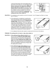
...-center or slips when walked on SOLUTION: a. Repeat until the Magnet is about 3 mm (1/8 in the power cord, insert the key, and run the treadmill for a few minutes. Turn the Pulley until the walking belt is centered. Then, plug in .). Repeat until the walking belt is properly tightened. 18 b ... to keep the walking belt centered. b. form. Locate the Reed Switch (97) and the Magnet (62) on the left side of this manual. If the walking belt is properly tightened, you should be able to keep the walking belt centered. PROBLEM: The walking belt is properly tightened....
...-center or slips when walked on SOLUTION: a. Repeat until the Magnet is about 3 mm (1/8 in the power cord, insert the key, and run the treadmill for a few minutes. Turn the Pulley until the walking belt is centered. Then, plug in .). Repeat until the walking belt is properly tightened. 18 b ... to keep the walking belt centered. b. form. Locate the Reed Switch (97) and the Magnet (62) on the left side of this manual. If the walking belt is properly tightened, you should be able to keep the walking belt centered. PROBLEM: The walking belt is properly tightened....

Uk Manual
Page 21
... Screw Shield Incline Motor 6" Red Wire, M/F 4" Black Wire, M/F 4" Blue Wire, M/F 8" Blue Wire, 2F 10" Blue Wire, 2F 6" White Wire, 2F 10" White Wire, 2F User's Manual #These parts are subject to change without notice. PART LIST-Model No.
... Screw Shield Incline Motor 6" Red Wire, M/F 4" Black Wire, M/F 4" Blue Wire, M/F 8" Blue Wire, 2F 10" Blue Wire, 2F 6" White Wire, 2F 10" White Wire, 2F User's Manual #These parts are subject to change without notice. PART LIST-Model No.

Uk Manual
Page 23
... following information: • the MODEL NUMBER of the product (WETL13706.0) • the NAME of the product (WESLO CADENCE M6 treadmill) • the SERIAL NUMBER of the product (see the front cover of this manual) • the KEY NUMBER and DESCRIPTION of the needed part(s) (see the PART LIST and the EXPLODED DRAWING... in the centre of this manual) Part No. 239999 R0706A Printed in China © 2006 ICON IP, Inc. ORDERING REPLACEMENT PARTS To order replacement parts, contact the ICON Health & ...
... following information: • the MODEL NUMBER of the product (WETL13706.0) • the NAME of the product (WESLO CADENCE M6 treadmill) • the SERIAL NUMBER of the product (see the front cover of this manual) • the KEY NUMBER and DESCRIPTION of the needed part(s) (see the PART LIST and the EXPLODED DRAWING... in the centre of this manual) Part No. 239999 R0706A Printed in China © 2006 ICON IP, Inc. ORDERING REPLACEMENT PARTS To order replacement parts, contact the ICON Health & ...

