
Owner's Manual for 3-Phase UPS 932764
Page 4
...5 openings of the cabinet. • Do not place any angle). Connection Warnings 9 • The power supply for serious personal injury. 7 • The casters are not designed to power modern computer loads and associated peripheral devices. The disconnect device must be three phase rated in this manual... mount the unit with air, oxygen or nitrous oxide. • The UPS system is not connected to an AC supply. • If the UPS system receives power from electric shock. 10 • The UPS system has its own energy source (battery - Keep all recorded magnetic media...
...5 openings of the cabinet. • Do not place any angle). Connection Warnings 9 • The power supply for serious personal injury. 7 • The casters are not designed to power modern computer loads and associated peripheral devices. The disconnect device must be three phase rated in this manual... mount the unit with air, oxygen or nitrous oxide. • The UPS system is not connected to an AC supply. • If the UPS system receives power from electric shock. 10 • The UPS system has its own energy source (battery - Keep all recorded magnetic media...
Owner's Manual for 3-Phase UPS 932764
Page 6
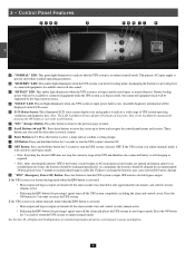
...hour period every 3 months to connected equipment while the UPS system is in bypass mode (auto bypass or manual bypass). The primary AC input supply is present and within standard operating parameters. 5 •B "BATTERY" LED: This amber light illuminates when the UPS system is activated: 11...move the cursor up or down after 10 minutes of inactivity. Failure to recharge the batteries may cause irreversible battery damage. •K "EPO" (Emergency Power Off) Button: Press this button to return to the previous page or menu. • G 8 •H Scroll Buttons ( and ): Press ...
...hour period every 3 months to connected equipment while the UPS system is in bypass mode (auto bypass or manual bypass). The primary AC input supply is present and within standard operating parameters. 5 •B "BATTERY" LED: This amber light illuminates when the UPS system is activated: 11...move the cursor up or down after 10 minutes of inactivity. Failure to recharge the batteries may cause irreversible battery damage. •K "EPO" (Emergency Power Off) Button: Press this button to return to the previous page or menu. • G 8 •H Scroll Buttons ( and ): Press ...
Owner's Manual for 3-Phase UPS 932764
Page 15
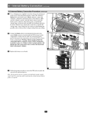
... Battery Connection Procedure (contiinued) •11 Use a voltmeter (user-supplied) to test the voltage of each internal battery pack to the nearest... 240V DC). 3 If several voltmeter tests yield results outside the acceptable DC 240 voltage range, contact Tripp Lite for assistance in determining the possible causes of personal injury and property damage. 6 12 •13 ... If you need to the battery pack's black connector; connect the voltmeter's red probe to protected power. Failure to observe proper polarity will damage the UPS system and create a serious risk of the ...
... Battery Connection Procedure (contiinued) •11 Use a voltmeter (user-supplied) to test the voltage of each internal battery pack to the nearest... 240V DC). 3 If several voltmeter tests yield results outside the acceptable DC 240 voltage range, contact Tripp Lite for assistance in determining the possible causes of personal injury and property damage. 6 12 •13 ... If you need to the battery pack's black connector; connect the voltmeter's red probe to protected power. Failure to observe proper polarity will damage the UPS system and create a serious risk of the ...
Owner's Manual for 3-Phase UPS 932764
Page 22
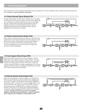
... it down . For more information about switching between operating modes, refer to precision-regulated, pure sine wave AC power that charges the batteries and supplies the 3 inverter. The inverter transforms the DC power to Section 9 - MAIN Q2 Q1 XFMR 4 Q4 LOAD XFMR CB5 STS 8-2 Battery Backup Mode (Single UPS... and ensures that conforms to normal parameters, then the UPS system automatically switches to auto bypass mode to continue supplying power to connected equipment. Q3 MAIN Q2 Q1 XFMR 7 8-3 Auto Bypass Mode (Single UPS) If the inverter malfunctions due to ...
... it down . For more information about switching between operating modes, refer to precision-regulated, pure sine wave AC power that charges the batteries and supplies the 3 inverter. The inverter transforms the DC power to Section 9 - MAIN Q2 Q1 XFMR 4 Q4 LOAD XFMR CB5 STS 8-2 Battery Backup Mode (Single UPS... and ensures that conforms to normal parameters, then the UPS system automatically switches to auto bypass mode to continue supplying power to connected equipment. Q3 MAIN Q2 Q1 XFMR 7 8-3 Auto Bypass Mode (Single UPS) If the inverter malfunctions due to ...

Owner's Manual for 3-Phase UPS 932764
Page 26
...system is ready for 3 seconds (until you hear a beep), then release the button. The inverter will activate and use stored DC battery power to supply AC power to connected equipment. After a brief initialization process, the LCD screen will show "ON AUTO BYPASS", the "BYPASS" LED will illuminate and ... the bypass power source. 3 3 •4 Switch on the bypass input breaker switch Q2 and then output circuit breaker switch Q4. The "BYPASS" LED will darken and the "NORMAL" LED will illuminate. Q3 Output Manual Bypass Bypass Input Main Input A 14 3 26 On the SU40K, turn on ...
...system is ready for 3 seconds (until you hear a beep), then release the button. The inverter will activate and use stored DC battery power to supply AC power to connected equipment. After a brief initialization process, the LCD screen will show "ON AUTO BYPASS", the "BYPASS" LED will illuminate and ... the bypass power source. 3 3 •4 Switch on the bypass input breaker switch Q2 and then output circuit breaker switch Q4. The "BYPASS" LED will darken and the "NORMAL" LED will illuminate. Q3 Output Manual Bypass Bypass Input Main Input A 14 3 26 On the SU40K, turn on ...

Owner's Manual for 3-Phase UPS 932764
Page 35
Connected equipment loads will lose power if the bypass power source fails. 10 11 12 4 13 14 35 10 - Display and Configuration (continued) 1 10-3-1 Status Display (continued) •2 The loads are supplied by bypass source due to initial startup of the UPS. 2 3 4 5 2 •3 The UPS is starting up by battery power. 6 7 8 9 3 •4 The UPS system is in auto bypass mode.
Connected equipment loads will lose power if the bypass power source fails. 10 11 12 4 13 14 35 10 - Display and Configuration (continued) 1 10-3-1 Status Display (continued) •2 The loads are supplied by bypass source due to initial startup of the UPS. 2 3 4 5 2 •3 The UPS is starting up by battery power. 6 7 8 9 3 •4 The UPS system is in auto bypass mode.

Owner's Manual for 3-Phase UPS 932764
Page 36
Display and Configuration (continued) 1 10-3-1 Status Display (continued) •5 The UPS system is operating in battery backup mode. The loads are supplied by 6 battery power. 7 8 9 6 •7 The UPS is in online (normal) mode. 10 - Connected 2 equipment loads will receive battery backup power if the mains (utility or generator) power source fails. 3 4 5 5 •6 The UPS is performing the "battery test". 10 11 12 13 7 14 36
Display and Configuration (continued) 1 10-3-1 Status Display (continued) •5 The UPS system is operating in battery backup mode. The loads are supplied by 6 battery power. 7 8 9 6 •7 The UPS is in online (normal) mode. 10 - Connected 2 equipment loads will receive battery backup power if the mains (utility or generator) power source fails. 3 4 5 5 •6 The UPS is performing the "battery test". 10 11 12 13 7 14 36
Owner's Manual for 3-Phase UPS 932764
Page 55
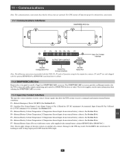
... 11-2 SNMPWEBCARD Slot 8 Remove the cover panel to install a Tripp Lite SNMPWEBCARD accessory. Communications 1 Note: The communications connections described in order to receive commands and monitor external battery conditions: P1-Remote Emergency Power Off (EPO) (See Section 11-4.) 10 P2-Auxiliary Dry Contact...Temperature Sensor Inputs from external battery cabinets. See Section 11-6.) P7-External Battery Status (For use with battery status cable supplied with external battery cabinets-BP480V26B or BP480V40C.) 12 Note: Do not apply voltages to the UPS may result. See Section...
... 11-2 SNMPWEBCARD Slot 8 Remove the cover panel to install a Tripp Lite SNMPWEBCARD accessory. Communications 1 Note: The communications connections described in order to receive commands and monitor external battery conditions: P1-Remote Emergency Power Off (EPO) (See Section 11-4.) 10 P2-Auxiliary Dry Contact...Temperature Sensor Inputs from external battery cabinets. See Section 11-6.) P7-External Battery Status (For use with battery status cable supplied with external battery cabinets-BP480V26B or BP480V40C.) 12 Note: Do not apply voltages to the UPS may result. See Section...

Owner's Manual for 3-Phase UPS 932764
Page 56
...information. 10 11-7 External Battery Status Input The external battery cabinet status input connection (P7) allows the UPS system to a user-supplied remote switch, following the circuit diagram below. G4 5 11-5 Auxiliary Dry Contact Input Circuit Diagram The auxiliary dry contact input connections (...information. 12 13 14 56 These contacts are normally open . 11 - Communications (continued) 1 11-4 Remote Emergency Power Off (EPO) Circuit Diagram The Remote Emergency Power Off (EPO) input connection (P1) allows you to connect the UPS system to bypass. Connect EPO input to ...
...information. 10 11-7 External Battery Status Input The external battery cabinet status input connection (P7) allows the UPS system to a user-supplied remote switch, following the circuit diagram below. G4 5 11-5 Auxiliary Dry Contact Input Circuit Diagram The auxiliary dry contact input connections (...information. 12 13 14 56 These contacts are normally open . 11 - Communications (continued) 1 11-4 Remote Emergency Power Off (EPO) Circuit Diagram The Remote Emergency Power Off (EPO) input connection (P1) allows you to connect the UPS system to bypass. Connect EPO input to ...

