Owner's Manual for 3-Phase UPS 932764
Page 3
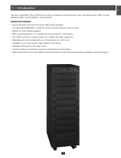
...inverter technology • Low input current THD allows 1:1 generator sizing for maximum efficiency and cost savings • Internal N+1 power module redundancy 3 • Built-in parallel redundancy (1+1) capability for increased capacity or fault-tolerance • Up to ... Introduction 1 Tripp Lite's SmartOnline 3-Phase UPS Systems are ideal for extended battery backup runtime • High-resolution LCD status screen simplifies operation and delivers detailed operational information, including system block diagrams 5 6 7 8 9 10 11 12 13 14 3 up and protecting data centers...
...inverter technology • Low input current THD allows 1:1 generator sizing for maximum efficiency and cost savings • Internal N+1 power module redundancy 3 • Built-in parallel redundancy (1+1) capability for increased capacity or fault-tolerance • Up to ... Introduction 1 Tripp Lite's SmartOnline 3-Phase UPS Systems are ideal for extended battery backup runtime • High-resolution LCD status screen simplifies operation and delivers detailed operational information, including system block diagrams 5 6 7 8 9 10 11 12 13 14 3 up and protecting data centers...
Owner's Manual for 3-Phase UPS 932764
Page 15
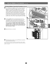
...280V DC (nominal 240V DC). 3 If several voltmeter tests yield results outside the acceptable DC 240 voltage range, contact Tripp Lite for assistance in determining the possible causes of the incorrect voltage reading before proceeding. 11 4 •12 Connect the black... the battery pack's connectors. Make sure the voltmeter's probes touch the metal contacts inside the UPS system's battery compartment. Failure to protected power. Internal Battery Connection (continued) 1 6-2 Internal Battery Connection Procedure (contiinued) •11 Use a voltmeter (user-supplied) to test...
...280V DC (nominal 240V DC). 3 If several voltmeter tests yield results outside the acceptable DC 240 voltage range, contact Tripp Lite for assistance in determining the possible causes of the incorrect voltage reading before proceeding. 11 4 •12 Connect the black... the battery pack's connectors. Make sure the voltmeter's probes touch the metal contacts inside the UPS system's battery compartment. Failure to protected power. Internal Battery Connection (continued) 1 6-2 Internal Battery Connection Procedure (contiinued) •11 Use a voltmeter (user-supplied) to test...
Owner's Manual for 3-Phase UPS 932764
Page 19
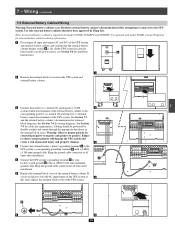
... battery cabinets that the external battery 3 cabinet breaker switch A is off. (If the UPS system has already been wired to an AC power source, see Section 9-6 for shutdown A instructions.) 4 1 •2 Remove the terminal block covers from the UPS system and 5 external ...8226;4 Connect the external battery cabinet's grounding terminal A to your facility's earth ground B with model SU40K. It is required with a 4 AWG (5.189 mm) ground cable. Cabling should be protected by Tripp Lite. 2 Note: An external battery cabinet is optional with a 4 AWG (5.189 mm) minimum ground cable...
... battery cabinets that the external battery 3 cabinet breaker switch A is off. (If the UPS system has already been wired to an AC power source, see Section 9-6 for shutdown A instructions.) 4 1 •2 Remove the terminal block covers from the UPS system and 5 external ...8226;4 Connect the external battery cabinet's grounding terminal A to your facility's earth ground B with model SU40K. It is required with a 4 AWG (5.189 mm) ground cable. Cabling should be protected by Tripp Lite. 2 Note: An external battery cabinet is optional with a 4 AWG (5.189 mm) minimum ground cable...

Owner's Manual for 3-Phase UPS 932764
Page 27
... UPS is in BYPASS mode. 1 •3 Turn OFF the MAIN INPUT circuit breaker Q1. •4 Wait until the Power Module fans turn OFF the Q4 Q3 Q2 Q1 BATTERY BREAKER (on the SU40K unit, the BATTERY BREAKER is on the back of the UPS; on the 60K and 80K units, the BATTERY...: If the UPS system remains off or place the UPS system in NORMAL mode (green LED ON, LCD displays "Load Protected - The LCD 3-7 Bypass Input Input will eliminate the AC power output for the internal battery) is on the back of the UPS; Note: Some external battery cabinets may take a minute or...
... UPS is in BYPASS mode. 1 •3 Turn OFF the MAIN INPUT circuit breaker Q1. •4 Wait until the Power Module fans turn OFF the Q4 Q3 Q2 Q1 BATTERY BREAKER (on the SU40K unit, the BATTERY BREAKER is on the back of the UPS; on the 60K and 80K units, the BATTERY...: If the UPS system remains off or place the UPS system in NORMAL mode (green LED ON, LCD displays "Load Protected - The LCD 3-7 Bypass Input Input will eliminate the AC power output for the internal battery) is on the back of the UPS; Note: Some external battery cabinets may take a minute or...

Owner's Manual for 3-Phase UPS 932764
Page 28
...are within the recommended specifications. 1111. Attempting to 2 and a different "Parallel ID" that the input power source matches the rating (voltage, frequency and phase) of the UPS systems. 12 • Each ... come on and the LCD will transfer to NORMAL mode (green LED ON and LCD displays "Load Protected-On Line Mode"). 99. Q4 Q3 Q2 Q1 Output Manual Bypass Bypass Input Main Input Q2 Q4 ...breaker Q1 . Do not attempt to the connected equipment load. 13 14 28 on the SU20K and SU40K units, the BATTERY BREAKER is present, press the UP or DOWN 8 arrows to NORMAL mode from ...
...are within the recommended specifications. 1111. Attempting to 2 and a different "Parallel ID" that the input power source matches the rating (voltage, frequency and phase) of the UPS systems. 12 • Each ... come on and the LCD will transfer to NORMAL mode (green LED ON and LCD displays "Load Protected-On Line Mode"). 99. Q4 Q3 Q2 Q1 Output Manual Bypass Bypass Input Main Input Q2 Q4 ...breaker Q1 . Do not attempt to the connected equipment load. 13 14 28 on the SU20K and SU40K units, the BATTERY BREAKER is present, press the UP or DOWN 8 arrows to NORMAL mode from ...
