
Toshiba Online Users Guide for Tecra M5
Page 8
...Statements as identified in the user airports), you are encouraged to ask for authorization to use of the organization. Nevertheless, the TOSHIBA Wireless LAN Mini PCI Card shall be used for this transmitter must not be co-located or operating in conjunction with any other... LAN may be less than the electromagnetic energy emitted by wireless devices like other antenna or transmitter. In normal operating configuration, the LCD in a specific organization or environment (e.g. If you are uncertain of wireless devices in the upright position, the distance between the antenna...
...Statements as identified in the user airports), you are encouraged to ask for authorization to use of the organization. Nevertheless, the TOSHIBA Wireless LAN Mini PCI Card shall be used for this transmitter must not be co-located or operating in conjunction with any other... LAN may be less than the electromagnetic energy emitted by wireless devices like other antenna or transmitter. In normal operating configuration, the LCD in a specific organization or environment (e.g. If you are uncertain of wireless devices in the upright position, the distance between the antenna...

Toshiba Online Users Guide for Tecra M5
Page 80
For the best video quality, always use a properly shielded cable. HINT: Toshiba recommends using a cable no longer than 20 feet (approximately 6 meters). If you must purchase an S-video cable. Also, refer to the documentation for the type .... Using a poor quality cable may result in detail. 80 Getting Started Using external display devices Using external display devices Your computer comes with a built-in LCD display, but you can also connect three different types of external display devices to one of two available video ports: ❖ A television via the S-video...
For the best video quality, always use a properly shielded cable. HINT: Toshiba recommends using a cable no longer than 20 feet (approximately 6 meters). If you must purchase an S-video cable. Also, refer to the documentation for the type .... Using a poor quality cable may result in detail. 80 Getting Started Using external display devices Using external display devices Your computer comes with a built-in LCD display, but you can also connect three different types of external display devices to one of two available video ports: ❖ A television via the S-video...
Toshiba Online Users Guide for Tecra M5
Page 81
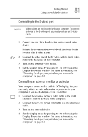
... S-video port, you need a larger screen. Connecting an external monitor or projector Your computer comes with the device for the location of its S-video in LCD display, but you can easily attach an external monitor or projector to your computer.
... S-video port, you need a larger screen. Connecting an external monitor or projector Your computer comes with the device for the location of its S-video in LCD display, but you can easily attach an external monitor or projector to your computer.

Toshiba Online Users Guide for Tecra M5
Page 83
... a maximum resolution of 640 x 480 and your external display device, you must support a resolution of 800 x 600 or higher. See the documentation supplied with the LCD Display Stretch option enabled and the display area (resolution) set to 640 x 480 or 800 x 600, the image on the screen. Getting Started Using external...
... a maximum resolution of 640 x 480 and your external display device, you must support a resolution of 800 x 600 or higher. See the documentation supplied with the LCD Display Stretch option enabled and the display area (resolution) set to 640 x 480 or 800 x 600, the image on the screen. Getting Started Using external...
Toshiba Online Users Guide for Tecra M5
Page 186
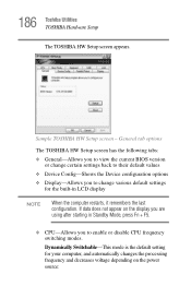
... Setup screen appears. General tab options The TOSHIBA HW Setup screen has the following tabs: ❖ General-Allows you to view the current BIOS version or change various default settings for your computer, ... Switchable-This mode is the default setting for the built-in Standby Mode, press Fn + F5. ❖ CPU-Allows you are using after starting in LCD display NOTE When the computer restarts, it remembers the last configuration. If data does not appear on the power source: Sample...
... Setup screen appears. General tab options The TOSHIBA HW Setup screen has the following tabs: ❖ General-Allows you to view the current BIOS version or change various default settings for your computer, ... Switchable-This mode is the default setting for the built-in Standby Mode, press Fn + F5. ❖ CPU-Allows you are using after starting in LCD display NOTE When the computer restarts, it remembers the last configuration. If data does not appear on the power source: Sample...

Toshiba Online Users Guide for Tecra M5
Page 301
... Hypertext Markup Language IEEE Institute of Electrical and Electronics Engineers I/O input/output IRQ interrupt request ISP Internet service provider KB kilobyte LAN local area network LCD liquid crystal display LPT1 line printer port 1 (parallel port) LSI large-scale integration MB megabyte MIDI Musical Instrument Digital Interface PC personal computer PCI Peripheral...
... Hypertext Markup Language IEEE Institute of Electrical and Electronics Engineers I/O input/output IRQ interrupt request ISP Internet service provider KB kilobyte LAN local area network LCD liquid crystal display LPT1 line printer port 1 (parallel port) LSI large-scale integration MB megabyte MIDI Musical Instrument Digital Interface PC personal computer PCI Peripheral...

Toshiba Online Users Guide for Tecra M5
Page 302
A liquid crystal display (LCD) made from a microprocessor to residential and commercial wall outlets. An adapter can take a number of forms, from an array of liquid crystal cells using active-...
A liquid crystal display (LCD) made from a microprocessor to residential and commercial wall outlets. An adapter can take a number of forms, from an array of liquid crystal cells using active-...
Toshiba Online Users Guide for Tecra M5
Page 309
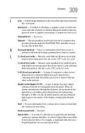
.... A key or combination of the display, creating light and dark pixels. Memory cache built into memory for processing. L2 (level two) cache - liquid crystal display (LCD) - A type of display that you use to create a complete screen image. To move information from its physical drives. logical drive -
.... A key or combination of the display, creating light and dark pixels. Memory cache built into memory for processing. L2 (level two) cache - liquid crystal display (LCD) - A type of display that you use to create a complete screen image. To move information from its physical drives. logical drive -

Maintenance Manual
Page 4
... is divided into the following : ‰ Handling the LCD module ‰ Board layout ‰ Pin assignments ‰ Keyboard scan/character codes ‰ Key layout ‰ Wiring diagrams ‰ BIOS rewrite procedures ‰ EC/KBC rewrite procedures ‰ Reliability iv [CONFIDENTIAL] TECRA M5 Maintenance Manual (960-542) Chapter 4 Replacement Procedures describes the...describes how to perform test and diagnostic operations for maintenance service. Appendices The appendices describe the following parts: Chapter 1 Hardware Overview describes the TECRA M5 system unit and each FRU.
... is divided into the following : ‰ Handling the LCD module ‰ Board layout ‰ Pin assignments ‰ Keyboard scan/character codes ‰ Key layout ‰ Wiring diagrams ‰ BIOS rewrite procedures ‰ EC/KBC rewrite procedures ‰ Reliability iv [CONFIDENTIAL] TECRA M5 Maintenance Manual (960-542) Chapter 4 Replacement Procedures describes the...describes how to perform test and diagnostic operations for maintenance service. Appendices The appendices describe the following parts: Chapter 1 Hardware Overview describes the TECRA M5 system unit and each FRU.

Maintenance Manual
Page 8
.../HDD cable/DC-IN jack 4-54 4.21 LAN/Modem jack ...4-57 4.22 PC card slot ...4-58 4.23 Battery lock/Battery latch/ODD latch 4-59 4.24 LCD unit/FL inverter 4-61 4.25 Touch pad...4-66 4.26 Finger print sensor board 4-68 4.27 Bluetooth module...4-70 4.28 Hinge...4-72 4.29 Speaker...4-78 viii...
.../HDD cable/DC-IN jack 4-54 4.21 LAN/Modem jack ...4-57 4.22 PC card slot ...4-58 4.23 Battery lock/Battery latch/ODD latch 4-59 4.24 LCD unit/FL inverter 4-61 4.25 Touch pad...4-66 4.26 Finger print sensor board 4-68 4.27 Bluetooth module...4-70 4.28 Hinge...4-72 4.29 Speaker...4-78 viii...

Maintenance Manual
Page 9
4.30 Wireless LAN antenna/Bluetooth antenna 4-80 4.31 LCD cover latch...4-82 4.32 Fluorescent Lamp...4-83 Appendices Appendix A Handling the LCD Module A-1 Appendix B Board Layout B-1 Appendix C Pin Assignments C-1 Appendix D Keyboard Scan/Character Codes D-1 Appendix E Key Layout...E-1 Appendix F Wiring Diagrams F-1 Appendix G BIOS rewrite Procedures G-1 Appendix H EC/KBC rewrite Procedures H-1 Appendix I Reliability...I-1 TECRA M5 Maintenance Manual (960-542) [CONFIDENTIAL] ix
4.30 Wireless LAN antenna/Bluetooth antenna 4-80 4.31 LCD cover latch...4-82 4.32 Fluorescent Lamp...4-83 Appendices Appendix A Handling the LCD Module A-1 Appendix B Board Layout B-1 Appendix C Pin Assignments C-1 Appendix D Keyboard Scan/Character Codes D-1 Appendix E Key Layout...E-1 Appendix F Wiring Diagrams F-1 Appendix G BIOS rewrite Procedures G-1 Appendix H EC/KBC rewrite Procedures H-1 Appendix I Reliability...I-1 TECRA M5 Maintenance Manual (960-542) [CONFIDENTIAL] ix

Maintenance Manual
Page 14
...the computer 1-6 System unit configuration 1-7 System unit block diagram 1-8 3.5-inch FDD (USB External 1-14 2.5-inch HDD 1-15 CD-ROM drive 1-18 Keyboard ...1-24 LCD module 1-25 Tables Table 1-1 Table 1-2 Table 1-3 Table 1-4 Table 1-5 Table 1-6 Table 1-7 Table 1-8 Table 1-9 Table 1-10 Table 1-11 Table 1-12 ... 1-18 DVD-ROM drive specifications 1-19 CD-R/RW&DVD-ROM drive specifications 1-20 DVD Super Multi drive specifications 1-22 LCD module specifications 1-25 FL inverter board specifications 1-27 Power supply output rating 1-29 Battery specifications 1-30 Time required for ...
...the computer 1-6 System unit configuration 1-7 System unit block diagram 1-8 3.5-inch FDD (USB External 1-14 2.5-inch HDD 1-15 CD-ROM drive 1-18 Keyboard ...1-24 LCD module 1-25 Tables Table 1-1 Table 1-2 Table 1-3 Table 1-4 Table 1-5 Table 1-6 Table 1-7 Table 1-8 Table 1-9 Table 1-10 Table 1-11 Table 1-12 ... 1-18 DVD-ROM drive specifications 1-19 CD-R/RW&DVD-ROM drive specifications 1-20 DVD Super Multi drive specifications 1-22 LCD module specifications 1-25 FL inverter board specifications 1-27 Power supply output rating 1-29 Battery specifications 1-30 Time required for ...

Maintenance Manual
Page 27
Floppy Disk Controller - TECRA M5 Maintenance Manual (960-542) [CONFIDENTIAL] 1-13 1.2 System Unit Block Diagram 1 Hardware Overview ‰ Wireless LAN • One PCI-Ex MiniCard • Intel Golan a/b/g ‰ Super I/O &#...: - Infrared Communications Controller - Parallel Port Controller ‰ IEEE1394 • One TI PCI7412 is used. ‰ Sensor • Thermal Sensor: One ADM1032ARMZ chip is used. • LCD Sensor: One NRS-701-1015T chip is used. • Acceleration Sensor: One ST Micro-made LIS3L02AQ chip is used .
Floppy Disk Controller - TECRA M5 Maintenance Manual (960-542) [CONFIDENTIAL] 1-13 1.2 System Unit Block Diagram 1 Hardware Overview ‰ Wireless LAN • One PCI-Ex MiniCard • Intel Golan a/b/g ‰ Super I/O &#...: - Infrared Communications Controller - Parallel Port Controller ‰ IEEE1394 • One TI PCI7412 is used. ‰ Sensor • Thermal Sensor: One ADM1032ARMZ chip is used. • LCD Sensor: One NRS-701-1015T chip is used. • Acceleration Sensor: One ST Micro-made LIS3L02AQ chip is used .

Maintenance Manual
Page 39
...) 1,024 (W) x 768 (H) 0.279 (H) x 0.279 (V) 285.7 (H) x 214.3 (V) Table 1-7 LCD module specifications (2/3) Item Number of the LCD module and Table 1-7 lists the specifications. Figure 1-8 shows a view of Dots Dot spacing (mm) Display range (mm) Specifications 14.1-inch XGA TFT (G33C00038110) 1,024 (W) x 768 (H) 0.279 (H) x 0.279 (V) 285.7 (H) x 214.3 (V) TECRA M5 Maintenance Manual (960-542) [CONFIDENTIAL] 1-25 The nVIDIA...
...) 1,024 (W) x 768 (H) 0.279 (H) x 0.279 (V) 285.7 (H) x 214.3 (V) Table 1-7 LCD module specifications (2/3) Item Number of the LCD module and Table 1-7 lists the specifications. Figure 1-8 shows a view of Dots Dot spacing (mm) Display range (mm) Specifications 14.1-inch XGA TFT (G33C00038110) 1,024 (W) x 768 (H) 0.279 (H) x 0.279 (V) 285.7 (H) x 214.3 (V) TECRA M5 Maintenance Manual (960-542) [CONFIDENTIAL] 1-25 The nVIDIA...

Maintenance Manual
Page 40
1 Hardware Overview 1.10 TFT Color Display Table 1-7 LCD module specifications (3/3) Item Number of Dots Dot spacing (mm) Display range (mm) Specifications 14.1-inch SXGA+ TFT (G33C00022210) 1,400 (W) x 1,050 (H) 0.204 (H) x 0.204 (V) 285.6 (H) x 214.2 (V) 1-26 [CONFIDENTIAL] TECRA M5 Maintenance Manual (960-542)
1 Hardware Overview 1.10 TFT Color Display Table 1-7 LCD module specifications (3/3) Item Number of Dots Dot spacing (mm) Display range (mm) Specifications 14.1-inch SXGA+ TFT (G33C00022210) 1,400 (W) x 1,050 (H) 0.204 (H) x 0.204 (V) 285.6 (H) x 214.2 (V) 1-26 [CONFIDENTIAL] TECRA M5 Maintenance Manual (960-542)

Maintenance Manual
Page 41
1.10 TFT Color Display 1 Hardware Overview 1.10.2 FL Inverter Board The FL inverter board supplies a high frequency current to illuminate the LCD module. Table 1-8 lists the FL inverter board specifications. Table 1-8 FL inverter board specifications Input Output Item Voltage (V) Power (W) Voltage (V) Current (mA) Power (mA) Specifications G71C00011221 DC 5 7 750 6.00 5W/7VA TECRA M5 Maintenance Manual (960-542) [CONFIDENTIAL] 1-27
1.10 TFT Color Display 1 Hardware Overview 1.10.2 FL Inverter Board The FL inverter board supplies a high frequency current to illuminate the LCD module. Table 1-8 lists the FL inverter board specifications. Table 1-8 FL inverter board specifications Input Output Item Voltage (V) Power (W) Voltage (V) Current (mA) Power (mA) Specifications G71C00011221 DC 5 7 750 6.00 5W/7VA TECRA M5 Maintenance Manual (960-542) [CONFIDENTIAL] 1-27

Maintenance Manual
Page 51
2 Troubleshooting Procedures Chapter 2 Contents 2.1 Troubleshooting...2-1 2.2 Troubleshooting Flowchart 2-2 2.3 Power Supply Troubleshooting 2-6 Procedure 1 Icons in the LCD Check 2-6 Procedure 2 Error Code Check 2-7 Procedure 3 Connection Check 2-13 Procedure 4 Charge Check 2-14 Procedure 5 Replacement Check 2-15 2.4 System Board Troubleshooting 2-16 Procedure...2-40 2.7 Keyboard and Touch pad Troubleshooting 2-41 Procedure 1 Diagnostic Test Program Execution Check 2-41 Procedure 2 Connector Check and Replacement Check 2-42 TECRA M5 Maintenance Manual (960-542) [CONFIDENTIAL] 2-iii
2 Troubleshooting Procedures Chapter 2 Contents 2.1 Troubleshooting...2-1 2.2 Troubleshooting Flowchart 2-2 2.3 Power Supply Troubleshooting 2-6 Procedure 1 Icons in the LCD Check 2-6 Procedure 2 Error Code Check 2-7 Procedure 3 Connection Check 2-13 Procedure 4 Charge Check 2-14 Procedure 5 Replacement Check 2-15 2.4 System Board Troubleshooting 2-16 Procedure...2-40 2.7 Keyboard and Touch pad Troubleshooting 2-41 Procedure 1 Diagnostic Test Program Execution Check 2-41 Procedure 2 Connector Check and Replacement Check 2-42 TECRA M5 Maintenance Manual (960-542) [CONFIDENTIAL] 2-iii

Maintenance Manual
Page 60
...Doesn't light Table 2-2 DC IN icon Power supply status DC power is connected. Any condition other than those above . 2-6 [CONFIDENTIAL] TECRA M5 Maintenance Manual (960-542) Table 2-1 Battery icon Battery icon Lights orange Lights green Flashes orange Doesn't light Power supply status Battery has ...2: Error Code Check Procedure 3: Connection Check Procedure 4: Charge Check Procedure 5: Replacement Check Procedure 1 Icons in the LCD Check The following Icons in the LCD indicate the power supply status: ‰ Battery icon ‰ DC IN icon The power supply controller displays the power...
...Doesn't light Table 2-2 DC IN icon Power supply status DC power is connected. Any condition other than those above . 2-6 [CONFIDENTIAL] TECRA M5 Maintenance Manual (960-542) Table 2-1 Battery icon Battery icon Lights orange Lights green Flashes orange Doesn't light Power supply status Battery has ...2: Error Code Check Procedure 3: Connection Check Procedure 4: Charge Check Procedure 5: Replacement Check Procedure 1 Icons in the LCD Check The following Icons in the LCD indicate the power supply status: ‰ Battery icon ‰ DC IN icon The power supply controller displays the power...

Maintenance Manual
Page 81
...Controlling CD POWER SW (model supporting CD play) Timer initialization start EC initialization & Reading of battery information Update of system BIOS (Update EDID information for LCD) (Waiting for VGA chip initialization completion, VGA BIOS initialization) Waiting for VGA power-on Waiting for Display access completion (Logo displaying) (Starting of ...for HDD initialization completion Check of key input during IRT (waiting for KBC initialization completion) I/O LOCK Processing (model supporting I/O LOCK) Initialization of ATA priority TECRA M5 Maintenance Manual (960-542) [CONFIDENTIAL] 2-27
...Controlling CD POWER SW (model supporting CD play) Timer initialization start EC initialization & Reading of battery information Update of system BIOS (Update EDID information for LCD) (Waiting for VGA chip initialization completion, VGA BIOS initialization) Waiting for VGA power-on Waiting for Display access completion (Logo displaying) (Starting of ...for HDD initialization completion Check of key input during IRT (waiting for KBC initialization completion) I/O LOCK Processing (model supporting I/O LOCK) Initialization of ATA priority TECRA M5 Maintenance Manual (960-542) [CONFIDENTIAL] 2-27

Maintenance Manual
Page 98
If an error is detected, go to Procedure 2. If there is stored on it, the internal LCD may be defective. This program checks the display controller on the computer. Check the connections. Disassemble the computer following the ...Inverter Board and System Board are connected by the HV cable and LCD/FL cable as instructed. Go to Chapter 3, Tests and Diagnostics for details. Refer to Procedure 3. Insert the Diagnostics disk in Chapter 4, Replacement Procedures. 2-44 [CONFIDENTIAL] TECRA M5 Maintenance Manual (960-542) The connectors may be defective. 2 ...
If an error is detected, go to Procedure 2. If there is stored on it, the internal LCD may be defective. This program checks the display controller on the computer. Check the connections. Disassemble the computer following the ...Inverter Board and System Board are connected by the HV cable and LCD/FL cable as instructed. Go to Chapter 3, Tests and Diagnostics for details. Refer to Procedure 3. Insert the Diagnostics disk in Chapter 4, Replacement Procedures. 2-44 [CONFIDENTIAL] TECRA M5 Maintenance Manual (960-542) The connectors may be defective. 2 ...


