User Manual
Page 4
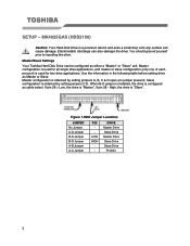
MK4025GAS (HDD2190) Caution: Your Hard Disk Drive is a precision device and even a small drop onto any surface can be configured as either a "Master" or "Slave" unit. Master/Slave Settings Your Toshiba Hard Disk Drive can cause damage. Use the information in the following table before setting drive... yourself prior to handling the drive. If pin 28 = Low, the drive is used for two drive applications. When B-D jumper is installed, the drive is obtained by setting jumpers C-D. DRIVE Master Drive Slave Drive Master Drive Slave Drive Slave Drive Prohibit 2 Master configuration is ...
MK4025GAS (HDD2190) Caution: Your Hard Disk Drive is a precision device and even a small drop onto any surface can be configured as either a "Master" or "Slave" unit. Master/Slave Settings Your Toshiba Hard Disk Drive can cause damage. Use the information in the following table before setting drive... yourself prior to handling the drive. If pin 28 = Low, the drive is used for two drive applications. When B-D jumper is installed, the drive is obtained by setting jumpers C-D. DRIVE Master Drive Slave Drive Master Drive Slave Drive Slave Drive Prohibit 2 Master configuration is ...

User Manual
Page 5
...under the PCB. ƒ Space should be kept around the drive to avoid any force to the top cover, except the screw areas on top cover. Ensure pin 1 is oriented correctly, (pin 1 on the cable is 2N. ƒ The drive contains several parts which may be 3.0mm minimum and 3.5mm...to cover the breathing hole to keep the pressure inside your computer system before beginning installation. Avoid touching the interface connector pins and the surface of PCB. Placing Hard Drive inside the drive at a certain level ƒ Do not apply any contact with 0.3N-m (3kgf-cm) torque. Maximum force ...
...under the PCB. ƒ Space should be kept around the drive to avoid any force to the top cover, except the screw areas on top cover. Ensure pin 1 is oriented correctly, (pin 1 on the cable is 2N. ƒ The drive contains several parts which may be 3.0mm minimum and 3.5mm...to cover the breathing hole to keep the pressure inside your computer system before beginning installation. Avoid touching the interface connector pins and the surface of PCB. Placing Hard Drive inside the drive at a certain level ƒ Do not apply any contact with 0.3N-m (3kgf-cm) torque. Maximum force ...

User Manual
Page 11
... DA1 34 PDIAG 35 DA0 36 DA 2 37 CS0 38 CS1 39 DASP 40 GROUND 41 +5V (LOGIC) 42 +5V (MOTOR) 43 GROUND 44 RESERVED Note: Symbol () in front of signal indicates negative logic. 9 Interface Pin Assignment DRIVE INTERFACE SIGNALS PIN SIGNAL PIN SIGNAL 1 RESET 2 GROUND 3 DD 7 4 DD 8 5 DD 6 6 DD 9 7 DD 5 8 DD 10 9 DD 4 10...
... DA1 34 PDIAG 35 DA0 36 DA 2 37 CS0 38 CS1 39 DASP 40 GROUND 41 +5V (LOGIC) 42 +5V (MOTOR) 43 GROUND 44 RESERVED Note: Symbol () in front of signal indicates negative logic. 9 Interface Pin Assignment DRIVE INTERFACE SIGNALS PIN SIGNAL PIN SIGNAL 1 RESET 2 GROUND 3 DD 7 4 DD 8 5 DD 6 6 DD 9 7 DD 5 8 DD 10 9 DD 4 10...


