
Operation Manual
Page 1
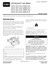
...Manual is supplied for information regarding the US Environmental Protection Agency (EPA) and the California Emission Control Regulation of the model and serial numbers on any forest-covered, brush-covered, or grass-covered land. This spark ignition system complies with a spark arrester muffler. 22in Recycler® Lawn Mower Model No. 20330... a hazard that may contact Toro directly at www.Toro.com for product and accessory information, help finding a dealer, or to avoid injury and product damage. Form No. 3360-854 Rev B Operator's Manual Introduction Read this product contains ...
...Manual is supplied for information regarding the US Environmental Protection Agency (EPA) and the California Emission Control Regulation of the model and serial numbers on any forest-covered, brush-covered, or grass-covered land. This spark ignition system complies with a spark arrester muffler. 22in Recycler® Lawn Mower Model No. 20330... a hazard that may contact Toro directly at www.Toro.com for product and accessory information, help finding a dealer, or to avoid injury and product damage. Form No. 3360-854 Rev B Operator's Manual Introduction Read this product contains ...
Operation Manual
Page 2
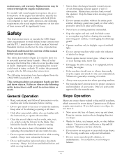
.... • Mow across the face of the American National Standards Institute in injury or death. Operation on the machine and in the manual(s) before you start to vibrate abnormally, stop the engine and check for walk-behind rotary lawn mowers and the B71.1 specifications of slopes; Uneven terrain could cause a slip and fall accidents...
.... • Mow across the face of the American National Standards Institute in injury or death. Operation on the machine and in the manual(s) before you start to vibrate abnormally, stop the engine and check for walk-behind rotary lawn mowers and the B71.1 specifications of slopes; Uneven terrain could cause a slip and fall accidents...
Operation Manual
Page 4
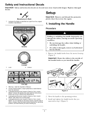
Indicates the blade is damaged, contact an Authorized Service Dealer. 1. Cutting/dismemberment hazard of hand or foot, mower blade-remove the ignition key and read the Operator's Manual. 2. Cutting/dismemberment hazard of the handle knobs as a part from the mower housing (Figure 3). Setup Manufacturer's Mark 1. Lock 112-8867 2. Important: Route the cables to the outside...
Indicates the blade is damaged, contact an Authorized Service Dealer. 1. Cutting/dismemberment hazard of hand or foot, mower blade-remove the ignition key and read the Operator's Manual. 2. Cutting/dismemberment hazard of the handle knobs as a part from the mower housing (Figure 3). Setup Manufacturer's Mark 1. Lock 112-8867 2. Important: Route the cables to the outside...
Operation Manual
Page 11
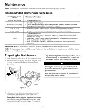
... Authorized Service Dealer (go to www.toro.com to find the nearest dealer) or at www.shoptoro.com. Always tip the mower onto its side, with a hand pump; Important: Refer to your engine operator's manual for any maintenance procedure. Refer to your engine operator's manual. • Refer to your engine operator's manual for additional maintenance procedures. Stop the...
... Authorized Service Dealer (go to www.toro.com to find the nearest dealer) or at www.shoptoro.com. Always tip the mower onto its side, with a hand pump; Important: Refer to your engine operator's manual for any maintenance procedure. Refer to your engine operator's manual. • Refer to your engine operator's manual for additional maintenance procedures. Stop the...
Operation Manual
Page 16
... Full Warranty for Residential Use (Limited Warranty for residential purposes*, if defective in Recycler® walk power mowers and their Toro Distributor (Dealer) to ensure that your product's engine in the Operator's Manual. Some states do not allow exclusions of purchase (sales receipt) to state. Cool temperature starts such as your proof of incidental or consequential...
... Full Warranty for Residential Use (Limited Warranty for residential purposes*, if defective in Recycler® walk power mowers and their Toro Distributor (Dealer) to ensure that your product's engine in the Operator's Manual. Some states do not allow exclusions of purchase (sales receipt) to state. Cool temperature starts such as your proof of incidental or consequential...
Service Manual
Page 6
Front Wheel Drive Models 3-9 22" TORO & LAWN-BOY REAR WHEEL DRIVE MODELS Transmission Removal & Belt Replacement 3-10 Rear Axle Disassembly 3-15 Transmission Disassembly 3-16 Transmission Assembly ... Tips 3-24 Transmission Installation Tips 3-25 THREE SPEED TRANSMISSION GEAR CASE ASSEMBLY 4-2 OPERATION Input System 4-3 ii WPM Drive Systems Manual SINGLE SPEED BEVEL GEAR TRANSMISSION 3-2 GENERAL INFORMATION 3-3 FRONT AXLE & TRANSMISSION ASSEMBLY 3-4 22" FRONT WHEEL DRIVE MODELS Remove Transmission 3-5 Transmission Disassembly 3-7 Transmission Assembly 3-7 Assembly Tips 3-8 ...
Front Wheel Drive Models 3-9 22" TORO & LAWN-BOY REAR WHEEL DRIVE MODELS Transmission Removal & Belt Replacement 3-10 Rear Axle Disassembly 3-15 Transmission Disassembly 3-16 Transmission Assembly ... Tips 3-24 Transmission Installation Tips 3-25 THREE SPEED TRANSMISSION GEAR CASE ASSEMBLY 4-2 OPERATION Input System 4-3 ii WPM Drive Systems Manual SINGLE SPEED BEVEL GEAR TRANSMISSION 3-2 GENERAL INFORMATION 3-3 FRONT AXLE & TRANSMISSION ASSEMBLY 3-4 22" FRONT WHEEL DRIVE MODELS Remove Transmission 3-5 Transmission Disassembly 3-7 Transmission Assembly 3-7 Assembly Tips 3-8 ...
Service Manual
Page 7
... System 5-9 WHEEL PINION SERVICE 5-9 BLADE BRAKE CLUTCH SYSTEMS (BBC), BLADE OVERRIDE SYSTEM (BOS), BLADE CLUTCH SYSTEM (BCS) BLADE BRAKE CLUTCH SYSTEM Description 6-2 BBC Clutch Option 6-2 Control Box Operation 6-2 Handle Controls 6-3 Control Box Disassembly 6-6 Control Box Assembly 6-7 TORO BBC SERVICE GUIDE 6-10 BLADE BRAKE CLUTCH ASSEMBLY (Toro Vacu Power/Lawn-Boy Medallion 6-11 TORO VACU POWER/LAWN-BOY...
... System 5-9 WHEEL PINION SERVICE 5-9 BLADE BRAKE CLUTCH SYSTEMS (BBC), BLADE OVERRIDE SYSTEM (BOS), BLADE CLUTCH SYSTEM (BCS) BLADE BRAKE CLUTCH SYSTEM Description 6-2 BBC Clutch Option 6-2 Control Box Operation 6-2 Handle Controls 6-3 Control Box Disassembly 6-6 Control Box Assembly 6-7 TORO BBC SERVICE GUIDE 6-10 BLADE BRAKE CLUTCH ASSEMBLY (Toro Vacu Power/Lawn-Boy Medallion 6-11 TORO VACU POWER/LAWN-BOY...
Service Manual
Page 8
...Boy Sens-a-Speed 7-9 Operation 7-9 Handle Disassembly, ...Toro Vacu Power/Lawn-Boy Medallion 7-15 Toro BBC Cable Adjustment (Recycler/Rear Bagger 7-16 Toro BOS Control 7-17 Toro...Toro 21" Front Wheel Drive 8-2 22" Front Wheel Drive 8-2 22" Rear Wheel Drive 8-2 21" Steel & Cast Deck Toro & Lawn-Boy Mowers Belt Replacement 8-2 21" Cast Deck Mowers with 3 Speed Transmission 8-2 21" Toro & Lawn-Boy Mowers with Blade Brake Clutch 8-3 21" Toro Mowers with Blade Override System & Lawn-Boy Mower with Blade Brake Clutch System 8-3 21" Lawn-Boy Insight Mowers 8-3 iv WPM Drive Systems Manual
...Boy Sens-a-Speed 7-9 Operation 7-9 Handle Disassembly, ...Toro Vacu Power/Lawn-Boy Medallion 7-15 Toro BBC Cable Adjustment (Recycler/Rear Bagger 7-16 Toro BOS Control 7-17 Toro...Toro 21" Front Wheel Drive 8-2 22" Front Wheel Drive 8-2 22" Rear Wheel Drive 8-2 21" Steel & Cast Deck Toro & Lawn-Boy Mowers Belt Replacement 8-2 21" Cast Deck Mowers with 3 Speed Transmission 8-2 21" Toro & Lawn-Boy Mowers with Blade Brake Clutch 8-3 21" Toro Mowers with Blade Override System & Lawn-Boy Mower with Blade Brake Clutch System 8-3 21" Lawn-Boy Insight Mowers 8-3 iv WPM Drive Systems Manual

Service Manual
Page 27
...Install the cover on its side (Fig. 020). Then secure the 4 self-tapping screws. One cable operates the engine kill switch and flywheel brake; Plug 3428-0166 6. Install worm shaft in the cover ...press it in place. WORM DRIVE TRANSMISSION 5. Press the bearing in until it is fully seated in the mower. A A B A. There are two control cables used with gear oil AFTER it is installed in the..., use tool P/N 27-0490 to align the cover and case. WPM Drive Systems Manual 1-9 Use a new gasket. Do not fully tighten them. 8. Tool P/N 27-0490 Fig 019 3428-0159 ...
...Install the cover on its side (Fig. 020). Then secure the 4 self-tapping screws. One cable operates the engine kill switch and flywheel brake; Plug 3428-0166 6. Install worm shaft in the cover ...press it in place. WORM DRIVE TRANSMISSION 5. Press the bearing in until it is fully seated in the mower. A A B A. There are two control cables used with gear oil AFTER it is installed in the..., use tool P/N 27-0490 to align the cover and case. WPM Drive Systems Manual 1-9 Use a new gasket. Do not fully tighten them. 8. Tool P/N 27-0490 Fig 019 3428-0159 ...
Service Manual
Page 47
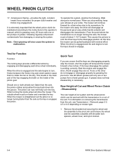
...mower on the wheel clutch see Section 5, Wheel Pinion Clutch. Identify right and left from under the housing (Fig. 057). Fig 057 MVC-482 3. Front Wheel Drive Models To replace the self-propelled drive belt, proceed as follows: 1. The wheel.... WPM Drive Systems Manual Fig 058 MVC-487 3-9 If the wheel pinions are reversed, the wheels will not drive. ...Belt Service - Slip the belt off the transmission pulley and push it towards the engine (Fig. 058). Remove the two screws securing the belt cover from the operator...
...mower on the wheel clutch see Section 5, Wheel Pinion Clutch. Identify right and left from under the housing (Fig. 057). Fig 057 MVC-482 3. Front Wheel Drive Models To replace the self-propelled drive belt, proceed as follows: 1. The wheel.... WPM Drive Systems Manual Fig 058 MVC-487 3-9 If the wheel pinions are reversed, the wheels will not drive. ...Belt Service - Slip the belt off the transmission pulley and push it towards the engine (Fig. 058). Remove the two screws securing the belt cover from the operator...

Service Manual
Page 56
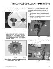
... not drive. Identify right and left side. SINGLE SPEED BEVEL GEAR TRANSMISSION 6. The letter L should face outward. The wheel pinion is marked with #2 molybendum disulfide grease or anti-seize compound before installing the pinion (Fig. 087). R Fig 088 MVC-474 Note: See ...Chapter 5 for right and left. On the right side, the R should face outward on Wheel Clutches. 3-18 WPM Drive Systems Manual Coat the axle, key, and spring with an R and L for more information on the left from the...
... not drive. Identify right and left side. SINGLE SPEED BEVEL GEAR TRANSMISSION 6. The letter L should face outward. The wheel pinion is marked with #2 molybendum disulfide grease or anti-seize compound before installing the pinion (Fig. 087). R Fig 088 MVC-474 Note: See ...Chapter 5 for right and left. On the right side, the R should face outward on Wheel Clutches. 3-18 WPM Drive Systems Manual Coat the axle, key, and spring with an R and L for more information on the left from the...
Service Manual
Page 64
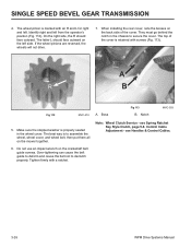
...& Control Cables. 3-26 WPM Drive Systems Manual The top of the cover. Note: Wheel Clutch Service - When installing the rear cover, note the bosses on the left from the operator's position (Fig. 112). They must go behind the notch in the wheel cover. Boss Fig 113 B. Identify right ...impact wrench on the mower together. 6. On the right side, the R should face outward on the back side of the cover is properly seated in the chassis to declutch properly. A R B Fig 112 MVC-474 A. The wheel pinion is to assemble the wheel, wheel cover, and wheel bolt, then put...
...& Control Cables. 3-26 WPM Drive Systems Manual The top of the cover. Note: Wheel Clutch Service - When installing the rear cover, note the bosses on the left from the operator's position (Fig. 112). They must go behind the notch in the wheel cover. Boss Fig 113 B. Identify right ...impact wrench on the mower together. 6. On the right side, the R should face outward on the back side of the cover is properly seated in the chassis to declutch properly. A R B Fig 112 MVC-474 A. The wheel pinion is to assemble the wheel, wheel cover, and wheel bolt, then put...

Service Manual
Page 67
... These gears are powdered metal and ride on a hexagonal shaft supported on top of gears - Gear sleeve E. THREE SPEED TRANSMISSION OPERATION Input System: Power is released, gravity pivots the transmission forward to loosen the belt. When the control bar is transferred from the engine to the transmission...the engine pulley (Fig. 115). The driven bevel gear turns the shaft so that all three gears on the output shaft. When the operator squeezes the control bar toward the handle, a control cable tilts the transmission backward and tensions the belt. Output shaft & gears 3428-...
... These gears are powdered metal and ride on a hexagonal shaft supported on top of gears - Gear sleeve E. THREE SPEED TRANSMISSION OPERATION Input System: Power is released, gravity pivots the transmission forward to loosen the belt. When the control bar is transferred from the engine to the transmission...the engine pulley (Fig. 115). The driven bevel gear turns the shaft so that all three gears on the output shaft. When the operator squeezes the control bar toward the handle, a control cable tilts the transmission backward and tensions the belt. Output shaft & gears 3428-...

Service Manual
Page 68
... bushings for two different engine speeds. Note: There are also three gears on the output shaft. Table 1 shows approximate speeds in gears for smooth operation and long wear (Fig. 117). Shift Collar Fig 117 C. Gear Selection System: Gear selection is determined by moving sliding shift keys in a sleeve... output shaft with a roll pin so the gear sleeve always rotates with the gear sleeve and the output shaft. Keys 3428-0065 The operator controls movement of the shift fork positions the shift collar and shift key. THREE SPEED TRANSMISSION There are no shift detents in or on...
... bushings for two different engine speeds. Note: There are also three gears on the output shaft. Table 1 shows approximate speeds in gears for smooth operation and long wear (Fig. 117). Shift Collar Fig 117 C. Gear Selection System: Gear selection is determined by moving sliding shift keys in a sleeve... output shaft with a roll pin so the gear sleeve always rotates with the gear sleeve and the output shaft. Keys 3428-0065 The operator controls movement of the shift fork positions the shift collar and shift key. THREE SPEED TRANSMISSION There are no shift detents in or on...

Service Manual
Page 70
...-tapping screws securing end caps to the transmission case. Slide the transmission to the right to "OPERATION" on page 5-3). 3. Pivot both rear wheels and wheel covers. 2. Remove the cover (Fig. 121). Fig 120 3428-0121 4-6 WPM Drive Systems Manual Disconnect shift and clutch cables. 5. Slide the pivot arm and spring arm off the pulley...
...-tapping screws securing end caps to the transmission case. Slide the transmission to the right to "OPERATION" on page 5-3). 3. Pivot both rear wheels and wheel covers. 2. Remove the cover (Fig. 121). Fig 120 3428-0121 4-6 WPM Drive Systems Manual Disconnect shift and clutch cables. 5. Slide the pivot arm and spring arm off the pulley...

Service Manual
Page 79
...low pull back forces similar to "free-wheel" when down . Keyed Thrust Washer - internal tab fits in the keyway of the output shaft to protect pivot arm from premature wear. 10. Allows the wheel... WPM Drive Systems Manual 5-3 provides support for the output shaft with the output shaft and protects outboard clutch components from the output shaft when the operator is necessary to ... to the wheels. 8. It is a left -hand and right-hand key. 15. Wheel pinion turning forward "wipes" key down . turns when the operator squeezes the handle to provide power to retain...
...low pull back forces similar to "free-wheel" when down . Keyed Thrust Washer - internal tab fits in the keyway of the output shaft to protect pivot arm from premature wear. 10. Allows the wheel... WPM Drive Systems Manual 5-3 provides support for the output shaft with the output shaft and protects outboard clutch components from the output shaft when the operator is necessary to ... to the wheels. 8. It is a left -hand and right-hand key. 15. Wheel pinion turning forward "wipes" key down . turns when the operator squeezes the handle to provide power to retain...
Service Manual
Page 80
...back down into the groove. If one or both engage they are disengaging properly, stop walking, keep your sides. When you are unsure that the wheel pinion clutch be serviced with minimal effort. As the mower rolls away, the drive will continue forward for a few inches. This causes the ...to the instructions in the main part of -Cut and Wheel Pinion Clutch - Rear Height-of the key engaging the teeth on the key. To operate this time the mower can now roll freely over the key. This results in the operator's manual, which is extremely important that the keys are ok....
...back down into the groove. If one or both engage they are disengaging properly, stop walking, keep your sides. When you are unsure that the wheel pinion clutch be serviced with minimal effort. As the mower rolls away, the drive will continue forward for a few inches. This causes the ...to the instructions in the main part of -Cut and Wheel Pinion Clutch - Rear Height-of the key engaging the teeth on the key. To operate this time the mower can now roll freely over the key. This results in the operator's manual, which is extremely important that the keys are ok....
Service Manual
Page 88
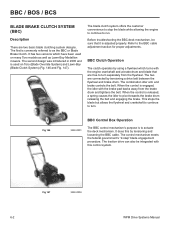
...64258;ywheel which have been used on many Toro models as well as the BBC or Blade Brake Clutch. When the control is commonly referred to as Lawn-Boy Medallion mowers. It does this control system. Fig 147 3428-0004 6-2 WPM Drive Systems Manual The first is released, a spring ... and loosening the BBC cable. It has two versions which turns with the brake pad backs away from the flywheel. BBC Clutch Operation The clutch operates by tensioning a drive belt between the flywheel and brake drum. BBC / BOS / BCS BLADE BRAKE CLUTCH SYSTEM (BBC) Description...
...64258;ywheel which have been used on many Toro models as well as the BBC or Blade Brake Clutch. When the control is commonly referred to as Lawn-Boy Medallion mowers. It does this control system. Fig 147 3428-0004 6-2 WPM Drive Systems Manual The first is released, a spring ... and loosening the BBC cable. It has two versions which turns with the brake pad backs away from the flywheel. BBC Clutch Operation The clutch operates by tensioning a drive belt between the flywheel and brake drum. BBC / BOS / BCS BLADE BRAKE CLUTCH SYSTEM (BBC) Description...
Service Manual
Page 89
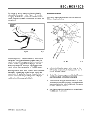
...-propel. b. On units without self-propel, the control bar can regulate the ground speed of self-propel models without affecting operation of the BBC system. Transfers operator inputs to position 3. WPM Drive Systems Manual 6-3 c. Traction Cable: engages the transmission by the number 1 in the Figure 148. Fig 148 fig 27 Notice that position...
...-propel. b. On units without self-propel, the control bar can regulate the ground speed of self-propel models without affecting operation of the BBC system. Transfers operator inputs to position 3. WPM Drive Systems Manual 6-3 c. Traction Cable: engages the transmission by the number 1 in the Figure 148. Fig 148 fig 27 Notice that position...

Service Manual
Page 90
... position when at rest. Buckling Spring: sole purpose is spring-loaded in a slot on the upper shoulder bolt when the control bar is operated. It rides in the counterclockwise direction by the torsion spring. Right Control Housing: serves as the control bar drops to the control arm by... cable is retained in Figure 150 the position of the roll pin. both the control hook and cable lever. Buckling spring 6-4 WPM Drive Systems Manual g. Movement is affixed solidly to "at the left end of its lowest or uppermost positions. j. Notice that supports it . It ...
... position when at rest. Buckling Spring: sole purpose is spring-loaded in a slot on the upper shoulder bolt when the control bar is operated. It rides in the counterclockwise direction by the torsion spring. Right Control Housing: serves as the control bar drops to the control arm by... cable is retained in Figure 150 the position of the roll pin. both the control hook and cable lever. Buckling spring 6-4 WPM Drive Systems Manual g. Movement is affixed solidly to "at the left end of its lowest or uppermost positions. j. Notice that supports it . It ...

