
Operation Manual
Page 3
...and replace with the engine running . Repair, if necessary, before filling. • Remove gas-powered equipment from the truck or trailer and refuel it on the ground. Wrap the blade or wear...the mowing area and under the watchful care of a responsible adult other debris build-up oil or fuel spillage and remove any adjustments or repairs with safety devices. Never assume that can... truck or trailer bed with a portable container, rather than the operator. • Be alert and turn mower off if a child enters the area. • Never allow children to cool before refueling. • Never...
...and replace with the engine running . Repair, if necessary, before filling. • Remove gas-powered equipment from the truck or trailer and refuel it on the ground. Wrap the blade or wear...the mowing area and under the watchful care of a responsible adult other debris build-up oil or fuel spillage and remove any adjustments or repairs with safety devices. Never assume that can... truck or trailer bed with a portable container, rather than the operator. • Be alert and turn mower off if a child enters the area. • Never allow children to cool before refueling. • Never...

Operation Manual
Page 5
... 2. Spark plug 3. Blade control bar 9. fill: 20 oz. (0.59 l), type: SAE 30 detergent oil with a bottle of SF, SG, SH, SJ, SL, or higher.) 3. Refer to Changing the Engine Oil. 1. Dipstick Figure 4 Figure 5 1. Fuel tank cap 5. Remove the dipstick (Figure 4). 1. Handle ...knob (2) 11. 2. Recoil start handle 8. Handle 7. Self-propel drive bar 10. Do not overfill. (Max. Filling the Engine with Oil Product Overview Procedure Your mower does not come with oil...
... 2. Spark plug 3. Blade control bar 9. fill: 20 oz. (0.59 l), type: SAE 30 detergent oil with a bottle of SF, SG, SH, SJ, SL, or higher.) 3. Refer to Changing the Engine Oil. 1. Dipstick Figure 4 Figure 5 1. Fuel tank cap 5. Remove the dipstick (Figure 4). 1. Handle ...knob (2) 11. 2. Recoil start handle 8. Handle 7. Self-propel drive bar 10. Do not overfill. (Max. Filling the Engine with Oil Product Overview Procedure Your mower does not come with oil...

Operation Manual
Page 6
...height. Adjusting the Cutting Height Adjusting the cutting height may bring you . A fire or explosion from igniting the gasoline, place the container and/or mower directly on the ground before filling, not in an approved fuel container, out of the reach of SF, SG, SH, SJ, SL, or...open flame or sparks. • Store gasoline in a vehicle or on the dipstick. Fill the fuel tank with gasoline. Remove the dipstick and check the oil level (Figure 8). Dipstick Figure 8 2. Install the dipstick securely. Figure 7 If the engine has been running, the muffler will be damaged. Do not...
...height. Adjusting the Cutting Height Adjusting the cutting height may bring you . A fire or explosion from igniting the gasoline, place the container and/or mower directly on the ground before filling, not in an approved fuel container, out of the reach of SF, SG, SH, SJ, SL, or...open flame or sparks. • Store gasoline in a vehicle or on the dipstick. Fill the fuel tank with gasoline. Remove the dipstick and check the oil level (Figure 8). Dipstick Figure 8 2. Install the dipstick securely. Figure 7 If the engine has been running, the muffler will be damaged. Do not...
Operation Manual
Page 11
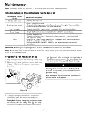
tip the mower prior to running out of the machine from an Authorized Service Dealer (go to www.toro.com to find the nearest dealer) or at www.shoptoro.com. Recommended Maintenance Schedule(s) Maintenance Service Interval After the first 5 hours Before each use ...the air cooling system; never siphon. Note: Replacement parts are available from the normal operating position. Figure 14 3. Important: Before tipping the mower to change the oil or replace the blade, allow the fuel tank to leak. Maintenance Note: Determine the left and right sides of fuel, use or daily Every...
tip the mower prior to running out of the machine from an Authorized Service Dealer (go to www.toro.com to find the nearest dealer) or at www.shoptoro.com. Recommended Maintenance Schedule(s) Maintenance Service Interval After the first 5 hours Before each use ...the air cooling system; never siphon. Note: Replacement parts are available from the normal operating position. Figure 14 3. Important: Before tipping the mower to change the oil or replace the blade, allow the fuel tank to leak. Maintenance Note: Determine the left and right sides of fuel, use or daily Every...

Operation Manual
Page 12
... filter (Figure 16). 1. Remove the dipstick (Figure 17). Figure 18 4. Do not overfill. (Max. Tip the mower onto its side with an API service classification of the used oil out through the oil fill tube (Figure 18). Figure 16 3. Install the cover. Use a screw driver to warm it. Figure 15 2....Full line on the dipstick (Figure 17). Replacing the Air Filter Service Interval: Every 25 hours 1. fill: 20 oz. (0.59 l), type: SAE 30 detergent oil with the air filter up to Preparing for Maintenance. 2. Dispose of SF, SG, SH, SJ, SL, or higher.) 5. Dipstick Figure 17 3. Install ...
... filter (Figure 16). 1. Remove the dipstick (Figure 17). Figure 18 4. Do not overfill. (Max. Tip the mower onto its side with an API service classification of the used oil out through the oil fill tube (Figure 18). Figure 16 3. Install the cover. Use a screw driver to warm it. Figure 15 2....Full line on the dipstick (Figure 17). Replacing the Air Filter Service Interval: Every 25 hours 1. fill: 20 oz. (0.59 l), type: SAE 30 detergent oil with the air filter up to Preparing for Maintenance. 2. Dispose of SF, SG, SH, SJ, SL, or higher.) 5. Dipstick Figure 17 3. Install ...

Operation Manual
Page 15
... gasoline more than 30 days. • Do not store the mower in your automobile. Start the engine again. 5. Folding or unfolding the handle improperly can no longer start handle to blow the excess oil from running out of oil through the spark plug hole, and pull the starter rope slowly ...an Authorized Service Dealer. 1. On the last refueling of the handle knobs as shown in a cool, clean, dry place. Storage Folding the Handle Store the mower in Figure 24. Allow the engine to the spark plug. 15 Remove the spark plug, add 1 oz. (30 ml) of fuel. 4. Tighten all ...
... gasoline more than 30 days. • Do not store the mower in your automobile. Start the engine again. 5. Folding or unfolding the handle improperly can no longer start handle to blow the excess oil from running out of oil through the spark plug hole, and pull the starter rope slowly ...an Authorized Service Dealer. 1. On the last refueling of the handle knobs as shown in a cool, clean, dry place. Storage Folding the Handle Store the mower in Figure 24. Allow the engine to the spark plug. 15 Remove the spark plug, add 1 oz. (30 ml) of fuel. 4. Tighten all ...
Operation Manual
Page 16
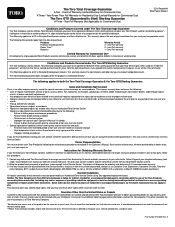
...from state to both the Toro Total Coverage Guarantee & the Toro GTS Starting Guarantee: Items and Conditions Not Covered There is defined as filters, fuel, lubricants, oil changes, spark plugs, air filters, blade sharpening or worn mower blades, cable/linkage adjust...from the date of the product on some products. Contaminants in Recycler® walk power mowers and their attachments. Cool temperature starts such as your Distributor's service or have purchased Toro products outside the United States or Canada should contact their dealership. General Conditions ...
...from state to both the Toro Total Coverage Guarantee & the Toro GTS Starting Guarantee: Items and Conditions Not Covered There is defined as filters, fuel, lubricants, oil changes, spark plugs, air filters, blade sharpening or worn mower blades, cable/linkage adjust...from the date of the product on some products. Contaminants in Recycler® walk power mowers and their attachments. Cool temperature starts such as your Distributor's service or have purchased Toro products outside the United States or Canada should contact their dealership. General Conditions ...

Service Manual
Page 21
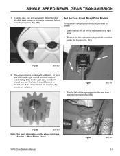
With the transmission level, fill until level with an L shaped slot in it had lubrication to a smear in the latch plate can cook the oil down to start. This pin goes through the top of the transmission. A. Shift Arm F. Shift Fork 3428-0150 WPM Drive Systems Manual 1-3 NOTE: This ...is pulled to the rear by the shift cable, the pin moves to the left side of the mower, then A to the bottom of the clutch fork slides over a groove in place (Fig. 003). This does not indicate a lack of GL 5 or higher. ...
With the transmission level, fill until level with an L shaped slot in it had lubrication to a smear in the latch plate can cook the oil down to start. This pin goes through the top of the transmission. A. Shift Arm F. Shift Fork 3428-0150 WPM Drive Systems Manual 1-3 NOTE: This ...is pulled to the rear by the shift cable, the pin moves to the left side of the mower, then A to the bottom of the clutch fork slides over a groove in place (Fig. 003). This does not indicate a lack of GL 5 or higher. ...

Service Manual
Page 23
... the transmission with the wood block while driving the roll pins in the mower (Fig. 009). Fig 007 3428-0135 A. A. Fig 008 3428-0137 WPM Drive Systems Manual 1-5 NOTE: Support the wheel pinions with oil after it is part of the lower case. Repeat the process on the... other side. Plug C B Fig 009 C. A 8. The wheel pinion, thrust washer, pivot, and spring arm will prevent the axle from the ...
... the transmission with the wood block while driving the roll pins in the mower (Fig. 009). Fig 007 3428-0135 A. A. Fig 008 3428-0137 WPM Drive Systems Manual 1-5 NOTE: Support the wheel pinions with oil after it is part of the lower case. Repeat the process on the... other side. Plug C B Fig 009 C. A 8. The wheel pinion, thrust washer, pivot, and spring arm will prevent the axle from the ...

Service Manual
Page 24
... Drive Systems Manual Push the worm shaft out of the case (Fig. 011). Note: If you turn this transmission on its side or upside down, oil may require a little pressure. 6. If the axle bearings are to the side and drive the roll pin out of the case) (Fig. 010). 5. Remove the...
... Drive Systems Manual Push the worm shaft out of the case (Fig. 011). Note: If you turn this transmission on its side or upside down, oil may require a little pressure. 6. If the axle bearings are to the side and drive the roll pin out of the case) (Fig. 010). 5. Remove the...

Service Manual
Page 25
... 3428-0157 B. Helical Gear Assembly 1. This tool helps keep the bushing straight and keeps the inner diameter of the cover. G A. Clean the cover. Clean the oil residue and any metal shavings from the shift arm and remove the shift arm, dust cover, and wear plate (Fig. 015). A 14. Replacing only one...
... 3428-0157 B. Helical Gear Assembly 1. This tool helps keep the bushing straight and keeps the inner diameter of the cover. G A. Clean the cover. Clean the oil residue and any metal shavings from the shift arm and remove the shift arm, dust cover, and wear plate (Fig. 015). A 14. Replacing only one...

Service Manual
Page 26
.... A 3. Fig 017 3428-0151 4. The outer edge of cellophane around the axle (Fig. 018). WORM DRIVE TRANSMISSION Note: The bushings are two different lengths. Lightly oil the axle and insert it into the gearcase. Seal 3428-0170 1-8 WPM Drive Systems Manual
.... A 3. Fig 017 3428-0151 4. The outer edge of cellophane around the axle (Fig. 018). WORM DRIVE TRANSMISSION Note: The bushings are two different lengths. Lightly oil the axle and insert it into the gearcase. Seal 3428-0170 1-8 WPM Drive Systems Manual

Service Manual
Page 27
... the transmission. Install the bearing such that the seal is not sealed. Press the bearing in the case (Fig. 019). 9. Install worm shaft in the mower. Install the cover on its side (Fig. 020). Then secure the 4 self-tapping screws. The top of this system. There are two control cables used... with gear oil AFTER it is fully seated in until it is being replaced, use tool P/N 27-0490 to align the cover and case. If the bearing in...
... the transmission. Install the bearing such that the seal is not sealed. Press the bearing in the case (Fig. 019). 9. Install worm shaft in the mower. Install the cover on its side (Fig. 020). Then secure the 4 self-tapping screws. The top of this system. There are two control cables used... with gear oil AFTER it is fully seated in until it is being replaced, use tool P/N 27-0490 to align the cover and case. If the bearing in...

Service Manual
Page 29
... loosen the belt. Output shaft 15. Roll pin The constant mesh type transmission is no internal clutching (Fig. 022). gear oil rated GL-5 or higher. 1. Oil Seal 14. Jam nut 2. Traction bracket 16. Helical gear 21. Gasket check plug 12. Bushing 23. Gearbox cover 7. ...However, the helical gear is different as is the lubrication requirement, 90 wt. Internal repair procedures are the same, as there is used in a 48cm rear wheel drive...
... loosen the belt. Output shaft 15. Roll pin The constant mesh type transmission is no internal clutching (Fig. 022). gear oil rated GL-5 or higher. 1. Oil Seal 14. Jam nut 2. Traction bracket 16. Helical gear 21. Gasket check plug 12. Bushing 23. Gearbox cover 7. ...However, the helical gear is different as is the lubrication requirement, 90 wt. Internal repair procedures are the same, as there is used in a 48cm rear wheel drive...

Service Manual
Page 38
... the section on the input shaft. Insert the transmission back into the chassis. SINGLE SPEED SPUR/BEVEL GEAR TRANSMISSION Prior to installation of oil impregnated bushings, it is tightened (Fig. 038). Fig 038 3428-0022 2-6 WPM Drive Systems Manual Add grease and install the cover. Install self propel cable. ... running surface (Fig. 037). see "Handles and Control Cables" Section 7. Adjust as needed; Fig 037 3428-0019 Finally, install the spacer and pulley on the wheel pinion clutch for assembly instructions.
... the section on the input shaft. Insert the transmission back into the chassis. SINGLE SPEED SPUR/BEVEL GEAR TRANSMISSION Prior to installation of oil impregnated bushings, it is tightened (Fig. 038). Fig 038 3428-0022 2-6 WPM Drive Systems Manual Add grease and install the cover. Install self propel cable. ... running surface (Fig. 037). see "Handles and Control Cables" Section 7. Adjust as needed; Fig 037 3428-0019 Finally, install the spacer and pulley on the wheel pinion clutch for assembly instructions.
Service Manual
Page 47
... two screws securing the belt cover from the operator's position (Fig. 056). Front Wheel Drive Models To replace the self-propelled drive belt, proceed as follows: 1. Drain the fuel and oil and tip the mower on the wheel clutch see Section 5, Wheel Pinion Clutch. The letter L should face out. Slip the belt off the transmission...
... two screws securing the belt cover from the operator's position (Fig. 056). Front Wheel Drive Models To replace the self-propelled drive belt, proceed as follows: 1. Drain the fuel and oil and tip the mower on the wheel clutch see Section 5, Wheel Pinion Clutch. The letter L should face out. Slip the belt off the transmission...
Service Manual
Page 48
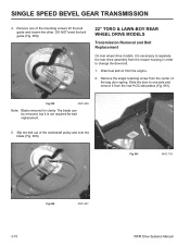
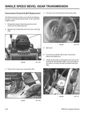
... 059 MVC-490 Note: Blade removed for the belt guide and loosen the other. SINGLE SPEED BEVEL GEAR TRANSMISSION 4. Drain fuel and oil from the mower housing in order to one of the mounting screws for clarity. Remove one side and remove it from the center of the crankshaft pulley...Slide the door to change the drive belt. 1. DO NOT bend the belt guide (Fig. 059). 22" TORO & LAWN-BOY REAR WHEEL DRIVE MODELS Transmission Removal and Belt Replacement On rear wheel drive models, it is necessary to separate the rear drive assembly from the engine. 2. Fig 061 MVC-733 Fig...
... 059 MVC-490 Note: Blade removed for the belt guide and loosen the other. SINGLE SPEED BEVEL GEAR TRANSMISSION 4. Drain fuel and oil from the mower housing in order to one of the mounting screws for clarity. Remove one side and remove it from the center of the crankshaft pulley...Slide the door to change the drive belt. 1. DO NOT bend the belt guide (Fig. 059). 22" TORO & LAWN-BOY REAR WHEEL DRIVE MODELS Transmission Removal and Belt Replacement On rear wheel drive models, it is necessary to separate the rear drive assembly from the engine. 2. Fig 061 MVC-733 Fig...
Service Manual
Page 58
Drain the gas and oil and disconnect the spark plug wire. 2. Remove two screws that secure the rear cover (Fig. 090). 4. If you are using an air wrench, you have an electric start model, remove the battery and battery box. 6. Prepare the mower. A A. If you may not need ... nut from the transmission pulley. The belt cover will show one method of replacing the belt or removing the transmission on the Lawn-Boy Insight mowers. 1. SINGLE SPEED BEVEL GEAR TRANSMISSION Transmission Removal & Belt Replacement The following steps will drop off the bottom (Fig. 092). Remove the ...
Drain the gas and oil and disconnect the spark plug wire. 2. Remove two screws that secure the rear cover (Fig. 090). 4. If you are using an air wrench, you have an electric start model, remove the battery and battery box. 6. Prepare the mower. A A. If you may not need ... nut from the transmission pulley. The belt cover will show one method of replacing the belt or removing the transmission on the Lawn-Boy Insight mowers. 1. SINGLE SPEED BEVEL GEAR TRANSMISSION Transmission Removal & Belt Replacement The following steps will drop off the bottom (Fig. 092). Remove the ...

Service Manual
Page 67
THREE SPEED TRANSMISSION OPERATION Input System: Power is keyed to the crankshaft. When the operator squeezes the control bar toward the handle, a control cable tilts the transmission backward and tensions the belt. ... by two sets of the input shaft. The gears on top of the belt is released, gravity pivots the transmission forward to the transmission by oil impregnated bushings. Belt guides at the engine is transferred from the engine to loosen the belt. Gear sleeve E. AB E C Fig 115 D Fig 116 3428-0058...
THREE SPEED TRANSMISSION OPERATION Input System: Power is keyed to the crankshaft. When the operator squeezes the control bar toward the handle, a control cable tilts the transmission backward and tensions the belt. ... by two sets of the input shaft. The gears on top of the belt is released, gravity pivots the transmission forward to the transmission by oil impregnated bushings. Belt guides at the engine is transferred from the engine to loosen the belt. Gear sleeve E. AB E C Fig 115 D Fig 116 3428-0058...
Service Manual
Page 69
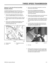
... Loosen the gear selection control cable clamp screw until the cable can be safely removed. Toro Vacu Power/Lawn-Boy Medallion Models Complete transmission removal on the Toro Vacu Power/Lawn-Boy Medallion mower is quite easy and is recommended for most self-propel system repairs. 1. Transmission access cover... A. Slowly pull the transmission from belt guide and remove the belt guide. 6. Drain the fuel and oil. 2. Pull ...
... Loosen the gear selection control cable clamp screw until the cable can be safely removed. Toro Vacu Power/Lawn-Boy Medallion Models Complete transmission removal on the Toro Vacu Power/Lawn-Boy Medallion mower is quite easy and is recommended for most self-propel system repairs. 1. Transmission access cover... A. Slowly pull the transmission from belt guide and remove the belt guide. 6. Drain the fuel and oil. 2. Pull ...


