Installation Instructions
Page 2
Huntington Beach, CA 92649 Questions? 1-800-735-4328 www.thermador.com We look forward to hearing from you! Table of Contents Safety Instructions 1 Important Installation Information 2 Step 1: Ventilation Requirements 2 Step 2: Cabinet Preparation 4...the Range 8 Step 4: Installing Anti-Tip Device 9 Step 5: Gas Requirements and Hookup 11 Step 6: Electrical Requirements, Connection & Grounding 12 Step 7: Backguard Installation 13 Step 8: Door Removal and Reinstallation 14 Step 9: Placing and Leveling the Range 15 Step 10: Burner Test and Adjustment 17 Installer Checklist 18 To Clean...
Huntington Beach, CA 92649 Questions? 1-800-735-4328 www.thermador.com We look forward to hearing from you! Table of Contents Safety Instructions 1 Important Installation Information 2 Step 1: Ventilation Requirements 2 Step 2: Cabinet Preparation 4...the Range 8 Step 4: Installing Anti-Tip Device 9 Step 5: Gas Requirements and Hookup 11 Step 6: Electrical Requirements, Connection & Grounding 12 Step 7: Backguard Installation 13 Step 8: Door Removal and Reinstallation 14 Step 9: Placing and Leveling the Range 15 Step 10: Burner Test and Adjustment 17 Installer Checklist 18 To Clean...

Installation Instructions
Page 6
Do not obstruct the flow of the hood is 13" (330 mm). A 36-inch minimum clearance is less than a 12" ... there is required between combustible material Δ and the back edge of the range above the cooking surface, a Thermador Low Back or Pot and Pan Shelf must be installed. (See Figure 2). When clearance to combustible material Δ...024 inch (0.6 mm) aluminum, or 0.020 inch (0.5 mm) thick copper. Note: The maximum depth of over 12", a Thermador Flush Island Trim may be used when the bottom of the wood or metal cabinet is installed beside a combustible side wall. &#...
Do not obstruct the flow of the hood is 13" (330 mm). A 36-inch minimum clearance is less than a 12" ... there is required between combustible material Δ and the back edge of the range above the cooking surface, a Thermador Low Back or Pot and Pan Shelf must be installed. (See Figure 2). When clearance to combustible material Δ...024 inch (0.6 mm) aluminum, or 0.020 inch (0.5 mm) thick copper. Note: The maximum depth of over 12", a Thermador Flush Island Trim may be used when the bottom of the wood or metal cabinet is installed beside a combustible side wall. &#...

Installation Instructions
Page 7
... Gas Code" (ANSI Z223.1, Current Edition).*The range height is adjustable. The level of Combustible Material 30" Range - 30" 36" Range - 36" 48" Range - 48" 13" Max. } Cabinet Depth Range width 30", 36" or 48" 5" Min. For Electrical and Gas Supply Zone, see Figure 3A. Figure 1: Cabinet Clearances English 5 For 30...
... Gas Code" (ANSI Z223.1, Current Edition).*The range height is adjustable. The level of Combustible Material 30" Range - 30" 36" Range - 36" 48" Range - 48" 13" Max. } Cabinet Depth Range width 30", 36" or 48" 5" Min. For Electrical and Gas Supply Zone, see Figure 3A. Figure 1: Cabinet Clearances English 5 For 30...

Installation Instructions
Page 15
... 120 VAC 120 VAC 10 Amps 10 Amps 20 Amps 20 Amps 60 Hz. 60 Hz. 60 Hz. 60 Hz. Figure 11: Backguard Installation English 13 Front of the range for easy reference. In the absence of local codes and ordinances, the power supply connection shall be attached before sliding the...
... 120 VAC 120 VAC 10 Amps 10 Amps 20 Amps 20 Amps 60 Hz. 60 Hz. 60 Hz. 60 Hz. Figure 11: Backguard Installation English 13 Front of the range for easy reference. In the absence of local codes and ordinances, the power supply connection shall be attached before sliding the...

Installation Instructions
Page 16
CAUTION The Pot and Pan Shelf can melt • flammable items • a total load over 30 pounds (13.6kg) Range Width 30" 36" 48" Chart C: Backguard Kit Model Numbers 6" Std. Without the weight of the door, the powerful springs will snap the hinges ...
CAUTION The Pot and Pan Shelf can melt • flammable items • a total load over 30 pounds (13.6kg) Range Width 30" 36" 48" Chart C: Backguard Kit Model Numbers 6" Std. Without the weight of the door, the powerful springs will snap the hinges ...
Installation Instructions
Page 19
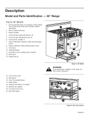
...been removed earlier. Test Oven Burners Remove the oven bottom cover. Test Flame: Low Setting. If any burners do not improve, call Thermador. After adjustment, retest. Test Bake Burner Ignition Set the oven to the XLO range. Step 10: Burner Test and Adjustment Install any.... Push in and turn counterclockwise to the electrical power supply. After 30-75 seconds, the burner will produce a clicking sound. See Figure 13 for LP Gas Test Burner Ignition. This is Properly Adjusted: • There should light within four (4) seconds. Select a rangetop burner knob...
...been removed earlier. Test Oven Burners Remove the oven bottom cover. Test Flame: Low Setting. If any burners do not improve, call Thermador. After adjustment, retest. Test Bake Burner Ignition Set the oven to the XLO range. Step 10: Burner Test and Adjustment Install any.... Push in and turn counterclockwise to the electrical power supply. After 30-75 seconds, the burner will produce a clicking sound. See Figure 13 for LP Gas Test Burner Ignition. This is Properly Adjusted: • There should light within four (4) seconds. Select a rangetop burner knob...
User Manual
Page 11
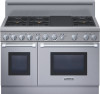
... Burner (hidden) 20. Electric Griddle 4. Oven Temperature Selectors, Main and Secondary Ovens 8. Range Feet (4) 1 2 2 2 3 4 5 8 7786 5 9 10 11 12 13 14. Convection Fan Cover 21. Oven Door 10. Broil Burner 16. Control Knob, Griddle (1) 7. Broil Glow Igniter Figure 4: 48" Model WARNING: To provide proper ventilation ...
... Burner (hidden) 20. Electric Griddle 4. Oven Temperature Selectors, Main and Secondary Ovens 8. Range Feet (4) 1 2 2 2 3 4 5 8 7786 5 9 10 11 12 13 14. Convection Fan Cover 21. Oven Door 10. Broil Burner 16. Control Knob, Griddle (1) 7. Broil Glow Igniter Figure 4: 48" Model WARNING: To provide proper ventilation ...

User Manual
Page 15
... by-products, do not touch burner caps or grates while hot. Figure 14 : Correct Burner Cap Placement Figure 15 : Incorrect Burner Cap Placement English 13 CAUTION: Do not touch the burners when the igniters are too high. • Flames shoot out of burners. • Burners do not ignite. ...• Burner flames light unevenly. • Burner emits gas odor. Burner Cap Ports Figure 13: Star® Burner Components Burner Cap Placement The burner caps must be properly placed on page 34. Turn the cooktop off and allow the burners...
... by-products, do not touch burner caps or grates while hot. Figure 14 : Correct Burner Cap Placement Figure 15 : Incorrect Burner Cap Placement English 13 CAUTION: Do not touch the burners when the igniters are too high. • Flames shoot out of burners. • Burners do not ignite. ...• Burner flames light unevenly. • Burner emits gas odor. Burner Cap Ports Figure 13: Star® Burner Components Burner Cap Placement The burner caps must be properly placed on page 34. Turn the cooktop off and allow the burners...