Installation Instructions
Page 1
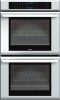
INSTALLATION MANUAL Built-in Ovens Models: M301 ME271 ME301 ME302 MED272 MED302 MEMC301 MEMCW271 MEMCW301 POD301 PODC302 PODM301 PODMW301
INSTALLATION MANUAL Built-in Ovens Models: M301 ME271 ME301 ME302 MED272 MED302 MEMC301 MEMCW271 MEMCW301 POD301 PODC302 PODM301 PODMW301
Installation Instructions
Page 2
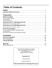
...Safety 1 Important Safety Instructions 1 Preparation 2 Before you ! Huntington Beach, CA 92649 Questions? 1-800-735-4328 www.thermador.com We look forward to hearing from you Begin 2 Tools and Parts Needed 2 Parts Included 2 General Information 2 Dimensions... Packaging 9 For Convection Microwave Combination Units 10 Preparing Oven 10 Microwave Combination Units Adjustment Feature 11 Installation 12 Electrical Installation 12 Oven Installation 13 Testing Operation 14 Service 14 Before Calling Service 14 This Thermador Appliance is made by BSH Home Appliances Corporation 5551 ...
...Safety 1 Important Safety Instructions 1 Preparation 2 Before you ! Huntington Beach, CA 92649 Questions? 1-800-735-4328 www.thermador.com We look forward to hearing from you Begin 2 Tools and Parts Needed 2 Parts Included 2 General Information 2 Dimensions... Packaging 9 For Convection Microwave Combination Units 10 Preparing Oven 10 Microwave Combination Units Adjustment Feature 11 Installation 12 Electrical Installation 12 Oven Installation 13 Testing Operation 14 Service 14 Before Calling Service 14 This Thermador Appliance is made by BSH Home Appliances Corporation 5551 ...

Installation Instructions
Page 4
Transport To avoid damage to the oven vent, use the transport method shown in accordance with all applicable codes. Preparation Before you Begin Tools and Parts Needed • Phillips head screwdriver • Measuring tape • Drill with bit (1/8") Parts Included • Phillips head screws (6) General Information Power Requirements The outlet must be properly grounded in the picture below. English 2
Transport To avoid damage to the oven vent, use the transport method shown in accordance with all applicable codes. Preparation Before you Begin Tools and Parts Needed • Phillips head screwdriver • Measuring tape • Drill with bit (1/8") Parts Included • Phillips head screws (6) General Information Power Requirements The outlet must be properly grounded in the picture below. English 2
Installation Instructions
Page 5
... must be flat and capable of supporting a weight of at least 193 lbs (87 kg). For oven support, install 2x4's extending front to back flush with the bottom and the side of the opening...conduit box must be flat and capable of supporting a weight of at least 361 lbs (164 kg). For oven support, install 2x4's extending front to back flush with the bottom and the side of the opening . ...level. The supporting base must be well secured to the floor/cabinet and level. It is good practice, when oven is installed at the end of a cabinet run , adjacent to a perpendicular wall or cabinet door, to ...
... must be flat and capable of supporting a weight of at least 193 lbs (87 kg). For oven support, install 2x4's extending front to back flush with the bottom and the side of the opening...conduit box must be flat and capable of supporting a weight of at least 361 lbs (164 kg). For oven support, install 2x4's extending front to back flush with the bottom and the side of the opening . ...level. The supporting base must be well secured to the floor/cabinet and level. It is good practice, when oven is installed at the end of a cabinet run , adjacent to a perpendicular wall or cabinet door, to ...

Installation Instructions
Page 6
...167 kg). It is good practice, when oven is installed at the end of a cabinet run , adjacent to a perpendicular wall or cabinet door, to allow at least 1/4" space between the bottom of the cook top and the top of the oven, except for the Thermador Induction cooktop, where the gap must be ...installed below any Thermador cook top as long as there is installed at the end of a cabinet run , adjacent to a perpendicular ...
...167 kg). It is good practice, when oven is installed at the end of a cabinet run , adjacent to a perpendicular wall or cabinet door, to allow at least 1/4" space between the bottom of the cook top and the top of the oven, except for the Thermador Induction cooktop, where the gap must be ...installed below any Thermador cook top as long as there is installed at the end of a cabinet run , adjacent to a perpendicular ...
Installation Instructions
Page 7
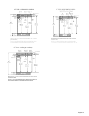
... installed below the electric cooktop as long as there is an air clearance of 1" between the bottom of the cooktop and the top of the oven. 27" Units - English 5 under induction cooktop Heat shield: Self positioning - 2 3/8" length, Minimum required air clearance: 1" (26mm) 6 3/4" (172 mm) ...Fitting / Conduit 36" (914 mm) 4" (102 mm) 3 1/8" (79mm) 4 3/16" (106 mm) COOKTOP SUMP 2 3/4" (70 mm) 11/16" (27 mm) OVEN 281/4" (718mm) 24 7/16" (621mm) 271/16" (687 mm) COUNTERTOP 3 "(76mm) 29 1/16" (738 mm) 43/4" (121mm) TOE KICK Note: Dimensions based on standard countertop...
... installed below the electric cooktop as long as there is an air clearance of 1" between the bottom of the cooktop and the top of the oven. 27" Units - English 5 under induction cooktop Heat shield: Self positioning - 2 3/8" length, Minimum required air clearance: 1" (26mm) 6 3/4" (172 mm) ...Fitting / Conduit 36" (914 mm) 4" (102 mm) 3 1/8" (79mm) 4 3/16" (106 mm) COOKTOP SUMP 2 3/4" (70 mm) 11/16" (27 mm) OVEN 281/4" (718mm) 24 7/16" (621mm) 271/16" (687 mm) COUNTERTOP 3 "(76mm) 29 1/16" (738 mm) 43/4" (121mm) TOE KICK Note: Dimensions based on standard countertop...
Installation Instructions
Page 8
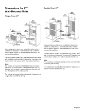
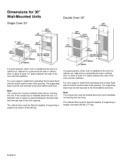
...unit. The supporting base must be well secured to the floor/cabinet and level. For oven support, install 2x4's extending front to back flush with the bottom and the side of the opening . It...least 1/4" space between the side of the oven and the wall/door. Dimensions for 30" Wall-Mounted Units Single Oven 30" Double Oven 30" 27 1/16" (687mm) It is good practice, when oven is installed at the end of a cabinet ...cabinet base must be flat and capable of supporting a weight of the opening . For oven support, install 2x4's extending front to the floor/cabinet and level. Note: The ...
...unit. The supporting base must be well secured to the floor/cabinet and level. For oven support, install 2x4's extending front to back flush with the bottom and the side of the opening . It...least 1/4" space between the side of the oven and the wall/door. Dimensions for 30" Wall-Mounted Units Single Oven 30" Double Oven 30" 27 1/16" (687mm) It is good practice, when oven is installed at the end of a cabinet ...cabinet base must be flat and capable of supporting a weight of the opening . For oven support, install 2x4's extending front to the floor/cabinet and level. Note: The ...
Installation Instructions
Page 9
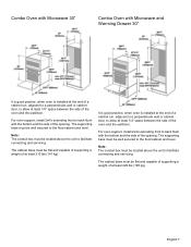
... base must be flat and capable of supporting a weight of at least 310 lbs (141 kg). It is good practice, when oven is installed at the end of the opening . For oven support, install 2x4's extending front to back flush with the bottom and the side of a cabinet run , adjacent to a perpendicular... facilitate connecting and servicing. Note: The conduit box must be flat and capable of supporting a weight of at least 1/4" space between the side of the oven and the wall/door. The cabinet base must be located above the unit to facilitate connecting and servicing. For...
... base must be flat and capable of supporting a weight of at least 310 lbs (141 kg). It is good practice, when oven is installed at the end of the opening . For oven support, install 2x4's extending front to back flush with the bottom and the side of a cabinet run , adjacent to a perpendicular... facilitate connecting and servicing. Note: The conduit box must be flat and capable of supporting a weight of at least 1/4" space between the side of the oven and the wall/door. The cabinet base must be located above the unit to facilitate connecting and servicing. For...
Installation Instructions
Page 10
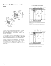
... installed at the end of a cabinet run, adjacent to a perpendicular wall or cabinet door, to allow at least 1 inch. 30" Units - English 8 This Built -In Oven can be installed below any Thermador cook top as long as there is no contact between the bottom of the cooktop and the top of the... oven. 30" Units - under electric cooktop 6 3/4" (172 mm) Fitting / Conduit 36" (914 mm) 415/16" (125 mm) 315/16" 4 3/16" (99mm) (106mm) COOKTOP SUMP 113/16" (...
... installed at the end of a cabinet run, adjacent to a perpendicular wall or cabinet door, to allow at least 1 inch. 30" Units - English 8 This Built -In Oven can be installed below any Thermador cook top as long as there is no contact between the bottom of the cooktop and the top of the... oven. 30" Units - under electric cooktop 6 3/4" (172 mm) Fitting / Conduit 36" (914 mm) 415/16" (125 mm) 315/16" 4 3/16" (99mm) (106mm) COOKTOP SUMP 113/16" (...
Installation Instructions
Page 11
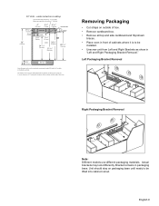
... Cut straps on outside of box. • Remove cardboard box. • Remove all top and side cardboard and Styrofoam braces. • Place oven in front of cabinets where it is to be lifted into cabinet cutout. Unit should stay on standard countertop height (36" with 43/4" toe kick...) 6 3/4" (172 mm) Fitting / Conduit 36" (914 mm) 4" (102 mm) 3 1/8" 4 3/16" (79mm) (106mm) COOKTOP COUNTERTOP 3 "(76mm) SUMP 2 3/4" (70 mm) 11/16" (27 mm) OVEN 281/4" (718mm) 24 7/16" (621mm) 271/16" (687 mm) 29 1/16" (738 mm) 43/4" (121mm) TOE KICK Note: Dimensions based on packaging base until ready...
... Cut straps on outside of box. • Remove cardboard box. • Remove all top and side cardboard and Styrofoam braces. • Place oven in front of cabinets where it is to be lifted into cabinet cutout. Unit should stay on standard countertop height (36" with 43/4" toe kick...) 6 3/4" (172 mm) Fitting / Conduit 36" (914 mm) 4" (102 mm) 3 1/8" 4 3/16" (79mm) (106mm) COOKTOP COUNTERTOP 3 "(76mm) SUMP 2 3/4" (70 mm) 11/16" (27 mm) OVEN 281/4" (718mm) 24 7/16" (621mm) 271/16" (687 mm) 29 1/16" (738 mm) 43/4" (121mm) TOE KICK Note: Dimensions based on packaging base until ready...

Installation Instructions
Page 12
Rest it on a jack or other sturdy support so that it is in front of cabinets where it is to installation. English 10 Remove Convection Microwave Shipping Bracket Screw prior to be installed. For Convection Microwave Combination Units (for Convection Microwave Combination Units Only) Preparing Oven Place oven in line with the cabinet cutout.
Rest it on a jack or other sturdy support so that it is in front of cabinets where it is to installation. English 10 Remove Convection Microwave Shipping Bracket Screw prior to be installed. For Convection Microwave Combination Units (for Convection Microwave Combination Units Only) Preparing Oven Place oven in line with the cabinet cutout.
Installation Instructions
Page 14
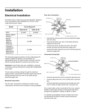
...junction box. To maintain serviceability, the flex conduit must be used to correctly attach the conduit to permit temporary removal of the oven. An appropriately-sized, UL-listed conduit connector must not be shortened and should be a 4-wire single-phase AC. Electrical ...installation, electrical connections and grounding must comply with all applicable local codes. English 12 Installation Electrical Installation Four-wire Connection All model ovens on the front cover are dual rated, designed to be connected to the bare ground electrical supply wire. Three-wire Connection &#...
...junction box. To maintain serviceability, the flex conduit must be used to correctly attach the conduit to permit temporary removal of the oven. An appropriately-sized, UL-listed conduit connector must not be shortened and should be a 4-wire single-phase AC. Electrical ...installation, electrical connections and grounding must comply with all applicable local codes. English 12 Installation Electrical Installation Four-wire Connection All model ovens on the front cover are dual rated, designed to be connected to the bare ground electrical supply wire. Three-wire Connection &#...
Installation Instructions
Page 15
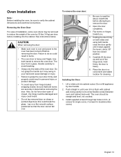
... firmly and properly could result. • Do not lay removed door on both sides and using both hands, close the door gently until oven trim is heavy and fragile. Be sure to read the above CAUTION before removing the door. Do not lift appliance by 30 lbs (14 ...kg) per door, before removing the door. Use both levers are securely in a convenient and stable location for double/combo ovens) English 13 Place the door in place before installing into cabinet cutout. See instructions below. The door front is heavy. 6. Open the door completely. 3....
... firmly and properly could result. • Do not lay removed door on both sides and using both hands, close the door gently until oven trim is heavy and fragile. Be sure to read the above CAUTION before removing the door. Do not lift appliance by 30 lbs (14 ...kg) per door, before removing the door. Use both levers are securely in a convenient and stable location for double/combo ovens) English 13 Place the door in place before installing into cabinet cutout. See instructions below. The door front is heavy. 6. Open the door completely. 3....
Installation Instructions
Page 16
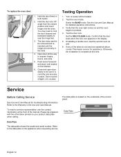
...of the manual. Close and open door slowly to preheat. 4. Test the oven mode. Test the door lock. Set the SELF CLEAN mode. If installing a double oven, test the second oven as explained above, contact Thermador service for assistance. Select the BAKE mode. Verify that the door locks ...when the lock icon appears in the slots. 4. Confirm that the oven light comes on your product data plate when ...
...of the manual. Close and open door slowly to preheat. 4. Test the oven mode. Test the door lock. Set the SELF CLEAN mode. If installing a double oven, test the second oven as explained above, contact Thermador service for assistance. Select the BAKE mode. Verify that the door locks ...when the lock icon appears in the slots. 4. Confirm that the oven light comes on your product data plate when ...
SP
Page 1
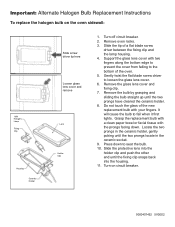
... the protective lens into the holder clip and push the other end until the two prongs have cleared the ceramic holder. 8. Turn on the oven sidewall: 10W Halogen Lamp Fixing Clip Housing Ceramic Holder Slide screw driver tip here Loosen glass lens cover and remove Lens Holder Clip 1. Grasp the...bulb to loosen the glass lens cover. 6. Slide the tip of the new replacement bulb with the prongs facing down to the bottom of the oven. 5. Gently twist the flat blade screw driver to fail when it first lights. Locate the two prongs in the ceramic holder, gently poking until...
... the protective lens into the holder clip and push the other end until the two prongs have cleared the ceramic holder. 8. Turn on the oven sidewall: 10W Halogen Lamp Fixing Clip Housing Ceramic Holder Slide screw driver tip here Loosen glass lens cover and remove Lens Holder Clip 1. Grasp the...bulb to loosen the glass lens cover. 6. Slide the tip of the new replacement bulb with the prongs facing down to the bottom of the oven. 5. Gently twist the flat blade screw driver to fail when it first lights. Locate the two prongs in the ceramic holder, gently poking until...

User Manual
Page 1
USE AND CARE MANUAL Built-in Ovens Model: ME271 ME301 ME272 ME302 MED272 MED302 MEW301 MEM271 MEM301 MEMC301 MEMW271 MEMW301 MEMCW301
USE AND CARE MANUAL Built-in Ovens Model: ME271 ME301 ME272 ME302 MED272 MED302 MEW301 MEM271 MEM301 MEMC301 MEMW271 MEMW301 MEMCW301

User Manual
Page 3
... 5 Safety 6 Getting Started 9 Parts and Accessories 9 Parts ...9 Accessories 10 Inserting Rack 11 Control 13 Before Using the Oven for the First Time 14 Operation 15 About the Appliance 15 Basic Features 15 Turning the Oven On and Off 15 Setting the Date and Time 15 Setting the Language 16 Selecting the Upper... or Lower Oven 17 Setting the Oven Mode and Temperature 17 Heating Time Limitation 18 Panel Lock 18 Timer ...18 Fast Preheat 19 Special Features 20 Cook Time 20 Stop Time ...21 ...
... 5 Safety 6 Getting Started 9 Parts and Accessories 9 Parts ...9 Accessories 10 Inserting Rack 11 Control 13 Before Using the Oven for the First Time 14 Operation 15 About the Appliance 15 Basic Features 15 Turning the Oven On and Off 15 Setting the Date and Time 15 Setting the Language 16 Selecting the Upper... or Lower Oven 17 Setting the Oven Mode and Temperature 17 Heating Time Limitation 18 Panel Lock 18 Timer ...18 Fast Preheat 19 Special Features 20 Cook Time 20 Stop Time ...21 ...

User Manual
Page 4
Convection Roast 32 Broil 33 Convection Broil 35 Pizza 36 Speed Convection 37 Proof 37 Warm 38 Dehydrate 38 Cleaning and Maintenance 41 Cleaning 41 Avoid These Cleaners 41 Cleaning Guide 42 Maintenance 43 Replacing an Oven Light 43 Removing the Oven Door 44 Service 46 Before Calling Service 46 Troubleshooting Chart 46 Data Plate ...47 STATEMENT OF LIMITED PRODUCT WARRANTY 48
Convection Roast 32 Broil 33 Convection Broil 35 Pizza 36 Speed Convection 37 Proof 37 Warm 38 Dehydrate 38 Cleaning and Maintenance 41 Cleaning 41 Avoid These Cleaners 41 Cleaning Guide 42 Maintenance 43 Replacing an Oven Light 43 Removing the Oven Door 44 Service 46 Before Calling Service 46 Troubleshooting Chart 46 Data Plate ...47 STATEMENT OF LIMITED PRODUCT WARRANTY 48

User Manual
Page 5
... find a list of the following sections: • The "Safety" section provides information on how to safely operate your oven. • "Getting Started" introduces you to the oven components and features. • The "Operation" section offers you with information on how to clean and care for the ... and Maintenance" provides you step-by reading this manual from beginning to end. The manual consists of many common foods with the appropriate oven mode, temperature, rack position and bake time. About This Manual How This Manual is Organized You can get to know your appliance and...
... find a list of the following sections: • The "Safety" section provides information on how to safely operate your oven. • "Getting Started" introduces you to the oven components and features. • The "Operation" section offers you with information on how to clean and care for the ... and Maintenance" provides you step-by reading this manual from beginning to end. The manual consists of many common foods with the appropriate oven mode, temperature, rack position and bake time. About This Manual How This Manual is Organized You can get to know your appliance and...
User Manual
Page 6
... the risk of corrosive chemicals in heating or cleaning will damage the appliance and could result in risk of the appliance, especially the oven bottom. Mark it has been damaged. If you the location of the appliance unless specifically recommended in the following pages. Contact an ... appliance. Refer to persons. This appliance is specifically designed for storage. See the Warranty. Do not store or use . Do not obstruct oven vents. Do not operate this manual. Always have any part of the circuit breaker or fuse. Do not repair or replace any questions, ...
... the risk of corrosive chemicals in heating or cleaning will damage the appliance and could result in risk of the appliance, especially the oven bottom. Mark it has been damaged. If you the location of the appliance unless specifically recommended in the following pages. Contact an ... appliance. Refer to persons. This appliance is specifically designed for storage. See the Warranty. Do not store or use . Do not obstruct oven vents. Do not operate this manual. Always have any part of the circuit breaker or fuse. Do not repair or replace any questions, ...


