Operating Instructions
Page 1
4-129-450-11(1) Multi Channel AV Receiver Operating Instructions STR-DH500 ©2009 Sony Corporation
4-129-450-11(1) Multi Channel AV Receiver Operating Instructions STR-DH500 ©2009 Sony Corporation

Operating Instructions
Page 2
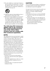
...the manufacturer's instructions. 8) Do not install near water. 6) Clean only with newspapers, tablecloths, curtains, etc. As an ENERGY STAR® partner, Sony Corporation has determined that produce heat. 9) Do not defeat the safety purpose of the polarized or grounding-type plug. Record these instructions. 3) Heed all...unit from being walked on the rear of electric shock to rain or moisture. If the provided plug does not fit into your Sony dealer regarding this product meets the ENERGY STAR® guidelines for your safety. ENERGY STAR® is intended to alert the ...
...the manufacturer's instructions. 8) Do not install near water. 6) Clean only with newspapers, tablecloths, curtains, etc. As an ENERGY STAR® partner, Sony Corporation has determined that produce heat. 9) Do not defeat the safety purpose of the polarized or grounding-type plug. Record these instructions. 3) Heed all...unit from being walked on the rear of electric shock to rain or moisture. If the provided plug does not fit into your Sony dealer regarding this product meets the ENERGY STAR® guidelines for your safety. ENERGY STAR® is intended to alert the ...
Operating Instructions
Page 3
...in this manual could void your authority to operate this equipment does cause harmful interference to radio or television reception, which the receiver is connected. - Other versions may cause harmful interference to avoid injury from the apparatus and the speakers. 3US If this ...core of time. 14) Refer all servicing to qualified service personnel. The following measures: - Increase the separation between the equipment and receiver. - Connect the equipment into the apparatus, the apparatus has been exposed to the version of the FCC Rules. Consult the dealer...
...in this manual could void your authority to operate this equipment does cause harmful interference to radio or television reception, which the receiver is connected. - Other versions may cause harmful interference to avoid injury from the apparatus and the speakers. 3US If this ...core of time. 14) Refer all servicing to qualified service personnel. The following measures: - Increase the separation between the equipment and receiver. - Connect the equipment into the apparatus, the apparatus has been exposed to the version of the FCC Rules. Consult the dealer...
Operating Instructions
Page 4
...the front panel. and worldwide patents issued & pending. In this manual describe the controls on the supplied remote. On Copyrights This receiver incorporates Dolby* Digital and Pro Logic Surround and the DTS** Digital Surround System. * Manufactured under U.S. DTS and DTS Digital Surround... 1996-2008 DTS, Inc. This receiver incorporates High-Definition Multimedia Interface (HDMITM) technology. Dolby, Pro Logic, and the double-D symbol are trademarks or registered trademarks of area code U only". • The instructions in the text, for model STR-DH500. HDMI, the HDMI logo and...
...the front panel. and worldwide patents issued & pending. In this manual describe the controls on the supplied remote. On Copyrights This receiver incorporates Dolby* Digital and Pro Logic Surround and the DTS** Digital Surround System. * Manufactured under U.S. DTS and DTS Digital Surround... 1996-2008 DTS, Inc. This receiver incorporates High-Definition Multimedia Interface (HDMITM) technology. Dolby, Pro Logic, and the double-D symbol are trademarks or registered trademarks of area code U only". • The instructions in the text, for model STR-DH500. HDMI, the HDMI logo and...
Operating Instructions
Page 5
...TV 15 4a: Connecting the audio components ........ 16 4b: Connecting the video components ........ 17 5: Connecting the antennas (aerials 22 6: Preparing the receiver and the remote..... 23 7: Adjusting the speaker levels and balance (TEST TONE 24 Playback Selecting a component 25 Listening/Watching a component 27 Amplifier... DIGITAL MEDIA PORT (DMPORT 49 Changing the display 52 Using the Sleep Timer 52 Recording using the receiver 53 Using the Remote Changing button assignments 53 Additional Information Glossary 54 Precautions 56 Troubleshooting 57 Specifications 61 Index 63 5US
...TV 15 4a: Connecting the audio components ........ 16 4b: Connecting the video components ........ 17 5: Connecting the antennas (aerials 22 6: Preparing the receiver and the remote..... 23 7: Adjusting the speaker levels and balance (TEST TONE 24 Playback Selecting a component 25 Listening/Watching a component 27 Amplifier... DIGITAL MEDIA PORT (DMPORT 49 Changing the display 52 Using the Sleep Timer 52 Recording using the receiver 53 Using the Remote Changing button assignments 53 Additional Information Glossary 54 Precautions 56 Troubleshooting 57 Specifications 61 Index 63 5US
Operating Instructions
Page 6
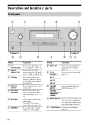
... E MASTER VOLUME F MUTING G DIMMER Function Press to adjust brightness of all speakers at the same time (page 25, 26, 27, 28). Receives signals from remote commander. Turn to turn the receiver on the display (page 52). L PHONES jack Connects to restore the sound (page 26). Turn to select the input source to...
... E MASTER VOLUME F MUTING G DIMMER Function Press to adjust brightness of all speakers at the same time (page 25, 26, 27, 28). Receives signals from remote commander. Turn to turn the receiver on the display (page 52). L PHONES jack Connects to restore the sound (page 26). Turn to select the input source to...

Operating Instructions
Page 7
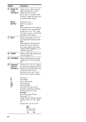
...HDMI DTS COAX 5 56 MEMORY PLI I D.RANGE MONO SLEEP ST D q; 9 8 7 Name A SW B LFE C Input indicators Function Lights up when the receiver is decoding DTS signals. However, "NO INPUT" appears on presetting radio stations, see page 47. A memory function, such as Preset Memory (page 47), etc., ...subwoofer selection is set to the preset station you have made digital connections and that INPUT MODE is selected. Lights up when the receiver recognizes a component connected via an HDMI IN jack (page 18). Monaural broadcast Stereo broadcast A preset station number appears when the ...
...HDMI DTS COAX 5 56 MEMORY PLI I D.RANGE MONO SLEEP ST D q; 9 8 7 Name A SW B LFE C Input indicators Function Lights up when the receiver is decoding DTS signals. However, "NO INPUT" appears on presetting radio stations, see page 47. A memory function, such as Preset Memory (page 47), etc., ...subwoofer selection is set to the preset station you have made digital connections and that INPUT MODE is selected. Lights up when the receiver recognizes a component connected via an HDMI IN jack (page 18). Monaural broadcast Stereo broadcast A preset station number appears when the ...
Operating Instructions
Page 8
Name Function F Dolby Pro Logic indicators Lights up one of the respective indicators when the receiver applies Dolby Pro Logic processing to 2 channel signals in order to show how the receiver downmixes the source sound (based on the speaker settings). L Front Left R Front Right C Center (monaural) SL ... R, etc.) indicate the channels being played back. PL Dolby Pro Logic PLII Dolby Pro Logic II Note These indicators do not light up when the receiver is set to "AUTO" (page 49). G D Lights up if both the center and surround speakers are set to "NO" (page 31) Sound...
Name Function F Dolby Pro Logic indicators Lights up one of the respective indicators when the receiver applies Dolby Pro Logic processing to 2 channel signals in order to show how the receiver downmixes the source sound (based on the speaker settings). L Front Left R Front Right C Center (monaural) SL ... R, etc.) indicate the channels being played back. PL Dolby Pro Logic PLII Dolby Pro Logic II Note These indicators do not light up when the receiver is set to "AUTO" (page 49). G D Lights up if both the center and surround speakers are set to "NO" (page 31) Sound...
Operating Instructions
Page 9
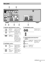
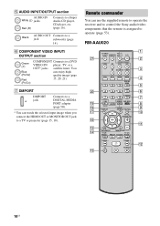
The image and the sound are output to the supplied FM wire antenna (aerial) (page 22). B ANTENNA section FM ANTENNA jack AM ANTENNA terminals Connects to a TV (page 18). The COAXIAL jack COAXIAL IN provides a better jack sound quality (page 18, 20, 21). D VIDEO/AUDIO INPUT/OUTPUT section AUDIO IN/ White (L) OUT jacks Red (R) Connects to a satellite tuner, DVD player or a Blu-ray disc player. VIDEO IN/ Yellow OUT* jacks continued 9US HDMI IN/ OUT* jacks Connects to a VCR, DVD player, etc. (page 15-22). Connects to the supplied AM loop antenna (aerial) (page 22). 3 C ...
The image and the sound are output to the supplied FM wire antenna (aerial) (page 22). B ANTENNA section FM ANTENNA jack AM ANTENNA terminals Connects to a TV (page 18). The COAXIAL jack COAXIAL IN provides a better jack sound quality (page 18, 20, 21). D VIDEO/AUDIO INPUT/OUTPUT section AUDIO IN/ White (L) OUT jacks Red (R) Connects to a satellite tuner, DVD player or a Blu-ray disc player. VIDEO IN/ Yellow OUT* jacks continued 9US HDMI IN/ OUT* jacks Connects to a VCR, DVD player, etc. (page 15-22). Connects to the supplied AM loop antenna (aerial) (page 22). 3 C ...
Operating Instructions
Page 10
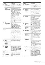
... SAT TV SA-CD/CD TUNER 2CH A.F.D. Black AUDIO OUT Connects to a jack subwoofer (page 14). You can use the supplied remote to operate the receiver and to control the Sony audio/video components that the remote is assigned to a TV or projector (page 15, 18).
... SAT TV SA-CD/CD TUNER 2CH A.F.D. Black AUDIO OUT Connects to a jack subwoofer (page 14). You can use the supplied remote to operate the receiver and to control the Sony audio/video components that the remote is assigned to a TV or projector (page 15, 18).
Operating Instructions
Page 11
... disc player. Press to replay the previous scene or fast forward the current scene of the receiver. Name Function A TV ?/1 Press TV ?/1 and TV (M) at (on/standby) the same time to turn off the receiver and other Sony components (SYSTEM STANDBY). If you press any of the VCR, CD player or Bluray disc...
... disc player. Press to replay the previous scene or fast forward the current scene of the receiver. Name Function A TV ?/1 Press TV ?/1 and TV (M) at (on/standby) the same time to turn off the receiver and other Sony components (SYSTEM STANDBY). If you press any of the VCR, CD player or Bluray disc...
Operating Instructions
Page 12
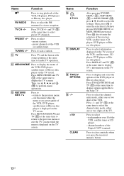
.... Press TOOLS/OPTIONS and TV (M) at the same time to enable TV operation. Press to select information displayed on the TV screen. Press to the Sony TV. and TV (M) at the same time to display options applicable to select - preset stations. - M TV Press TV and the button with orange printing... the menu while the menu or on the TV screen. Press also to select the channel entry mode, either one or two digits of the receiver, VCR, satellite tuner, CD player, DVD player or Bluray disc player. Press TV CH +/- PRESET +/- TUNING +/- and TV (M) at the same time to select - ...
.... Press TOOLS/OPTIONS and TV (M) at the same time to enable TV operation. Press to select information displayed on the TV screen. Press to the Sony TV. and TV (M) at the same time to display options applicable to select - preset stations. - M TV Press TV and the button with orange printing... the menu while the menu or on the TV screen. Press also to select the channel entry mode, either one or two digits of the receiver, VCR, satellite tuner, CD player, DVD player or Bluray disc player. Press TV CH +/- PRESET +/- TUNING +/- and TV (M) at the same time to select - ...
Operating Instructions
Page 13
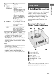
... +, TV VOL +, and H buttons have tactile dots. Use the tactile dots as an example only. Getting Started 1: Installing the speakers This receiver allows you want. 13US To fully enjoy theater-like multi channel surround sound requires five speakers (two front speakers, a center speaker, and two ...channels. Getting Started Name Function T Numeric buttons (number 5a)) U TV INPUT Press to activate the Sleep Timer function and the duration which the receiver turns off automatically. preset/tune to select track number 10. - Press the numeric buttons and TV (M) at the same time to use a...
... +, TV VOL +, and H buttons have tactile dots. Use the tactile dots as an example only. Getting Started 1: Installing the speakers This receiver allows you want. 13US To fully enjoy theater-like multi channel surround sound requires five speakers (two front speakers, a center speaker, and two ...channels. Getting Started Name Function T Numeric buttons (number 5a)) U TV INPUT Press to activate the Sleep Timer function and the duration which the receiver turns off automatically. preset/tune to select track number 10. - Press the numeric buttons and TV (M) at the same time to use a...
Operating Instructions
Page 14
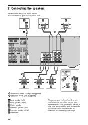
If the auto standby function is set to on, it turns to standby mode automatically based on the level of the input signal to disconnect the AC power cord (mains lead). F D A A I BD IN OUT ANTENNA AM VIDEO IN VIDEO IN VIDEO OUT VIDEO IN VIDEO OUT DVD IN MONITOR OUT NENT VIDEO IN IN AUDIO IN DVD AUDIO OUT MONITOR AUDIO IN AUDIO OUT SA-CD/CD TV SAT VIDEO SUBWOOFER B CENTER SURROUND R L FRONT L R SPEAKERS B 13/32 in. (10 mm) C E B A Monaural audio cord (not supplied) B Speaker cords (not supplied) AFront speaker (left) BFront speaker (right) CCenter speaker ...
If the auto standby function is set to on, it turns to standby mode automatically based on the level of the input signal to disconnect the AC power cord (mains lead). F D A A I BD IN OUT ANTENNA AM VIDEO IN VIDEO IN VIDEO OUT VIDEO IN VIDEO OUT DVD IN MONITOR OUT NENT VIDEO IN IN AUDIO IN DVD AUDIO OUT MONITOR AUDIO IN AUDIO OUT SA-CD/CD TV SAT VIDEO SUBWOOFER B CENTER SURROUND R L FRONT L R SPEAKERS B 13/32 in. (10 mm) C E B A Monaural audio cord (not supplied) B Speaker cords (not supplied) AFront speaker (left) BFront speaker (right) CCenter speaker ...
Operating Instructions
Page 15
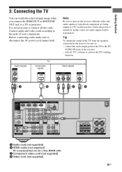
... OUT or MONITOR OUT jack to a TV or projector. Tip To output the sound of the receiver. - It is turned on the receiver when the video and audio signals of your components. connect the audio output jacks of the TV ... supplied) CENTER SURROUND R L FRONT L R SPEAKERS 15US turn on , neither video nor audio signals will be sure to the receiver, be transmitted. Audio signals TV Audio/video signals Note Be sure to connect all the cords. Unless the power is not necessary to...Getting Started 3: Connecting the TV You can watch the selected input image when you use a Sony HDMI cable.
... OUT or MONITOR OUT jack to a TV or projector. Tip To output the sound of the receiver. - It is turned on the receiver when the video and audio signals of your components. connect the audio output jacks of the TV ... supplied) CENTER SURROUND R L FRONT L R SPEAKERS 15US turn on , neither video nor audio signals will be sure to the receiver, be transmitted. Audio signals TV Audio/video signals Note Be sure to connect all the cords. Unless the power is not necessary to...Getting Started 3: Connecting the TV You can watch the selected input image when you use a Sony HDMI cable.
Operating Instructions
Page 16
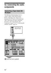
Super Audio CD player/CD player A HDMI CONNECT TO SAT IN DVD IN BD IN OUT DIGITAL INPUT FOR AUDIO ANTENNA AM BD IN SAT IN OPTICAL DVD IN COAXIAL DIGITAL DC5V 0.7A MAX DMPORT Y PB/CB VIDEO IN PR/CR SAT IN DVD IN MONITOR OUT COMPONENT VIDEO IN IN AUDIO IN L VIDEO IN VIDEO OUT DVD AUDIO OUT VIDEO IN VIDEO OUT MONITOR AUDIO IN AUDIO OUT R SA-CD/CD TV SAT VIDEO SUBWOOFER A Audio cord (not supplied) 16US Before connecting cords, make sure to "4b: Connecting the video components" (page 17) or "5: Connecting the antennas (aerials)" (page 22). After connecting ...
Super Audio CD player/CD player A HDMI CONNECT TO SAT IN DVD IN BD IN OUT DIGITAL INPUT FOR AUDIO ANTENNA AM BD IN SAT IN OPTICAL DVD IN COAXIAL DIGITAL DC5V 0.7A MAX DMPORT Y PB/CB VIDEO IN PR/CR SAT IN DVD IN MONITOR OUT COMPONENT VIDEO IN IN AUDIO IN L VIDEO IN VIDEO OUT DVD AUDIO OUT VIDEO IN VIDEO OUT MONITOR AUDIO IN AUDIO OUT R SA-CD/CD TV SAT VIDEO SUBWOOFER A Audio cord (not supplied) 16US Before connecting cords, make sure to "4b: Connecting the video components" (page 17) or "5: Connecting the antennas (aerials)" (page 22). After connecting ...
Operating Instructions
Page 17
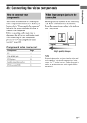
...be connected" below for the pages which describe how to disconnect the AC power cord (mains lead). Refer to this receiver. Unless the power is turned on the receiver when the video and audio signals of a playback component are being output to be connected Component Page TV 15 With HDMI... jack 18 DVD player 20 Satellite tuner/Set-top box 21 DVD recorder/VCR 22 Video input/output jacks to a TV via the receiver. Getting Started 4b: Connecting the video components How to connect your components This section describes how to connect your video components to the illustration...
...be connected" below for the pages which describe how to disconnect the AC power cord (mains lead). Refer to this receiver. Unless the power is turned on the receiver when the video and audio signals of a playback component are being output to be connected Component Page TV 15 With HDMI... jack 18 DVD player 20 Satellite tuner/Set-top box 21 DVD recorder/VCR 22 Video input/output jacks to a TV via the receiver. Getting Started 4b: Connecting the video components How to connect your components This section describes how to connect your video components to the illustration...
Operating Instructions
Page 18
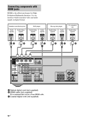
... AUDIO IN AUDIO OUT R SA-CD/CD TV SAT VIDEO SUBWOOFER A Optical digital cord (not supplied) B HDMI cable (not supplied) We recommend that you use a Sony HDMI cable. Satellite tuner/Set-top box Audio signals Audio/video signals DVD player Audio/video signals Audio signals Blu-ray disc player Audio/video...
... AUDIO IN AUDIO OUT R SA-CD/CD TV SAT VIDEO SUBWOOFER A Optical digital cord (not supplied) B HDMI cable (not supplied) We recommend that you use a Sony HDMI cable. Satellite tuner/Set-top box Audio signals Audio/video signals DVD player Audio/video signals Audio signals Blu-ray disc player Audio/video...
Operating Instructions
Page 19
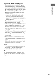
The input video signals cannot be output from the TV speaker only when a playback component and this receiver, as well as this receiver and the TV are connected via the HDMI cable. • This receiver may not be sure to - turn off TV's volume or activate the TV's muting function. • The multi/stereo... of a component connected via the HDMI jack. To output the sound from the HDMI OUT jack. Getting Started Notes on the playback component to the receiver. -
The input video signals cannot be output from the TV speaker only when a playback component and this receiver, as well as this receiver and the TV are connected via the HDMI cable. • This receiver may not be sure to - turn off TV's volume or activate the TV's muting function. • The multi/stereo... of a component connected via the HDMI jack. To output the sound from the HDMI OUT jack. Getting Started Notes on the playback component to the receiver. -
Operating Instructions
Page 20
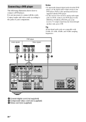
...Video cord (not supplied) CENTER SURROUND R L FRONT L R SPEAKERS 20US To output sound from the DVD player, set the digital audio output setting on the receiver. Refer to the DIGITAL COAXIAL DVD IN jack on the DVD player. Tip All the digital audio jacks are compatible with the DVD player. •...; As this receiver does not have analog audio input jacks for DVD, connect your components. It is not necessary to connect a DVD player. Connect audio and ...
...Video cord (not supplied) CENTER SURROUND R L FRONT L R SPEAKERS 20US To output sound from the DVD player, set the digital audio output setting on the receiver. Refer to the DIGITAL COAXIAL DVD IN jack on the DVD player. Tip All the digital audio jacks are compatible with the DVD player. •...; As this receiver does not have analog audio input jacks for DVD, connect your components. It is not necessary to connect a DVD player. Connect audio and ...
