
Operating Instructions
Page 2
... electric shock, do not cover the ventilation opening of the unit. As the main plug is used to disconnect the unit from the mains, connect the unit to excessive heat such as radiators, heat registers, stoves, or other . Excessive sound pressure from the AC outlet immediately. Record these...plug. To reduce the risk of fire, do not expose this apparatus near any ventilation openings. Serial No. Should you call upon your Sony dealer regarding this product meets the ENERGY STAR® guidelines for replacement of electric shock to constitute a risk of the obsolete outlet. ...
... electric shock, do not cover the ventilation opening of the unit. As the main plug is used to disconnect the unit from the mains, connect the unit to excessive heat such as radiators, heat registers, stoves, or other . Excessive sound pressure from the AC outlet immediately. Record these...plug. To reduce the risk of fire, do not expose this apparatus near any ventilation openings. Serial No. Should you call upon your Sony dealer regarding this product meets the ENERGY STAR® guidelines for replacement of electric shock to constitute a risk of the obsolete outlet. ...
Operating Instructions
Page 3
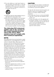
... that to touch the core of the speaker cord. 3) Connect the speaker cord to the apparatus and the speakers carefully so as not to which the receiver is used in the U.S.A. This equipment generates, uses and can be connected to the apparatus and the speakers in a particular installation.... When a cart is connected. - Consult the dealer or an experienced radio/TV technician for...
... that to touch the core of the speaker cord. 3) Connect the speaker cord to the apparatus and the speakers carefully so as not to which the receiver is used in the U.S.A. This equipment generates, uses and can be connected to the apparatus and the speakers in a particular installation.... When a cart is connected. - Consult the dealer or an experienced radio/TV technician for...
Operating Instructions
Page 5
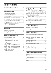
...location of parts 6 Getting Started 1: Installing the speakers 13 2: Connecting the speakers 14 3: Connecting the TV 15 4a: Connecting the audio components ........ 16 4b: Connecting the video components ........ 17 5: Connecting the antennas (aerials 22 6: Preparing the receiver and the remote..... 23 7: Adjusting the speaker levels and balance ...MEDIA PORT (DMPORT 49 Changing the display 52 Using the Sleep Timer 52 Recording using the receiver 53 Using the Remote Changing button assignments 53 Additional Information Glossary 54 Precautions 56 Troubleshooting 57 Specifications 61 Index 63 ...
...location of parts 6 Getting Started 1: Installing the speakers 13 2: Connecting the speakers 14 3: Connecting the TV 15 4a: Connecting the audio components ........ 16 4b: Connecting the video components ........ 17 5: Connecting the antennas (aerials 22 6: Preparing the receiver and the remote..... 23 7: Adjusting the speaker levels and balance ...MEDIA PORT (DMPORT 49 Changing the display 52 Using the Sleep Timer 52 Recording using the receiver 53 Using the Remote Changing button assignments 53 Additional Information Glossary 54 Precautions 56 Troubleshooting 57 Specifications 61 Index 63 ...
Operating Instructions
Page 6
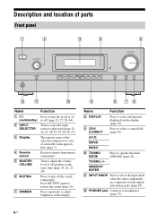
...MASTER VOLUME PHONES INPUT MODE TUNING MODE TUNING MEMORY/ 2CH/ ENTER A.DIRECT A.F.D. Name Function H DISPLAY Press to select a sound field (page 39). Receives signals from remote commander. I 2CH/ A.DIRECT Press to select information displayed on the display (page 52). MOVIE MUSIC DISPLAY DIMMER MUTING qs qa q;... (on or off the sound temporarily. MEMORY/ ENTER K INPUT MODE Press to select the input mode when the same components are connected to turn off (page 23, 27, 28, 44). The current status of the selected component or a list of all speakers at...
...MASTER VOLUME PHONES INPUT MODE TUNING MODE TUNING MEMORY/ 2CH/ ENTER A.DIRECT A.F.D. Name Function H DISPLAY Press to select a sound field (page 39). Receives signals from remote commander. I 2CH/ A.DIRECT Press to select information displayed on the display (page 52). MOVIE MUSIC DISPLAY DIMMER MUTING qs qa q;... (on or off the sound temporarily. MEMORY/ ENTER K INPUT MODE Press to select the input mode when the same components are connected to turn off (page 23, 27, 28, 44). The current status of the selected component or a list of all speakers at...

Operating Instructions
Page 7
... if INPUT MODE is set to "AUTO" (page 49). Note When playing a DTS format disc, be sure that you select. Lights up when the receiver recognizes a component connected via an HDMI IN jack (page 18). Name D DTS E Tuning indicators MEMORY MONO ST Function Lights up when BD input is selected. Monaural broadcast...
... if INPUT MODE is set to "AUTO" (page 49). Note When playing a DTS format disc, be sure that you select. Lights up when the receiver recognizes a component connected via an HDMI IN jack (page 18). Name D DTS E Tuning indicators MEMORY MONO ST Function Lights up when BD input is selected. Monaural broadcast...
Operating Instructions
Page 8
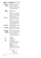
...) Example: Recording format (Front/ Surround): 3/2.1 Output channel: When surround speakers are set to "AUTO" (page 49). G D Lights up when the receiver is set to "NO" (page 31) Sound Field: A.F.D. Note When playing a Dolby Digital format disc, be sure that INPUT MODE is decoding Dolby ... speakers are set to "NO" (page 36) and you have made digital connections and that you select a sound field using the A.F.D. I D.RANGE Lights up one of the respective indicators when the receiver applies Dolby Pro Logic processing to 2 channel signals in order to show how ...
...) Example: Recording format (Front/ Surround): 3/2.1 Output channel: When surround speakers are set to "AUTO" (page 49). G D Lights up when the receiver is set to "NO" (page 31) Sound Field: A.F.D. Note When playing a Dolby Digital format disc, be sure that INPUT MODE is decoding Dolby ... speakers are set to "NO" (page 36) and you have made digital connections and that you select a sound field using the A.F.D. I D.RANGE Lights up one of the respective indicators when the receiver applies Dolby Pro Logic processing to 2 channel signals in order to show how ...
Operating Instructions
Page 9
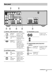
...VIDEO OUT MONITOR AUDIO IN AUDIO OUT R SA-CD/CD TV SAT VIDEO SUBWOOFER CENTER SURROUND R L FRONT L R SPEAKERS 76 5 4 A DIGITAL INPUT/OUTPUT section OPTICAL Connects to a satellite tuner, DVD player or a Blu-ray disc player. VIDEO IN/ Yellow OUT* jacks continued 9US HDMI IN/ OUT* jacks... Connects to a DVD IN jacks player, etc. The COAXIAL jack COAXIAL IN provides a better jack sound quality (page 18, 20, 21). D VIDEO/AUDIO INPUT/OUTPUT...
...VIDEO OUT MONITOR AUDIO IN AUDIO OUT R SA-CD/CD TV SAT VIDEO SUBWOOFER CENTER SURROUND R L FRONT L R SPEAKERS 76 5 4 A DIGITAL INPUT/OUTPUT section OPTICAL Connects to a satellite tuner, DVD player or a Blu-ray disc player. VIDEO IN/ Yellow OUT* jacks continued 9US HDMI IN/ OUT* jacks... Connects to a DVD IN jacks player, etc. The COAXIAL jack COAXIAL IN provides a better jack sound quality (page 18, 20, 21). D VIDEO/AUDIO INPUT/OUTPUT...
Operating Instructions
Page 10
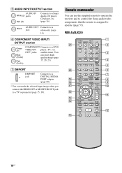
... AV ?/1 ?/1 SYSTEM STANDBY VIDEO BD DVD SAT TV SA-CD/CD TUNER 2CH A.F.D. E AUDIO INPUT/OUTPUT section AUDIO IN White (L) jacks Red (R) Connects to a DVD VIDEO IN/ player, TV, or a OUT* jacks satellite tuner. TV CH + PRESET - qa qs 10US Remote commander You can watch...page 15, 18). REPLAY ADVANCE PRESET + .< > < TUNING - G DMPORT DMPORT jack Connects to a DIGITAL MEDIA PORT adapter (page 50). * You can use the supplied remote to operate the receiver and to control the Sony audio/video components that the remote is assigned to a jack subwoofer (page 14). RM-AAU020...
... AV ?/1 ?/1 SYSTEM STANDBY VIDEO BD DVD SAT TV SA-CD/CD TUNER 2CH A.F.D. E AUDIO INPUT/OUTPUT section AUDIO IN White (L) jacks Red (R) Connects to a DVD VIDEO IN/ player, TV, or a OUT* jacks satellite tuner. TV CH + PRESET - qa qs 10US Remote commander You can watch...page 15, 18). REPLAY ADVANCE PRESET + .< > < TUNING - G DMPORT DMPORT jack Connects to a DIGITAL MEDIA PORT adapter (page 50). * You can use the supplied remote to operate the receiver and to control the Sony audio/video components that the remote is assigned to a jack subwoofer (page 14). RM-AAU020...
Operating Instructions
Page 14
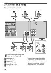
2: Connecting the speakers Before connecting cords, make sure to a subwoofer, then sound may not be output. 14US F D A A I BD IN OUT ANTENNA AM VIDEO IN VIDEO IN VIDEO OUT VIDEO IN ... audio cord (not supplied) B Speaker cords (not supplied) AFront speaker (left) BFront speaker (right) CCenter speaker DSurround speaker (left) ESurround speaker (right) FSubwoofer* * When you connect a subwoofer with an auto standby function, turn off the function when watching movies. If the auto standby function is set to on, it turns to...
2: Connecting the speakers Before connecting cords, make sure to a subwoofer, then sound may not be output. 14US F D A A I BD IN OUT ANTENNA AM VIDEO IN VIDEO IN VIDEO OUT VIDEO IN ... audio cord (not supplied) B Speaker cords (not supplied) AFront speaker (left) BFront speaker (right) CCenter speaker DSurround speaker (left) ESurround speaker (right) FSubwoofer* * When you connect a subwoofer with an auto standby function, turn off the function when watching movies. If the auto standby function is set to on, it turns to...
Operating Instructions
Page 15
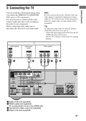
...supplied) We recommend that you connect the HDMI OUT or MONITOR ... TV via the receiver. connect the audio output jacks of the TV to the jacks of the receiver. - C Component... video cord (not supplied) D Video cord (not supplied) CENTER SURROUND R L FRONT L R SPEAKERS 15US Unless the power is not necessary to the receiver, be transmitted. Connect... audio and video cords according to the TV AUDIO IN jacks of your components. Before connecting cords, make sure to a TV or projector. Getting Started 3: Connecting...
...supplied) We recommend that you connect the HDMI OUT or MONITOR ... TV via the receiver. connect the audio output jacks of the TV to the jacks of the receiver. - C Component... video cord (not supplied) D Video cord (not supplied) CENTER SURROUND R L FRONT L R SPEAKERS 15US Unless the power is not necessary to the receiver, be transmitted. Connect... audio and video cords according to the TV AUDIO IN jacks of your components. Before connecting cords, make sure to a TV or projector. Getting Started 3: Connecting...
Operating Instructions
Page 16
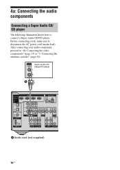
... Audio CD/ CD player The following illustration shows how to "4b: Connecting the video components" (page 17) or "5: Connecting the antennas (aerials)" (page 22). Super Audio CD player/CD player A HDMI CONNECT TO SAT IN DVD IN BD IN OUT DIGITAL INPUT FOR AUDIO ANTENNA AM BD IN SAT IN ... OUT VIDEO IN VIDEO OUT MONITOR AUDIO IN AUDIO OUT R SA-CD/CD TV SAT VIDEO SUBWOOFER A Audio cord (not supplied) 16US After connecting your audio component, proceed to connect a Super Audio CD/CD player. Before connecting cords, make sure to disconnect the AC power cord (mains lead).
... Audio CD/ CD player The following illustration shows how to "4b: Connecting the video components" (page 17) or "5: Connecting the antennas (aerials)" (page 22). Super Audio CD player/CD player A HDMI CONNECT TO SAT IN DVD IN BD IN OUT DIGITAL INPUT FOR AUDIO ANTENNA AM BD IN SAT IN ... OUT VIDEO IN VIDEO OUT MONITOR AUDIO IN AUDIO OUT R SA-CD/CD TV SAT VIDEO SUBWOOFER A Audio cord (not supplied) 16US After connecting your audio component, proceed to connect a Super Audio CD/CD player. Before connecting cords, make sure to disconnect the AC power cord (mains lead).
Operating Instructions
Page 17
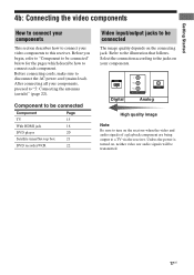
...signals of a playback component are being output to disconnect the AC power cord (mains lead). Before connecting cords, make sure to a TV via the receiver. Component to be connected Component Page TV 15 With HDMI jack 18 DVD player 20 Satellite tuner/Set-top box 21 DVD... recorder/VCR 22 Video input/output jacks to this receiver. Getting Started 4b: Connecting the video components How to connect your components This section describes how to connect your video components to be connected The image quality depends on the connecting jack. Unless the power is turned on, neither ...
...signals of a playback component are being output to disconnect the AC power cord (mains lead). Before connecting cords, make sure to a TV via the receiver. Component to be connected Component Page TV 15 With HDMI jack 18 DVD player 20 Satellite tuner/Set-top box 21 DVD... recorder/VCR 22 Video input/output jacks to this receiver. Getting Started 4b: Connecting the video components How to connect your components This section describes how to connect your video components to be connected The image quality depends on the connecting jack. Unless the power is turned on, neither ...
Operating Instructions
Page 18
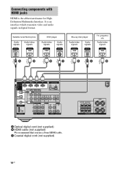
... Audio signals Blu-ray disc player Audio/video signals Audio signals TV, projector, etc. Audio/video signals A B B C B A B HDMI CONNECT TO SAT IN DVD IN BD IN OUT DIGITAL INPUT FOR AUDIO ANTENNA AM BD IN SAT IN OPTICAL DVD IN COAXIAL DIGITAL DC5V 0.7A...SUBWOOFER A Optical digital cord (not supplied) B HDMI cable (not supplied) We recommend that you use a Sony HDMI cable. It is the abbreviated name for HighDefinition Multimedia Interface. Connecting components with HDMI jacks HDMI is an interface which transmits video and audio signals in digital format. C Coaxial...
... Audio signals Blu-ray disc player Audio/video signals Audio signals TV, projector, etc. Audio/video signals A B B C B A B HDMI CONNECT TO SAT IN DVD IN BD IN OUT DIGITAL INPUT FOR AUDIO ANTENNA AM BD IN SAT IN OPTICAL DVD IN COAXIAL DIGITAL DC5V 0.7A...SUBWOOFER A Optical digital cord (not supplied) B HDMI cable (not supplied) We recommend that you use a Sony HDMI cable. It is the abbreviated name for HighDefinition Multimedia Interface. Connecting components with HDMI jacks HDMI is an interface which transmits video and audio signals in digital format. C Coaxial...
Operating Instructions
Page 19
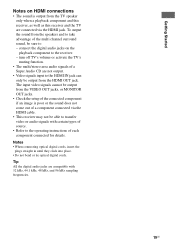
...19US Getting Started Notes on the playback component to the receiver. - To output the sound from the TV speaker only when a playback component and this receiver, as well as this receiver and the TV are connected via the HDMI cable. • This receiver may not be output from the VIDEO OUT jacks, ...or MONITOR OUT jacks. • Check the setup of the connected component if an image is output from ...
...19US Getting Started Notes on the playback component to the receiver. - To output the sound from the TV speaker only when a playback component and this receiver, as well as this receiver and the TV are connected via the HDMI cable. • This receiver may not be output from the VIDEO OUT jacks, ...or MONITOR OUT jacks. • Check the setup of the connected component if an image is output from ...
Operating Instructions
Page 20
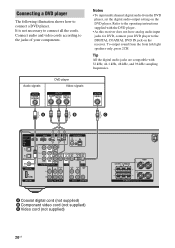
...and 96 kHz sampling frequencies. It is not necessary to connect a DVD player. Tip All the digital audio jacks are compatible with the DVD player. • As this receiver does not have analog audio input jacks for DVD, connect your DVD player to the jacks of your components. ...To output sound from the DVD player, set the digital audio output setting on the receiver. Connecting a DVD player The following illustration shows how to connect all the cords. Connect audio and video cords according to the DIGITAL COAXIAL DVD IN jack on the DVD player. Audio...
...and 96 kHz sampling frequencies. It is not necessary to connect a DVD player. Tip All the digital audio jacks are compatible with the DVD player. • As this receiver does not have analog audio input jacks for DVD, connect your DVD player to the jacks of your components. ...To output sound from the DVD player, set the digital audio output setting on the receiver. Connecting a DVD player The following illustration shows how to connect all the cords. Connect audio and video cords according to the DIGITAL COAXIAL DVD IN jack on the DVD player. Audio...
Operating Instructions
Page 21
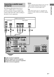
...All the digital audio jacks are compatible with 32 kHz, 44.1 kHz, 48 kHz, and 96 kHz sampling frequencies. Notes • When connecting optical digital cords, insert the plugs straight in until they click into place. • Do not bend or tie optical digital cords. Audio ...signals Satellite tuner/set -top box. Getting Started Connecting a satellite tuner/ set-top box The following illustration shows how to connect a satellite tuner or a set -top box Video signals A B C D HDMI CONNECT TO SAT IN DVD IN BD IN OUT DIGITAL INPUT FOR AUDIO ANTENNA...
...All the digital audio jacks are compatible with 32 kHz, 44.1 kHz, 48 kHz, and 96 kHz sampling frequencies. Notes • When connecting optical digital cords, insert the plugs straight in until they click into place. • Do not bend or tie optical digital cords. Audio ...signals Satellite tuner/set -top box. Getting Started Connecting a satellite tuner/ set-top box The following illustration shows how to connect a satellite tuner or a set -top box Video signals A B C D HDMI CONNECT TO SAT IN DVD IN BD IN OUT DIGITAL INPUT FOR AUDIO ANTENNA...
Operating Instructions
Page 22
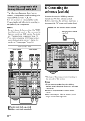
...how to fully extend the FM wire antenna (aerial). • After connecting the FM wire antenna (aerial), keep the AM loop antenna (aerial) away from the receiver and other components. • Be sure to connect a component which has analog jacks such as possible. It is not ...B Video cord (not supplied) 22US For details, see "Changing button assignments" (page 53). • You can use the button to connect all the cords. Before connecting the antennas, make sure to the jacks of this receiver. Connect audio and video cords according to disconnect the AC power cord (mains lead).
...how to fully extend the FM wire antenna (aerial). • After connecting the FM wire antenna (aerial), keep the AM loop antenna (aerial) away from the receiver and other components. • Be sure to connect a component which has analog jacks such as possible. It is not ...B Video cord (not supplied) 22US For details, see "Changing button assignments" (page 53). • You can use the button to connect all the cords. Before connecting the antennas, make sure to the jacks of this receiver. Connect audio and video cords according to disconnect the AC power cord (mains lead).
Operating Instructions
Page 23
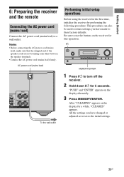
Getting Started 6: Preparing the receiver and the remote Connecting the AC power cord (mains lead) Connect the AC power cord (mains lead) to their factory defaults. This procedure can also be used to return settings you have made to a wall outlet...2CH/ ENTER A.DIRECT A.F.D. "PUSH" and "ENTER" appears on the display for the first time, initialize the receiver by performing the following procedure. After "CLEARING" appears on the display alternately. 3 Press MEMORY/ENTER. Notes • Before connecting the AC power cord (mains lead), make sure that the stripped end of the speaker cords...
Getting Started 6: Preparing the receiver and the remote Connecting the AC power cord (mains lead) Connect the AC power cord (mains lead) to their factory defaults. This procedure can also be used to return settings you have made to a wall outlet...2CH/ ENTER A.DIRECT A.F.D. "PUSH" and "ENTER" appears on the display for the first time, initialize the receiver by performing the following procedure. After "CLEARING" appears on the display alternately. 3 Press MEMORY/ENTER. Notes • Before connecting the AC power cord (mains lead), make sure that the stripped end of the speaker cords...
Operating Instructions
Page 25
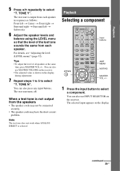
...the display. Tips • To adjust the level of the test tone sounds the same from the speakers • The speaker cords may not be connected securely. • The speaker cords may have the short-circuit problem. For details, see "Adjusting the level (LEVEL menu)" (page 32). You... can also use MASTER VOLUME on the receiver. Playback 5 Press V/v repeatedly to select a component. Note The test tone does not work when ANALOG DIRECT is not output from each speaker. When...
...the display. Tips • To adjust the level of the test tone sounds the same from the speakers • The speaker cords may not be connected securely. • The speaker cords may have the short-circuit problem. For details, see "Adjusting the level (LEVEL menu)" (page 32). You... can also use MASTER VOLUME on the receiver. Playback 5 Press V/v repeatedly to select a component. Note The test tone does not work when ANALOG DIRECT is not output from each speaker. When...
Operating Instructions
Page 26
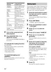
...character. 7 Press V/v to select a character, then press B/b to move the cursor to turn off the receiver. Selected input Components that can [Display] be played back DMPORT [DMPORT] DIGITAL MEDIA PORT adapter connected to the DMPORT jack VIDEO [VIDEO] VCR, etc., connected to the VIDEO jack BD [BD] Blu-ray disc player, etc... SA-CD/CD [SA-CD/CD] Super Audio CD/CD player, etc., connected to adjust the volume. to the SA-CD/CD jack TUNER Built-in radio tuner [FM or AM band] 2 Turn on the receiver. To avoid damaging your speakers Before you turn down the volume level. The ...
...character. 7 Press V/v to select a character, then press B/b to move the cursor to turn off the receiver. Selected input Components that can [Display] be played back DMPORT [DMPORT] DIGITAL MEDIA PORT adapter connected to the DMPORT jack VIDEO [VIDEO] VCR, etc., connected to the VIDEO jack BD [BD] Blu-ray disc player, etc... SA-CD/CD [SA-CD/CD] Super Audio CD/CD player, etc., connected to adjust the volume. to the SA-CD/CD jack TUNER Built-in radio tuner [FM or AM band] 2 Turn on the receiver. To avoid damaging your speakers Before you turn down the volume level. The ...


