
Operating Instructions
Page 1
3-854-213-14 (1) Remote Control Unit Operating Instructions GB Mode d'emploi FR Manual de instrucciones ES Gebrauchsanweisung DE RM-BR300 © 2004 Sony Corporation 3854213140
3-854-213-14 (1) Remote Control Unit Operating Instructions GB Mode d'emploi FR Manual de instrucciones ES Gebrauchsanweisung DE RM-BR300 © 2004 Sony Corporation 3854213140
Operating Instructions
Page 2
... for EMC and product safety is Sony Corporation, 1-7-1 Konan, Minato-ku, Tokyo, Japan. In the event of Conformity Trade Name: SONY Model: RM-BR300 Responsible party: Sony Electronics Inc. Increase the separation between...RM-BR300 Serial No. Please ensure that the socket outlet is subject to provide reasonable protection against harmful interference in a particular installation. These limits are designed to the following measures: - For the customers in accordance with the instructions, may result in this manual could void your Sony dealer regarding this unit...
... for EMC and product safety is Sony Corporation, 1-7-1 Konan, Minato-ku, Tokyo, Japan. In the event of Conformity Trade Name: SONY Model: RM-BR300 Responsible party: Sony Electronics Inc. Increase the separation between...RM-BR300 Serial No. Please ensure that the socket outlet is subject to provide reasonable protection against harmful interference in a particular installation. These limits are designed to the following measures: - For the customers in accordance with the instructions, may result in this manual could void your Sony dealer regarding this unit...
Operating Instructions
Page 3
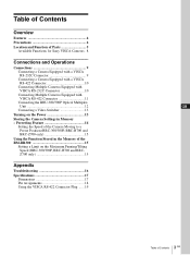
Table of Contents Overview Features 4 Precautions 4 Location and Function of Parts 5 Available Functions for Sony VISCA Cameras . 8 Connections and Operations Connections 9 Connecting a Camera Equipped with a VISCA RS-232C Connector 9 Connecting a Camera Equipped with a VISCA RS-422 Connector ... Cameras Equipped with VISCA RS-422 Connector 11 Connecting the BRU-300/300P Optical Multiplex Unit 12 Connecting a Video Switcher 13 Turning on the Power 13 Storing the Camera Settings in the Memory of the RM-BR300 15 Setting a Limit on the Maximum Panning/Tilting Speed (BRC-300/300P, BRC-...
Table of Contents Overview Features 4 Precautions 4 Location and Function of Parts 5 Available Functions for Sony VISCA Cameras . 8 Connections and Operations Connections 9 Connecting a Camera Equipped with a VISCA RS-232C Connector 9 Connecting a Camera Equipped with a VISCA RS-422 Connector ... Cameras Equipped with VISCA RS-422 Connector 11 Connecting the BRU-300/300P Optical Multiplex Unit 12 Connecting a Video Switcher 13 Turning on the Power 13 Storing the Camera Settings in the Memory of the RM-BR300 15 Setting a Limit on the Maximum Panning/Tilting Speed (BRC-300/300P, BRC-...
Operating Instructions
Page 4
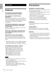
...factory or in materials equal in the memory of the camera. * The number of positions to be saved differs depending on the unit, you can control the following locations may damage the surface finishes. 4 GB Features / Precautions A tally lamp input/contact output terminal (9pin connector...focus adjustment, AE adjustment, one-push auto white balance adjustment and backlight compensation. Stubborn stains can be saved.) Controllable Sony VISCA cameras The unit can easily perform various camera adjustments such as pan/tilt/zoom positions and other camera adjustment values in quality. The...
...factory or in materials equal in the memory of the camera. * The number of positions to be saved differs depending on the unit, you can control the following locations may damage the surface finishes. 4 GB Features / Precautions A tally lamp input/contact output terminal (9pin connector...focus adjustment, AE adjustment, one-push auto white balance adjustment and backlight compensation. Stubborn stains can be saved.) Controllable Sony VISCA cameras The unit can easily perform various camera adjustments such as pan/tilt/zoom positions and other camera adjustment values in quality. The...
Operating Instructions
Page 5
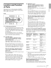
... item (SHUTTER or IRIS) selected on the camera. When the BRC-H700 or BRC-Z700 camera is connected, the function of the control with the MODE button of this unit, the functions of the 5 Location and Function of Parts GB The AUTO/MANUAL button is selected with the MODE button (with the... BRC-300/300P, BRCH700 or BRC-Z700 camera. For details, see "Functions of the R and B controls for the BRCH700 and BRC-Z700 cameras" on...
... item (SHUTTER or IRIS) selected on the camera. When the BRC-H700 or BRC-Z700 camera is connected, the function of the control with the MODE button of this unit, the functions of the 5 Location and Function of Parts GB The AUTO/MANUAL button is selected with the MODE button (with the... BRC-300/300P, BRCH700 or BRC-Z700 camera. For details, see "Functions of the R and B controls for the BRCH700 and BRC-Z700 cameras" on...
Operating Instructions
Page 6
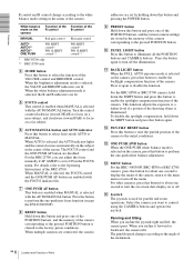
... to enable the backlight compensation function of the camera. When you can adjust the focus manually if AF ASSIST is illuminated. E FOCUS control This control is enabled when MANUAL is used for about one second to turn off the menu. O Joystick The joystick is selected with the AUTO... main menu or turn off the illumination. When multiple cameras are connected, the camera addresses are stored in the center of the VALUE/R control and BRIGHT/B control. N MENU button For the BRC-300/300P, BRC-H700 or BRC-Z700 camera, press this button to select the function of the ...
... to enable the backlight compensation function of the camera. When you can adjust the focus manually if AF ASSIST is illuminated. E FOCUS control This control is enabled when MANUAL is used for about one second to turn off the menu. O Joystick The joystick is selected with the AUTO... main menu or turn off the illumination. When multiple cameras are connected, the camera addresses are stored in the center of the VALUE/R control and BRIGHT/B control. N MENU button For the BRC-300/300P, BRC-H700 or BRC-Z700 camera, press this button to select the function of the ...
Operating Instructions
Page 7
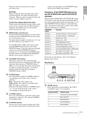
...right. Yellow green: The camera is connected. Full Auto mode Position 8 Automatic Exposure - OFF For details on . Overview When you the direct control of the camera without the menu displayed, the pan/tilt/zoom are reset and the camera returns to the front. P SHIFT button and indicators ...Press this button and press POSITION button 1 (STD). To reset the direction, hold down this unit, the unit automatically detects the camera model and the functions of positions 7 to 16 of the POSITION buttons change as the pan, tilt and zoom ...
...right. Yellow green: The camera is connected. Full Auto mode Position 8 Automatic Exposure - OFF For details on . Overview When you the direct control of the camera without the menu displayed, the pan/tilt/zoom are reset and the camera returns to the front. P SHIFT button and indicators ...Press this button and press POSITION button 1 (STD). To reset the direction, hold down this unit, the unit automatically detects the camera model and the functions of positions 7 to 16 of the POSITION buttons change as the pan, tilt and zoom ...
Operating Instructions
Page 8
... connector Connect to the VISCA RS-232C IN connector of Parts CONTACT (TALLY): The contact output corresponding to the camera address selected with this unit is used for the SNC-RZ30N/ RZ30P. Switch 2 (Communication baud rate selector) Set to ON for RS-422, or OFF for RS...Be sure to ON for IRIS and GAIN adjustments, or OFF for Sony VISCA Cameras The functions of the controls, buttons and connectors in blue and the tally lamp of the connector using the TALLY/CONTACT selector. Parts B VALUE/R control C BRIGHT/B control G ONE PUSH AF button L PAN-TILT RESET button N MENU button...
... connector Connect to the VISCA RS-232C IN connector of Parts CONTACT (TALLY): The contact output corresponding to the camera address selected with this unit is used for the SNC-RZ30N/ RZ30P. Switch 2 (Communication baud rate selector) Set to ON for RS-422, or OFF for RS...Be sure to ON for IRIS and GAIN adjustments, or OFF for Sony VISCA Cameras The functions of the controls, buttons and connectors in blue and the tally lamp of the connector using the TALLY/CONTACT selector. Parts B VALUE/R control C BRIGHT/B control G ONE PUSH AF button L PAN-TILT RESET button N MENU button...

Operating Instructions
Page 9
...DC IN 12V to AC outlet VISCA RS-232C IN RS-232C cable (supplied) (SONY: 1-590-879-3X) VISCA RS-232C DC IN 12V AC power cord (supplied) to the Operating Instructions supplied with this unit. 2 Connect this unit to RS-232C. For connections with a VISCA RS-232C Connector 1 Connect this... unit to the camera using the VISCA RS-232C connectors, check that the DIP switch on the connection ...
...DC IN 12V to AC outlet VISCA RS-232C IN RS-232C cable (supplied) (SONY: 1-590-879-3X) VISCA RS-232C DC IN 12V AC power cord (supplied) to the Operating Instructions supplied with this unit. 2 Connect this unit to RS-232C. For connections with a VISCA RS-232C Connector 1 Connect this... unit to the camera using the VISCA RS-232C connectors, check that the DIP switch on the connection ...
Operating Instructions
Page 10
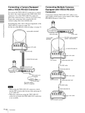
... RS-232C Camera BRC300/300P to AC outlet RS-232C cable (supplied) (SONY: 1-590-879-3X) to AC outlet VISCA RS-422 VISCA RS-422 ... power adaptor MPA-AC1 (supplied) Notes • When using the VISCA RS-422 connectors, check that come with this unit. For making the cable, refer to AC outlet Second camera VISCA RS-232C OUT RS-232C cable VISCA RS-232C IN...VIDEO IN VISCA RS-232C OUT DC IN 12V to VISCA RS-232C IN to seven cameras with a single RM-BR300 Remote Control Unit. Use of up to Seventh camera 10 GB Connections EXT SYNC IN VIDEO S VIDEO IN VISCA RS-232C OUT...
... RS-232C Camera BRC300/300P to AC outlet RS-232C cable (supplied) (SONY: 1-590-879-3X) to AC outlet VISCA RS-422 VISCA RS-422 ... power adaptor MPA-AC1 (supplied) Notes • When using the VISCA RS-422 connectors, check that come with this unit. For making the cable, refer to AC outlet Second camera VISCA RS-232C OUT RS-232C cable VISCA RS-232C IN...VIDEO IN VISCA RS-232C OUT DC IN 12V to VISCA RS-232C IN to seven cameras with a single RM-BR300 Remote Control Unit. Use of up to Seventh camera 10 GB Connections EXT SYNC IN VIDEO S VIDEO IN VISCA RS-232C OUT...
Operating Instructions
Page 11
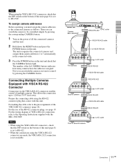
Now you can switch the camera to be controlled simply by pressing the CAMERA button. Notes • When using the VISCA RS-422 connectors, check that the DIP switch on the bottom of this unit and check that the CAMERA buttons light. EXT SYNC IN VIDEO S VIDEO IN VISCA RS-...VISCA RS-232C connection is set to 7 automatically in the connected order. 3 Press the POWER button on this unit (page 8) is not available. To assign camera addresses Before operating, you want to control by pressing the corresponding CAMERA button. 1 Turn on the power of the VISCA RS-422 connector (page 18...
Now you can switch the camera to be controlled simply by pressing the CAMERA button. Notes • When using the VISCA RS-422 connectors, check that the DIP switch on the bottom of this unit and check that the CAMERA buttons light. EXT SYNC IN VIDEO S VIDEO IN VISCA RS-...VISCA RS-232C connection is set to 7 automatically in the connected order. 3 Press the POWER button on this unit (page 8) is not available. To assign camera addresses Before operating, you want to control by pressing the corresponding CAMERA button. 1 Turn on the power of the VISCA RS-422 connector (page 18...
Operating Instructions
Page 12
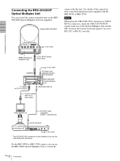
...) Video monitor, etc. For details of this unit. R 1 2 3 OFF ON 75 IR SELECT 1 2 3 4 5 6 7 8 9 VISCA RS-422 ! RS-232C cable (supplied)* (SONY: 1-590-879-3X) VISCA RS-232C to AC outlet * The VISCA RS-422 connection is also available if you can control the camera using the VISCA RS-232C connectors or... VISCA RS-422 connectors, check the VISCA FUNCTION switch on the rear of the Optical Multiplex Unit and the ...
...) Video monitor, etc. For details of this unit. R 1 2 3 OFF ON 75 IR SELECT 1 2 3 4 5 6 7 8 9 VISCA RS-422 ! RS-232C cable (supplied)* (SONY: 1-590-879-3X) VISCA RS-232C to AC outlet * The VISCA RS-422 connection is also available if you can control the camera using the VISCA RS-232C connectors or... VISCA RS-422 connectors, check the VISCA FUNCTION switch on the rear of the Optical Multiplex Unit and the ...
Operating Instructions
Page 13
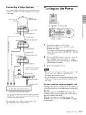
... 7 8 9 VISCA RS-422 ! CONTACT(TALLY) TALLY 1 9 1 9 CONTACT DC IN 12V ON/OFF TALLY/CONTACT to contact control terminal to composite video input 75-ohm coaxial cable* Video switcher (commercially available) * You can turn the camera on or off and the... STANDBY lamp lights on the camera. 13 Turning on the power of the unit. Turning on the Power 1 2 RESET PANEL LIGHT VALUE LOCK - + R BRIGHT MODE - + B FOCUS... OUT DC IN 12V VISCA RS-232C IN RS-232C cable (supplied) (SONY: 1-590-879-3X) VISCA RS-232C MODE RS-232C VISCA RS-422 TALLY/CONTACT ! ...
... 7 8 9 VISCA RS-422 ! CONTACT(TALLY) TALLY 1 9 1 9 CONTACT DC IN 12V ON/OFF TALLY/CONTACT to contact control terminal to composite video input 75-ohm coaxial cable* Video switcher (commercially available) * You can turn the camera on or off and the... STANDBY lamp lights on the camera. 13 Turning on the power of the unit. Turning on the Power 1 2 RESET PANEL LIGHT VALUE LOCK - + R BRIGHT MODE - + B FOCUS... OUT DC IN 12V VISCA RS-232C IN RS-232C cable (supplied) (SONY: 1-590-879-3X) VISCA RS-232C MODE RS-232C VISCA RS-422 TALLY/CONTACT ! ...

Operating Instructions
Page 14
... can be used for more than one second, if necessary. To recall the stored settings Select the function of the POSITION 1 to 8 buttons using this unit. To cancel the preset memory Select the function of the POSITION 1 to 8 buttons by pressing the SHIFT button for positions 1 to 8. The lower indicator will...
... can be used for more than one second, if necessary. To recall the stored settings Select the function of the POSITION 1 to 8 buttons using this unit. To cancel the preset memory Select the function of the POSITION 1 to 8 buttons by pressing the SHIFT button for positions 1 to 8. The lower indicator will...
Operating Instructions
Page 15
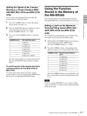
... 7 flash. 2 Press the CAMERA button corresponding to the speed you connect another camera to the pressed POSITION button with the RM-BR300 is set , as shown in the memory of this unit, set the speed of the camera moving to a preset position between 9 and 16, hold down the SHIFT button and press.../sec. 23.3 degrees/sec. 43 degrees/sec. 60 degrees/sec. (default) Now the camera will move to the position preset to this unit. Note If you use another RM-BR300 or you want to set the speed for more than a second while pressing the SHIFT button. All the CAMERA buttons, 1 to set ...
... 7 flash. 2 Press the CAMERA button corresponding to the speed you connect another camera to the pressed POSITION button with the RM-BR300 is set , as shown in the memory of this unit, set the speed of the camera moving to a preset position between 9 and 16, hold down the SHIFT button and press.../sec. 23.3 degrees/sec. 43 degrees/sec. 60 degrees/sec. (default) Now the camera will move to the position preset to this unit. Note If you use another RM-BR300 or you want to set the speed for more than a second while pressing the SHIFT button. All the CAMERA buttons, 1 to set ...
Operating Instructions
Page 16
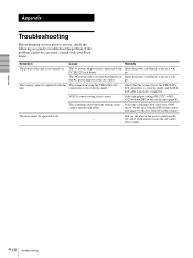
... baud rate, 9,600 bps or 38,400 bps, with the The connection using the VISCA RS-422 unit. Appendix Troubleshooting Before bringing in your Sony dealer. The AC power cord is selected on the unit (page 8) which is not inserted firmly into the AC outlet after a while. The camera cannot be... service, check the following as it will DC IN 12V jack firmly. The unit cannot be operated with the DIP switch on the camera. connectors is not correct. VISCA control setting is not correctly made , and the RS422 cable is not connected to the Insert the power cord firmly as...
... baud rate, 9,600 bps or 38,400 bps, with the The connection using the VISCA RS-422 unit. Appendix Troubleshooting Before bringing in your Sony dealer. The AC power cord is selected on the unit (page 8) which is not inserted firmly into the AC outlet after a while. The camera cannot be... service, check the following as it will DC IN 12V jack firmly. The unit cannot be operated with the DIP switch on the camera. connectors is not correct. VISCA control setting is not correctly made , and the RS422 cable is not connected to the Insert the power cord firmly as...
Operating Instructions
Page 17
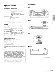
...CAMERA 1234567 391.3 (15 1/2) Front 45.9 (1 13/16) Side 30 30 185 (7 3/8) Bottom Unit: mm (inches) 17 Specifications GB Appendix Specifications Input/output connectors Control input/output VISCA RS-232C OUT: Mini DIN 8pin type VISCA RS-422: 9-pin type TALLY IN....9 mm (w/h/d) (15 1/2 × 7 3/8 × 5 3/4 inches) Approx. 950 g (2 lb 15 oz) Supplied accessories MPA-AC1 AC power adaptor (Sony) (1) AC power cord (1) RS-232C connecting cable (1) RS-422 connector plug (2) Operating Instructions (1) Design and specifications are subject to change without notice. Note Always ...
...CAMERA 1234567 391.3 (15 1/2) Front 45.9 (1 13/16) Side 30 30 185 (7 3/8) Bottom Unit: mm (inches) 17 Specifications GB Appendix Specifications Input/output connectors Control input/output VISCA RS-232C OUT: Mini DIN 8pin type VISCA RS-422: 9-pin type TALLY IN....9 mm (w/h/d) (15 1/2 × 7 3/8 × 5 3/4 inches) Approx. 950 g (2 lb 15 oz) Supplied accessories MPA-AC1 AC power adaptor (Sony) (1) AC power cord (1) RS-232C connecting cable (1) RS-422 connector plug (2) Operating Instructions (1) Design and specifications are subject to change without notice. Note Always ...

Operating Instructions
Page 18
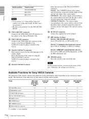
Appendix Pin Assignments VISCA RS-232C output connector (mini DIN 8pin, female) RS-232C Pin No. 1 2 3 4 5 6 7 8 Function No Connection No Connection TXD IN GND RXD IN GND No Connection No Connection VISCA RS-422 connector (connector plug, 9-pin) VISCA RS-422 Pin No. 1 2 3 4 5 6 7 8 9 1 9 Function No Connection No Connection No Connection No Connection GND RXD INRXD IN+ TXD INTXD IN+ TALLY/CONTACT connector (connector plug, 9-pin) TALLY/CONTACT Pin No. 1 2 3 4 5 6 7 8 9 1 9 Function CAMERA1 CAMERA2 CAMERA3 CAMERA4 CAMERA5 CAMERA6 CAMERA7 GND GND 18 GB Specifications
Appendix Pin Assignments VISCA RS-232C output connector (mini DIN 8pin, female) RS-232C Pin No. 1 2 3 4 5 6 7 8 Function No Connection No Connection TXD IN GND RXD IN GND No Connection No Connection VISCA RS-422 connector (connector plug, 9-pin) VISCA RS-422 Pin No. 1 2 3 4 5 6 7 8 9 1 9 Function No Connection No Connection No Connection No Connection GND RXD INRXD IN+ TXD INTXD IN+ TALLY/CONTACT connector (connector plug, 9-pin) TALLY/CONTACT Pin No. 1 2 3 4 5 6 7 8 9 1 9 Function CAMERA1 CAMERA2 CAMERA3 CAMERA4 CAMERA5 CAMERA6 CAMERA7 GND GND 18 GB Specifications
Operating Instructions
Page 19
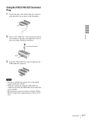
Flat-head screwdriver Wire 3 Insert the VISCA RS-422 connector plug into the desired wire opening on the plug, and tighten the screw for that wire using the VISCA RS-422 connectors are made, the VISCA RS-232C connection is not available. • The maximum connection distance with the VISCA RS-422 connection is approximately 1,200 m (3,937 feet). 19 Specifications GB Appendix Using the VISCA RS-422 Connector Plug 1 Grasp both ends of the VISCA RS-422 connector plug and pull it out as shown in the illustration. 1 9 2 Insert a wire (AWG Nos. 28 to 18) into the VISCA RS-422 connector. 1 9 ...
Flat-head screwdriver Wire 3 Insert the VISCA RS-422 connector plug into the desired wire opening on the plug, and tighten the screw for that wire using the VISCA RS-422 connectors are made, the VISCA RS-232C connection is not available. • The maximum connection distance with the VISCA RS-422 connection is approximately 1,200 m (3,937 feet). 19 Specifications GB Appendix Using the VISCA RS-422 Connector Plug 1 Grasp both ends of the VISCA RS-422 connector plug and pull it out as shown in the illustration. 1 9 2 Insert a wire (AWG Nos. 28 to 18) into the VISCA RS-422 connector. 1 9 ...

Operating Instructions
Page 80
Sony Corporation Printed in Japan Printed on recycled paper using VOC (Volatile Organic Compound)-free vegetable oil based ink.
Sony Corporation Printed in Japan Printed on recycled paper using VOC (Volatile Organic Compound)-free vegetable oil based ink.