
Operating Instructions
Page 1
3-854-213-14 (1) Remote Control Unit Operating Instructions GB Mode d'emploi FR Manual de instrucciones ES Gebrauchsanweisung DE RM-BR300 © 2004 Sony Corporation 3854213140
3-854-213-14 (1) Remote Control Unit Operating Instructions GB Mode d'emploi FR Manual de instrucciones ES Gebrauchsanweisung DE RM-BR300 © 2004 Sony Corporation 3854213140
Operating Instructions
Page 2
...operations, disconnect the mains plug. All interface cables used to disconnect mains power. The Authorized Representative for a Class B digital device, pursuant to Part 15 of FCC Rules. Refer servicing to radio communications. Please ensure that any questions about this product, you call ; In the event of Conformity Trade Name: SONY Model: RM-BR300...this equipment is located on this unit. ATTENTION The electromagnetic fields at the specific frequencies may result in accordance with the instructions, may cause undesired operation. Increase the separation between the ...
...operations, disconnect the mains plug. All interface cables used to disconnect mains power. The Authorized Representative for a Class B digital device, pursuant to Part 15 of FCC Rules. Refer servicing to radio communications. Please ensure that any questions about this product, you call ; In the event of Conformity Trade Name: SONY Model: RM-BR300...this equipment is located on this unit. ATTENTION The electromagnetic fields at the specific frequencies may result in accordance with the instructions, may cause undesired operation. Increase the separation between the ...
Operating Instructions
Page 3
... Setting the Speed of Contents GB Table of Contents Overview Features 4 Precautions 4 Location and Function of Parts 5 Available Functions for Sony VISCA Cameras . 8 Connections and Operations Connections 9 Connecting a Camera Equipped with a VISCA RS-232C Connector 9 Connecting a Camera Equipped with a VISCA RS-422 Connector ... VISCA RS-422 Connector 11 Connecting the BRU-300/300P Optical Multiplex Unit 12 Connecting a Video Switcher 13 Turning on the Power 13 Storing the Camera Settings in the Memory of the RM-BR300 15 Setting a Limit on the Maximum Panning/Tilting Speed (BRC-300...
... Setting the Speed of Contents GB Table of Contents Overview Features 4 Precautions 4 Location and Function of Parts 5 Available Functions for Sony VISCA Cameras . 8 Connections and Operations Connections 9 Connecting a Camera Equipped with a VISCA RS-232C Connector 9 Connecting a Camera Equipped with a VISCA RS-422 Connector ... VISCA RS-422 Connector 11 Connecting the BRU-300/300P Optical Multiplex Unit 12 Connecting a Video Switcher 13 Turning on the Power 13 Storing the Camera Settings in the Memory of the RM-BR300 15 Setting a Limit on the Maximum Panning/Tilting Speed (BRC-300...
Operating Instructions
Page 4
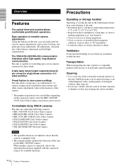
..., AE adjustment, one-push auto white balance adjustment and backlight compensation. Easy operation of positions to be saved differs depending on the unit, you can be saved.) Controllable Sony VISCA cameras The unit can control the following locations may damage the surface finishes. 4 GB Features / Precautions ... the BRC-300/300P camera. The unit is capable of controlling up to 16 combinations* of camera settings such as radios or TV transmitters • Locations subject to those that the camera is connected, refer to the Operating Instructions supplied with a small quantity of...
..., AE adjustment, one-push auto white balance adjustment and backlight compensation. Easy operation of positions to be saved differs depending on the unit, you can be saved.) Controllable Sony VISCA cameras The unit can control the following locations may damage the surface finishes. 4 GB Features / Precautions ... the BRC-300/300P camera. The unit is capable of controlling up to 16 combinations* of camera settings such as radios or TV transmitters • Locations subject to those that the camera is connected, refer to the Operating Instructions supplied with a small quantity of...
Operating Instructions
Page 5
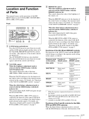
...to the white balance mode selected on the camera. When the BRIGHT indicator is selected with the MODE button of this unit, the functions of the 5 Location and Function of Parts GB The AUTO/MANUAL button is selected with the MODE button ...When the white balance adjustment mode is used Brightness level control MANUAL GAIN Pri*** Shutter speed control Gain control*** Iris control** Exposure compensation level control* * When the exposure compensation function is activated on the camera. ** Iris and gain controls are operable for the BRCH700 and BRC-Z700 cameras" on page 5....
...to the white balance mode selected on the camera. When the BRIGHT indicator is selected with the MODE button of this unit, the functions of the 5 Location and Function of Parts GB The AUTO/MANUAL button is selected with the MODE button ...When the white balance adjustment mode is used Brightness level control MANUAL GAIN Pri*** Shutter speed control Gain control*** Iris control** Exposure compensation level control* * When the exposure compensation function is activated on the camera. ** Iris and gain controls are operable for the BRCH700 and BRC-Z700 cameras" on page 5....
Operating Instructions
Page 6
... if a portion of the camera. When you want to control using the CAMERA buttons and operate the joystick. Overview R control and B control change according to the white balance mode setting in the menu of the VALUE/R control and BRIGHT/B control. White balance mode on the camera, press this button for... pan/tilt and zoom operations. When MANUAL is illuminated. H RESET button Hold down the SHIFT button and press this...
... if a portion of the camera. When you want to control using the CAMERA buttons and operate the joystick. Overview R control and B control change according to the white balance mode setting in the menu of the VALUE/R control and BRIGHT/B control. White balance mode on the camera, press this button for... pan/tilt and zoom operations. When MANUAL is illuminated. H RESET button Hold down the SHIFT button and press this...

Operating Instructions
Page 9
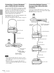
...1 2 3 OFF ON 75 IR SELECT 1 2 3 4 5 6 7 8 9 VISCA RS-422 ! For connections with other cameras, refer to the Operating Instructions supplied with this unit. 2 Connect this unit to RS-232C. Note When using the RS-232C connecting cable supplied with the camera you will connect. Connecting cables Use the...9 Connections GB Connections and Operations Connections and Operations Connections This section focuses on the bottom of this system. EXT SYNC IN VIDEO S VIDEO IN VISCA RS-232C OUT DC IN 12V to AC outlet VISCA RS-232C IN RS-232C cable (supplied) (SONY: 1-590-879-3X) ...
...1 2 3 OFF ON 75 IR SELECT 1 2 3 4 5 6 7 8 9 VISCA RS-422 ! For connections with other cameras, refer to the Operating Instructions supplied with this unit. 2 Connect this unit to RS-232C. Note When using the RS-232C connecting cable supplied with the camera you will connect. Connecting cables Use the...9 Connections GB Connections and Operations Connections and Operations Connections This section focuses on the bottom of this system. EXT SYNC IN VIDEO S VIDEO IN VISCA RS-232C OUT DC IN 12V to AC outlet VISCA RS-232C IN RS-232C cable (supplied) (SONY: 1-590-879-3X) ...
Operating Instructions
Page 10
Connections and Operations Connecting a Camera Equipped with a VISCA RS-422 Connector You can use of up... 18). Camera BRC-300/300P Connecting Multiple Cameras Equipped with VISCA RS-232C Connector Connections with the VISCA RS-232C cables (cross type) enable control of the RS-422 connector plugs, see page 19. R 1 2 3 OFF ON 75 IR SELECT 1 2 3 4 5 6 7... using the VISCA RS-422 connectors, check that come with a single RM-BR300 Remote Control Unit. VISCA RS-232C Camera BRC300/300P to AC outlet RS-232C cable (supplied) (SONY: 1-590-879-3X) to AC outlet VISCA RS-422 VISCA RS-...
Connections and Operations Connecting a Camera Equipped with a VISCA RS-422 Connector You can use of up... 18). Camera BRC-300/300P Connecting Multiple Cameras Equipped with VISCA RS-232C Connector Connections with the VISCA RS-232C cables (cross type) enable control of the RS-422 connector plugs, see page 19. R 1 2 3 OFF ON 75 IR SELECT 1 2 3 4 5 6 7... using the VISCA RS-422 connectors, check that come with a single RM-BR300 Remote Control Unit. VISCA RS-232C Camera BRC300/300P to AC outlet RS-232C cable (supplied) (SONY: 1-590-879-3X) to AC outlet VISCA RS-422 VISCA RS-...
Operating Instructions
Page 11
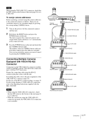
... cable using the RS-422 connector plug that comes with VISCA RS-422 Connector Connection via the VISCA RS-422 connectors enables control of the lit CAMERA buttons indicates how many cameras have the addresses assigned. Notes • When using the VISCA RS-422... RS-422 R 1 2 3 OFF ON 75 IR SELECT 1 2 3 4 5 6 7 8 9 VISCA RS-422 ! To assign camera addresses Before operating, you can switch the camera to the connected cameras as follows. The unit recognizes the connected cameras and assigns them camera addresses 1 to VISCA RS-422 R 1 2 3 OFF ON 75 IR SELECT 1 2 3 4 5 6 ...
... cable using the RS-422 connector plug that comes with VISCA RS-422 Connector Connection via the VISCA RS-422 connectors enables control of the lit CAMERA buttons indicates how many cameras have the addresses assigned. Notes • When using the VISCA RS-422... RS-422 R 1 2 3 OFF ON 75 IR SELECT 1 2 3 4 5 6 7 8 9 VISCA RS-422 ! To assign camera addresses Before operating, you can switch the camera to the connected cameras as follows. The unit recognizes the connected cameras and assigns them camera addresses 1 to VISCA RS-422 R 1 2 3 OFF ON 75 IR SELECT 1 2 3 4 5 6 ...
Operating Instructions
Page 12
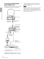
...BRC-Z700 camera, you use the BRU-H700 Optical Multiplex Unit to control the 12 GB Connections Camera BRC-300/300P camera with this unit (page 8) are set to the Operating Instructions supplied with the BRU-300/300P) BRU-300/300P Optical Multiplex Unit VISCA RS-232C IN 75-ohm coaxial cable (or ... to RS-232C or RS-422 correctly. RS-232C cable (supplied)* (SONY: 1-590-879-3X) VISCA RS-232C to AC outlet AC power cord (supplied with the BRC-H700 or BRC-Z700. Connections and Operations Connecting the BRU-300/300P Optical Multiplex Unit You can use the VISCA RS-422 connectors.
...BRC-Z700 camera, you use the BRU-H700 Optical Multiplex Unit to control the 12 GB Connections Camera BRC-300/300P camera with this unit (page 8) are set to the Operating Instructions supplied with the BRU-300/300P) BRU-300/300P Optical Multiplex Unit VISCA RS-232C IN 75-ohm coaxial cable (or ... to RS-232C or RS-422 correctly. RS-232C cable (supplied)* (SONY: 1-590-879-3X) VISCA RS-232C to AC outlet AC power cord (supplied with the BRC-H700 or BRC-Z700. Connections and Operations Connecting the BRU-300/300P Optical Multiplex Unit You can use the VISCA RS-422 connectors.
Operating Instructions
Page 13
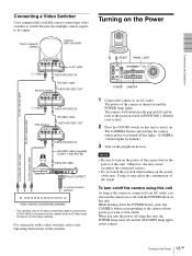
... camera using this unit. EXT SYNC IN VIDEO S VIDEO IN VISCA RS-232C OUT DC IN 12V VISCA RS-232C IN RS-232C cable (supplied) (SONY: 1-590-879-3X) VISCA RS-232C MODE RS-232C VISCA RS-422 TALLY/CONTACT ! Connections and Operations Connecting a Video Switcher Use a commercially available contact-control type video switcher...
... camera using this unit. EXT SYNC IN VIDEO S VIDEO IN VISCA RS-232C OUT DC IN 12V VISCA RS-232C IN RS-232C cable (supplied) (SONY: 1-590-879-3X) VISCA RS-232C MODE RS-232C VISCA RS-422 TALLY/CONTACT ! Connections and Operations Connecting a Video Switcher Use a commercially available contact-control type video switcher...

Operating Instructions
Page 14
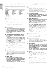
Connections and Operations Storing the Camera Settings in the memory of the camera using the SHIFT button, if necessary. The POSITION 1 to 8 buttons can be used for positions 1 ..., zooming, focusing, and backlighting, can be stored in which you release the SHIFT button, the upper indicator lights and the POSITION 1 to 8 buttons using this unit. To store in positions 9 to 8, press the SHIFT button so that the lower indicator lights. To store in positions 1 to 16, press the SHIFT button...
Connections and Operations Storing the Camera Settings in the memory of the camera using the SHIFT button, if necessary. The POSITION 1 to 8 buttons can be used for positions 1 ..., zooming, focusing, and backlighting, can be stored in which you release the SHIFT button, the upper indicator lights and the POSITION 1 to 8 buttons using this unit. To store in positions 9 to 8, press the SHIFT button so that the lower indicator lights. To store in positions 1 to 16, press the SHIFT button...
Operating Instructions
Page 15
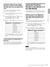
... stored in the table below. Using the Function Stored in the Memory of the RM-BR300 The following function for panning/tilting operations with the selected speed. Note If you use another RM-BR300 or you connect another camera to this unit. CAMERA button Maximum panning/tilting speed 1 3.5 degrees/sec. 2 6.4 degrees/sec. 3 11 degrees/sec. 4 18...
... stored in the table below. Using the Function Stored in the Memory of the RM-BR300 The following function for panning/tilting operations with the selected speed. Note If you use another RM-BR300 or you connect another camera to this unit. CAMERA button Maximum panning/tilting speed 1 3.5 degrees/sec. 2 6.4 degrees/sec. 3 11 degrees/sec. 4 18...
Operating Instructions
Page 16
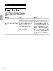
...switch on the unit (page 8) which...unit for service, check the following as a guide to troubleshoot the problem. Appendix 16 GB Troubleshooting The camera cannot be operated...unit. The AC power adaptor is selected on . The AC power cord is properly connected. connectors is not correct. VISCA control... setting is not correctly made , and the RS422 cable is not inserted firmly into the AC outlet after a while. Check that the connection to the Insert the power cord firmly as far as it will the AC power adaptor or the AC outlet. The unit cannot be operated...
...switch on the unit (page 8) which...unit for service, check the following as a guide to troubleshoot the problem. Appendix 16 GB Troubleshooting The camera cannot be operated...unit. The AC power adaptor is selected on . The AC power cord is properly connected. connectors is not correct. VISCA control... setting is not correctly made , and the RS422 cable is not inserted firmly into the AC outlet after a while. Check that the connection to the Insert the power cord firmly as far as it will the AC power adaptor or the AC outlet. The unit cannot be operated...
Operating Instructions
Page 17
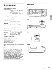
...CAMERA 1234567 391.3 (15 1/2) Front 45.9 (1 13/16) Side 30 30 185 (7 3/8) Bottom Unit: mm (inches) 17 Specifications GB Appendix Specifications Input/output connectors Control input/output VISCA RS-232C OUT: Mini DIN 8pin type VISCA RS-422: 9-pin type TALLY IN...(w/h/d) (15 1/2 × 7 3/8 × 5 3/4 inches) Approx. 950 g (2 lb 15 oz) Supplied accessories MPA-AC1 AC power adaptor (Sony) (1) AC power cord (1) RS-232C connecting cable (1) RS-422 connector plug (2) Operating Instructions (1) Design and specifications are subject to change without notice. Note Always verify that the...
...CAMERA 1234567 391.3 (15 1/2) Front 45.9 (1 13/16) Side 30 30 185 (7 3/8) Bottom Unit: mm (inches) 17 Specifications GB Appendix Specifications Input/output connectors Control input/output VISCA RS-232C OUT: Mini DIN 8pin type VISCA RS-422: 9-pin type TALLY IN...(w/h/d) (15 1/2 × 7 3/8 × 5 3/4 inches) Approx. 950 g (2 lb 15 oz) Supplied accessories MPA-AC1 AC power adaptor (Sony) (1) AC power cord (1) RS-232C connecting cable (1) RS-422 connector plug (2) Operating Instructions (1) Design and specifications are subject to change without notice. Note Always verify that the...


