
Operating Instructions
Page 3
...Parts 5 Available Functions for Sony VISCA Cameras . 8 Connections and Operations Connections 9 Connecting a Camera Equipped with a VISCA RS-232C Connector 9 Connecting a Camera Equipped with a VISCA RS-422 Connector 10 Connecting Multiple Cameras Equipped with VISCA RS-232C Connector 10 Connecting Multiple Cameras Equipped with VISCA RS-422... Connector 11 Connecting the BRU-300/300P Optical Multiplex Unit 12 Connecting a Video Switcher 13 Turning on the Power 13 Storing the Camera Settings in the Memory of the RM-BR300 15 Setting a Limit on the Maximum Panning/Tilting Speed (...
...Parts 5 Available Functions for Sony VISCA Cameras . 8 Connections and Operations Connections 9 Connecting a Camera Equipped with a VISCA RS-232C Connector 9 Connecting a Camera Equipped with a VISCA RS-422 Connector 10 Connecting Multiple Cameras Equipped with VISCA RS-232C Connector 10 Connecting Multiple Cameras Equipped with VISCA RS-422... Connector 11 Connecting the BRU-300/300P Optical Multiplex Unit 12 Connecting a Video Switcher 13 Turning on the Power 13 Storing the Camera Settings in the Memory of the RM-BR300 15 Setting a Limit on the Maximum Panning/Tilting Speed (...
Operating Instructions
Page 4
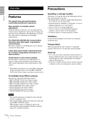
... sources of powerful electromagnetic radiation, such as pan/tilt/zoom positions and other camera adjustment values in the memory of the camera. * The number of positions to be saved differs depending on the unit, you can be saved.) Controllable Sony VISCA cameras The unit can control the following locations may damage the surface finishes. 4 GB Features / Precautions Easy...
... sources of powerful electromagnetic radiation, such as pan/tilt/zoom positions and other camera adjustment values in the memory of the camera. * The number of positions to be saved differs depending on the unit, you can be saved.) Controllable Sony VISCA cameras The unit can control the following locations may damage the surface finishes. 4 GB Features / Precautions Easy...
Operating Instructions
Page 5
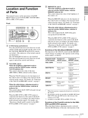
... the R. When the BRIGHT indicator is lit, the function of the control varies according to the exposure mode selected on the camera. The AUTO/MANUAL button is selected with the MODE button (with the MODE button of this unit, the functions of the 5 Location and Function of Parts GB When the white balance...
... the R. When the BRIGHT indicator is lit, the function of the control varies according to the exposure mode selected on the camera. The AUTO/MANUAL button is selected with the MODE button (with the MODE button of this unit, the functions of the 5 Location and Function of Parts GB When the white balance...
Operating Instructions
Page 6
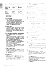
...shooting object is selected on the camera Function of the R control MANUAL Red gain control AUTO* AUTO1** AUTO2** ONE PUSH WB SHIFT control* WB R.SHIFT control** * BRC-H700 only ** BRC-Z700 only Function of the B control Blue gain control WB SHIFT control* WB B.SHIFT control** D MODE button Press this ...tilt speed changes according to the angle of the inclination. 6 GB Location and Function of the camera. Panning and tilting When you want to control using the CAMERA buttons and operate the joystick. H RESET button Hold down the SHIFT button and press this button...
...shooting object is selected on the camera Function of the R control MANUAL Red gain control AUTO* AUTO1** AUTO2** ONE PUSH WB SHIFT control* WB R.SHIFT control** * BRC-H700 only ** BRC-Z700 only Function of the B control Blue gain control WB SHIFT control* WB B.SHIFT control** D MODE button Press this ...tilt speed changes according to the angle of the inclination. 6 GB Location and Function of the camera. Panning and tilting When you want to control using the CAMERA buttons and operate the joystick. H RESET button Hold down the SHIFT button and press this button...
Operating Instructions
Page 7
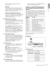
...wg wh wj wk U MODE selector Select the position corresponding to the VISCAcontrollable camera to the status of the connected camera(s). P SHIFT button and indicators Press this unit, the unit automatically detects the camera model and the functions of positions 7 to 16 of the POSITION buttons change... and EVI-D70/D70P cameras When the EVI-D100/D100P or EVI-D70/D70P camera is on. When you the direct control of the camera without the menu displayed, the pan/tilt/zoom are reset and the camera returns to 8. Switch position 0 1 2 3 4 Camera mode Automatically selected (default...
...wg wh wj wk U MODE selector Select the position corresponding to the VISCAcontrollable camera to the status of the connected camera(s). P SHIFT button and indicators Press this unit, the unit automatically detects the camera model and the functions of positions 7 to 16 of the POSITION buttons change... and EVI-D70/D70P cameras When the EVI-D100/D100P or EVI-D70/D70P camera is on. When you the direct control of the camera without the menu displayed, the pan/tilt/zoom are reset and the camera returns to 8. Switch position 0 1 2 3 4 Camera mode Automatically selected (default...
Operating Instructions
Page 8
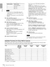
...BRC-H700 BRC-Z700 Notes • Use position 1 to the VISCA RS-422 connector of the camera or the Optical Multiplex Unit. An RS-422 connector plug is used for all the connected cameras are the same for the tally lamp input or the contact output. Select the function of Parts... Set to ON for 38,400bps, or OFF for IRIS adjustment only. Available Functions for Sony VISCA Cameras The functions of the controls, buttons and connectors in blue and the tally lamp of the selected camera lights. An RS-422 connector plug is shortcircuited against the connected switcher and the tally lamp...
...BRC-H700 BRC-Z700 Notes • Use position 1 to the VISCA RS-422 connector of the camera or the Optical Multiplex Unit. An RS-422 connector plug is used for all the connected cameras are the same for the tally lamp input or the contact output. Select the function of Parts... Set to ON for 38,400bps, or OFF for IRIS adjustment only. Available Functions for Sony VISCA Cameras The functions of the controls, buttons and connectors in blue and the tally lamp of the selected camera lights. An RS-422 connector plug is shortcircuited against the connected switcher and the tally lamp...

Operating Instructions
Page 9
... a VISCA RS-232C Connector 1 Connect this unit to the camera using the RS-232C connecting cable supplied with the camera you will connect. EXT SYNC IN VIDEO S VIDEO IN VISCA RS-232C OUT DC IN 12V to AC outlet VISCA RS-232C IN RS-232C cable (supplied) (SONY: 1-590-879-3X) VISCA RS-232C... DC IN 12V AC power cord (supplied) to the Operating Instructions supplied with this unit. 2 Connect...
... a VISCA RS-232C Connector 1 Connect this unit to the camera using the RS-232C connecting cable supplied with the camera you will connect. EXT SYNC IN VIDEO S VIDEO IN VISCA RS-232C OUT DC IN 12V to AC outlet VISCA RS-232C IN RS-232C cable (supplied) (SONY: 1-590-879-3X) VISCA RS-232C... DC IN 12V AC power cord (supplied) to the Operating Instructions supplied with this unit. 2 Connect...
Operating Instructions
Page 10
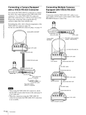
...422 connector (page 18). For the use the VISCA RS-422 connectors to connect this unit to seven cameras with a single RM-BR300 Remote Control Unit. VISCA RS-232C Camera BRC300/300P to AC outlet RS-232C cable (supplied) (SONY: 1-590-879-3X) to AC outlet VISCA RS-422 VISCA RS-422 cable VISCA RS...200 m (3,937 feet) away. Camera BRC-300/300P Connecting Multiple Cameras Equipped with VISCA RS-232C Connector Connections with the VISCA RS-232C cables (cross type) enable control of up to the pin assignments of this unit (page 8) is set to AC outlet First camera VISCA RS-232C OUT RS-232C ...
...422 connector (page 18). For the use the VISCA RS-422 connectors to connect this unit to seven cameras with a single RM-BR300 Remote Control Unit. VISCA RS-232C Camera BRC300/300P to AC outlet RS-232C cable (supplied) (SONY: 1-590-879-3X) to AC outlet VISCA RS-422 VISCA RS-422 cable VISCA RS...200 m (3,937 feet) away. Camera BRC-300/300P Connecting Multiple Cameras Equipped with VISCA RS-232C Connector Connections with the VISCA RS-232C cables (cross type) enable control of up to the pin assignments of this unit (page 8) is set to AC outlet First camera VISCA RS-232C OUT RS-232C ...
Operating Instructions
Page 11
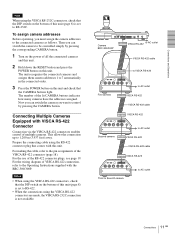
... to 1,200 m (3,937 feet) away. For making the cable, refer to Seventh camera 11 Connections GB To assign camera addresses Before operating, you want to control by pressing the corresponding CAMERA button. 1 Turn on the power of all the connetcted cameras and this unit. 2 Hold down the RESET button and press the POWER button on this...
... to 1,200 m (3,937 feet) away. For making the cable, refer to Seventh camera 11 Connections GB To assign camera addresses Before operating, you want to control by pressing the corresponding CAMERA button. 1 Turn on the power of all the connetcted cameras and this unit. 2 Hold down the RESET button and press the POWER button on this...
Operating Instructions
Page 12
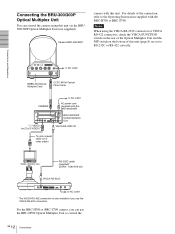
... or BRC-Z700 camera, you use the BRU-H700 Optical Multiplex Unit to RS-232C or RS-422 correctly. R 1 2 3 OFF ON 75 IR SELECT 1 2 3 4 5 6 7 8 9 VISCA RS-422 ! For details of this unit (page 8) are set to control the 12 GB Connections RS-232C cable (supplied)* (SONY: 1-590-879-3X...) VISCA RS-232C to AC outlet * The VISCA RS-422 connection is also available if you can control the camera using the VISCA RS-232C connectors or VISCA RS...
... or BRC-Z700 camera, you use the BRU-H700 Optical Multiplex Unit to RS-232C or RS-422 correctly. R 1 2 3 OFF ON 75 IR SELECT 1 2 3 4 5 6 7 8 9 VISCA RS-422 ! For details of this unit (page 8) are set to control the 12 GB Connections RS-232C cable (supplied)* (SONY: 1-590-879-3X...) VISCA RS-232C to AC outlet * The VISCA RS-422 connection is also available if you can control the camera using the VISCA RS-232C connectors or VISCA RS...
Operating Instructions
Page 13
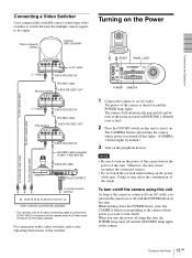
... RS-232C IN RS-232C cable (supplied) (SONY: 1-590-879-3X) VISCA RS-232C MODE RS-232C VISCA RS-422 TALLY/CONTACT ! The CAMERA button representing the camera whose power you turn on this unit to an AC outlet. The camera will automatically pan and tilt and be output. Otherwise... TALLY/CONTACT to contact control terminal to composite video input 75-ohm coaxial cable* Video switcher (commercially available) * You can turn on/off the camera using this unit As long as the camera is turned on the power of the camera before the power of the camera is connected to AC ...
... RS-232C IN RS-232C cable (supplied) (SONY: 1-590-879-3X) VISCA RS-232C MODE RS-232C VISCA RS-422 TALLY/CONTACT ! The CAMERA button representing the camera whose power you turn on this unit to an AC outlet. The camera will automatically pan and tilt and be output. Otherwise... TALLY/CONTACT to contact control terminal to composite video input 75-ohm coaxial cable* Video switcher (commercially available) * You can turn on/off the camera using this unit As long as the camera is turned on the power of the camera before the power of the camera is connected to AC ...

Operating Instructions
Page 14
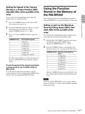
...AWB MENU POSITION 12345678 9 10 11 12 13 14 15 16 STD REV CAMERA 1234567 4 2 1 Press the PAN-TILT RESET button to reset the pan/ tilt position. 2 Press the CAMERA button to 8 buttons using this unit. The pressed button flashes during canceling of the POSITION 1 to select the... camera whose settings you cannot call up, store or cancel the settings in positions 9 to 16. ...
...AWB MENU POSITION 12345678 9 10 11 12 13 14 15 16 STD REV CAMERA 1234567 4 2 1 Press the PAN-TILT RESET button to reset the pan/ tilt position. 2 Press the CAMERA button to 8 buttons using this unit. The pressed button flashes during canceling of the POSITION 1 to select the... camera whose settings you cannot call up, store or cancel the settings in positions 9 to 16. ...
Operating Instructions
Page 15
... in the memory of this unit, set . Only the CAMERA button you pressed flashes, and the corresponding maximum panning/tilting speed is stored in the Memory of the RM-BR300 GB Note If you use another RM-BR300 or you connect another camera to this unit. Connections and Operations Setting the... Speed of the Camera Moving to a Preset Position (BRC300/300P, BRC-H700 and BRC-Z700 ...
... in the memory of this unit, set . Only the CAMERA button you pressed flashes, and the corresponding maximum panning/tilting speed is stored in the Memory of the RM-BR300 GB Note If you use another RM-BR300 or you connect another camera to this unit. Connections and Operations Setting the... Speed of the Camera Moving to a Preset Position (BRC300/300P, BRC-H700 and BRC-Z700 ...
Operating Instructions
Page 16
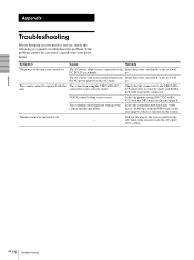
...cannot be corrected, consult with the DIP switch on the unit (page 8). go . Appendix Troubleshooting Before bringing in your Sony dealer. Pull out the plug of the camera and the unit differ. go . VISCA control setting is properly connected. The AC power adaptor is ...selected on . The camera cannot be operated at all. Select the proper...
...cannot be corrected, consult with the DIP switch on the unit (page 8). go . Appendix Troubleshooting Before bringing in your Sony dealer. Pull out the plug of the camera and the unit differ. go . VISCA control setting is properly connected. The AC power adaptor is ...selected on . The camera cannot be operated at all. Select the proper...
Operating Instructions
Page 17
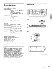
...Mini DIN 8pin type VISCA RS-422: 9-pin type TALLY IN/CONTACT OUT: 9-pin type Control signal format 9,600 bps/38,400 bps Data: 8 bit Stop bit: 1 Power connector...× 5 3/4 inches) Approx. 950 g (2 lb 15 oz) Supplied accessories MPA-AC1 AC power adaptor (Sony) (1) AC power cord (1) RS-232C connecting cable (1) RS-422 connector plug (2) Operating Instructions (1) Design and specifications are subject to change without...12 13 14 15 16 STD REV CAMERA 1234567 391.3 (15 1/2) Front 45.9 (1 13/16) Side 30 30 185 (7 3/8) Bottom Unit: mm (inches) 17 Specifications GB Note Always verify that...
...Mini DIN 8pin type VISCA RS-422: 9-pin type TALLY IN/CONTACT OUT: 9-pin type Control signal format 9,600 bps/38,400 bps Data: 8 bit Stop bit: 1 Power connector...× 5 3/4 inches) Approx. 950 g (2 lb 15 oz) Supplied accessories MPA-AC1 AC power adaptor (Sony) (1) AC power cord (1) RS-232C connecting cable (1) RS-422 connector plug (2) Operating Instructions (1) Design and specifications are subject to change without...12 13 14 15 16 STD REV CAMERA 1234567 391.3 (15 1/2) Front 45.9 (1 13/16) Side 30 30 185 (7 3/8) Bottom Unit: mm (inches) 17 Specifications GB Note Always verify that...
