
Child Safety: It Makes A Difference Where Your TV Stands
Page 1
The home theater entertainment experience is a growing trend, and larger televisions are popular purchases and are not always supported on this hidden hazard of the home with furniture and television sets. 5 Avoid placing any items on top of TVs such as VCRs and remotes that may pique the children's curiosity. 6 Remember that children can become excited while watching a program and can potentially push or pull a TV over and may fall over . 7 Share our safety message on the proper TV stands. The industry is committed to advocate children's safety and educate customers and their families ...
The home theater entertainment experience is a growing trend, and larger televisions are popular purchases and are not always supported on this hidden hazard of the home with furniture and television sets. 5 Avoid placing any items on top of TVs such as VCRs and remotes that may pique the children's curiosity. 6 Remember that children can become excited while watching a program and can potentially push or pull a TV over and may fall over . 7 Share our safety message on the proper TV stands. The industry is committed to advocate children's safety and educate customers and their families ...

Limited Warranty (U.S. Only)
Page 1
... This warranty does not cover Products sold AS IS or WITH ALL FAULTS, or consumables (such as follows: 1. PARTS: In addition, Sony will repair or replace the Product, at its original packaging or packaging affording an equal degree of the Product, including the antenna. This warranty...or modification of a service problem, or for all labor charges. 2. This warranty gives you specific legal rights, and you must be defective, Sony will supply, at no charge, new or rebuilt replacements in exchange for defective parts for one (1) year. This warranty is determined to be ...
... This warranty does not cover Products sold AS IS or WITH ALL FAULTS, or consumables (such as follows: 1. PARTS: In addition, Sony will repair or replace the Product, at its original packaging or packaging affording an equal degree of the Product, including the antenna. This warranty...or modification of a service problem, or for all labor charges. 2. This warranty gives you specific legal rights, and you must be defective, Sony will supply, at no charge, new or rebuilt replacements in exchange for defective parts for one (1) year. This warranty is determined to be ...

Operating Instructions
Page 1
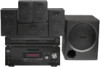
3-097-354-11(1) Home Theatre System Operating Instructions Owner's Record The model and serial numbers are located on the rear of the unit. Serial No. HT-DDW995 ©2007 Sony Corporation Model No. Refer to them whenever you call upon your Sony dealer regarding this product. Record the serial number in the space provided below.
3-097-354-11(1) Home Theatre System Operating Instructions Owner's Record The model and serial numbers are located on the rear of the unit. Serial No. HT-DDW995 ©2007 Sony Corporation Model No. Refer to them whenever you call upon your Sony dealer regarding this product. Record the serial number in the space provided below.

Operating Instructions
Page 2
Install this system so that any changes or modification not expressly approved in this manual could void your authority to provide reasonable protection against harmful interference in a residential installation. If this equipment does cause harmful interference to radio or television reception, which the receiver is intended to alert the user to correct the interference by turning the equipment off and on the apparatus. Consult the dealer or an experienced radio/TV technician for a Class B digital device, pursuant to rain or moisture. This symbol is connected. - These limits ...
Install this system so that any changes or modification not expressly approved in this manual could void your authority to provide reasonable protection against harmful interference in a residential installation. If this equipment does cause harmful interference to radio or television reception, which the receiver is intended to alert the user to correct the interference by turning the equipment off and on the apparatus. Consult the dealer or an experienced radio/TV technician for a Class B digital device, pursuant to rain or moisture. This symbol is connected. - These limits ...

Operating Instructions
Page 3
Front speaker - Center speaker - You can also use the controls on the receiver if they have the same or similar names as those on the remote is shown on the supplied remote. Note for example, "Models of area code SP only". This receiver incorporates Dolby* Digital and Pro Logic Surround and the DTS** Digital Surround System. * Manufactured under license from Dolby Laboratories. In this manual, models of area code U is clearly indicated in the text, for the supplied remote (RM-AAP017) The AUX button on the remote. Surround speaker - This receiver incorporates High-Definition ...
Front speaker - Center speaker - You can also use the controls on the receiver if they have the same or similar names as those on the remote is shown on the supplied remote. Note for example, "Models of area code SP only". This receiver incorporates Dolby* Digital and Pro Logic Surround and the DTS** Digital Surround System. * Manufactured under license from Dolby Laboratories. In this manual, models of area code U is clearly indicated in the text, for the supplied remote (RM-AAP017) The AUX button on the remote. Surround speaker - This receiver incorporates High-Definition ...

Operating Instructions
Page 4
Table of Contents Getting Started Description and location of parts 5 1: Installing speakers 15 2: Connecting speakers 17 3a: Connecting the audio components.........18 3b: Connecting the video components ........19 4: Connecting the antennas 27 5: Preparing the receiver and the remote .....28 6: Selecting the speaker system 29 7: Calibrating the appropriate settings automatically (AUTO CALIBRATION 30 8: Adjusting the speaker levels and balance (TEST TONE 33 Playback Selecting a component 35 Listening/Watching a component 37 Amplifier Operations Navigating through menus 39 Adjusting...
Table of Contents Getting Started Description and location of parts 5 1: Installing speakers 15 2: Connecting speakers 17 3a: Connecting the audio components.........18 3b: Connecting the video components ........19 4: Connecting the antennas 27 5: Preparing the receiver and the remote .....28 6: Selecting the speaker system 29 7: Calibrating the appropriate settings automatically (AUTO CALIBRATION 30 8: Adjusting the speaker levels and balance (TEST TONE 33 Playback Selecting a component 35 Listening/Watching a component 37 Amplifier Operations Navigating through menus 39 Adjusting...

Operating Instructions
Page 5
D MULTI CHANNEL DECODING lamp Lights up when multi channel audio is decoded (page 38). Turn to select the input source to select the front (OFF/A/B/A+B) speaker system (page 29). B SPEAKERS Press to playback (page 35, 37, 38, 55, 58, 59, 61, 63, 65). Press to both digital and analog jacks (page 59). C Display The current status of the selected component or a list of all speakers at the same time (page 34, 35, 37, 38). Name G INPUT MODE H MASTER VOLUME I MUTING J AUTO CAL K INPUT SELECTOR Function Press to select the input mode when the same components are connected to ...
D MULTI CHANNEL DECODING lamp Lights up when multi channel audio is decoded (page 38). Turn to select the input source to select the front (OFF/A/B/A+B) speaker system (page 29). B SPEAKERS Press to playback (page 35, 37, 38, 55, 58, 59, 61, 63, 65). Press to both digital and analog jacks (page 59). C Display The current status of the selected component or a list of all speakers at the same time (page 34, 35, 37, 38). Name G INPUT MODE H MASTER VOLUME I MUTING J AUTO CAL K INPUT SELECTOR Function Press to select the input mode when the same components are connected to ...

Operating Instructions
Page 6
Press to store a station or enter the selection when selecting the settings (page 28). O MEMORY/ ENTER Press to select a sound field (page 49, 51, 53). Name Function L 2CH A.F.D. MOVIE MUSIC M TUNING +/- N TUNING MODE Press to headphones (page 74). 6US R PHONES jack Connects to select the tuning mode (page 55, 77). Q AUTO CAL MIC jack Connects to a portable audio/video component such as a camcorder or video game (page 26, 35). P VIDEO 3 IN/ PORTABLE AV IN jacks Connect to the supplied optimizer microphone for the Auto Calibration function (page 30). Press ...
Press to store a station or enter the selection when selecting the settings (page 28). O MEMORY/ ENTER Press to select a sound field (page 49, 51, 53). Name Function L 2CH A.F.D. MOVIE MUSIC M TUNING +/- N TUNING MODE Press to headphones (page 74). 6US R PHONES jack Connects to select the tuning mode (page 55, 77). Q AUTO CAL MIC jack Connects to a portable audio/video component such as a camcorder or video game (page 26, 35). P VIDEO 3 IN/ PORTABLE AV IN jacks Connect to the supplied optimizer microphone for the Auto Calibration function (page 30). Press ...

Operating Instructions
Page 7
Name A SW B LFE C SP A/SP B D ;D E ;PL/ ;PL II Function Lights up if the speaker output is not set to "COAX IN" (page 59). However, these indicators do not light up when the audio signal is activated. Note When playing a Dolby Digital format disc, be sure that you have made digital connections and that INPUT MODE is turned off or if headphones are input. PL" lights up when INPUT MODE is set to "AUTO IN" and the source signal is a digital signal being input through the COAXIAL jack, or when INPUT MODE is set to "OPT IN" (page 59). For details on the display 12 34 5 67...
Name A SW B LFE C SP A/SP B D ;D E ;PL/ ;PL II Function Lights up if the speaker output is not set to "COAX IN" (page 59). However, these indicators do not light up when the audio signal is activated. Note When playing a Dolby Digital format disc, be sure that you have made digital connections and that INPUT MODE is turned off or if headphones are input. PL" lights up when INPUT MODE is set to "AUTO IN" and the source signal is a digital signal being input through the COAXIAL jack, or when INPUT MODE is set to "OPT IN" (page 59). For details on the display 12 34 5 67...

Operating Instructions
Page 8
Name M HDMI N Playback channel indicators L R C SL SR S Function Lights up when the receiver recognizes a component connected via a HDMI IN jack (page 20). The boxes around the letters vary to show how the receiver downmixes the source sound. AUTO SW L C R SL SR 8US The letters (L, C, R, etc.) indicate the channels being played back. Front Left Front Right Center (monaural) Surround Left Surround Right Surround (monaural or the surround components obtained by Pro Logic processing) Example: Recording format (Front/ Surround): 3/2.1 Sound Field: A.F.D.
Name M HDMI N Playback channel indicators L R C SL SR S Function Lights up when the receiver recognizes a component connected via a HDMI IN jack (page 20). The boxes around the letters vary to show how the receiver downmixes the source sound. AUTO SW L C R SL SR 8US The letters (L, C, R, etc.) indicate the channels being played back. Front Left Front Right Center (monaural) Surround Left Surround Right Surround (monaural or the surround components obtained by Pro Logic processing) Example: Recording format (Front/ Surround): 3/2.1 Sound Field: A.F.D.

Operating Instructions
Page 9
The image and the sound are output to sub woofer (page 17). continued 9US The COAXIAL jack provides a better COAXIAL IN quality of a VCR, a DVD player, etc. (page 22-26). Connects to a TV or a projector (page 20). HDMI IN/ OUT jacka) Connects to speakers (page 17). OUTPUT jacka) You can enjoy high quality image (page 22, 23, 25). 3 C SPEAKERS section Connects to a DVD player, or a Blu-ray disc player. D VIDEO/AUDIO INPUT/OUTPUT section AUDIO IN/ White (L) OUT jack Red (R) VIDEO IN/ Yellow OUT jacka) Connects the video and audio jacks of loud jack sound (...
The image and the sound are output to sub woofer (page 17). continued 9US The COAXIAL jack provides a better COAXIAL IN quality of a VCR, a DVD player, etc. (page 22-26). Connects to a TV or a projector (page 20). HDMI IN/ OUT jacka) Connects to speakers (page 17). OUTPUT jacka) You can enjoy high quality image (page 22, 23, 25). 3 C SPEAKERS section Connects to a DVD player, or a Blu-ray disc player. D VIDEO/AUDIO INPUT/OUTPUT section AUDIO IN/ White (L) OUT jack Red (R) VIDEO IN/ Yellow OUT jacka) Connects the video and audio jacks of loud jack sound (...

Operating Instructions
Page 10
... terminals Connects to a TV (page 22). You can use the supplied remote to operate the receiver and to control the Sony audio/video components that the remote is assigned to control non-Sony audio/video components. TUNING + m H M DISC SKIP X x TV VOL TV CH MASTER VOL PRESET MUTING DVD TOP MENU MENU F1...
... terminals Connects to a TV (page 22). You can use the supplied remote to operate the receiver and to control the Sony audio/video components that the remote is assigned to control non-Sony audio/video components. TUNING + m H M DISC SKIP X x TV VOL TV CH MASTER VOL PRESET MUTING DVD TOP MENU MENU F1...

Operating Instructions
Page 11
...the receiver and other components (SYSTEM STANDBY). MOVIE MUSIC F D. continued 11US If you press the input buttons (3). select channel numbers of Sony TV, press TV (Z) and then press ENTER. MEMORY J DISPLAY Press to select the TV channels. To select information of the CD ..., MD deck, DAT deck, or tape deck. When you want to buttons - G AUTO CAL Press to control Sony components as follows. select track numbers of Sony TV, press TV (Z) and then press DISPLAY. The buttons are factory assigned to activate the Auto Calibration function. To...
...the receiver and other components (SYSTEM STANDBY). MOVIE MUSIC F D. continued 11US If you press the input buttons (3). select channel numbers of Sony TV, press TV (Z) and then press ENTER. MEMORY J DISPLAY Press to select the TV channels. To select information of the CD ..., MD deck, DAT deck, or tape deck. When you want to buttons - G AUTO CAL Press to control Sony components as follows. select track numbers of Sony TV, press TV (Z) and then press DISPLAY. The buttons are factory assigned to activate the Auto Calibration function. To...

Operating Instructions
Page 12
... F1: HDD mode F2: DVD mode - Then, use V/v/B/b and to perform menu operations. Then, use V/v/B/b and to perform menu operations. 12US fast forward/rewind of Sony TV, press TV (Z) and then press MENU. To display the menus of the VCR, DAT deck, or tape deck. Press to display the menu or... COMBO on the TV screen. Press to select preset TV channels. Then, use V/v/B/b and to select the wide picture mode. to display the menus of Sony TV, press TV (Z) and then press OPTIONS TOOLS.
... F1: HDD mode F2: DVD mode - Then, use V/v/B/b and to perform menu operations. Then, use V/v/B/b and to perform menu operations. 12US fast forward/rewind of Sony TV, press TV (Z) and then press MENU. To display the menus of the VCR, DAT deck, or tape deck. Press to display the menu or... COMBO on the TV screen. Press to select preset TV channels. Then, use V/v/B/b and to select the wide picture mode. to display the menus of Sony TV, press TV (Z) and then press OPTIONS TOOLS.

Operating Instructions
Page 13
... or satellite tuner. After pressing DVD TOP MENU (P) or DVD MENU (P), press V/v/B/b to select the settings, and then press to perform menu operations for Sony TVs only. Press to enter the selection of the TV, press TV (Z) and then press MUTING. It also activate the DISPLAY (J), OPTIONS TOOLS (K), MENU...player, VCD player, LD player, MD deck, tape deck, TV, VCR or satellite tuner. To return to display the EPG (Electronic Program Guide) of Sony TV, press TV (Z) and then press RETURN/EXIT O. Press to the previous menu of the TV, DVD player, satellite tuner, Blu-ray disc recorder...
... or satellite tuner. After pressing DVD TOP MENU (P) or DVD MENU (P), press V/v/B/b to select the settings, and then press to perform menu operations for Sony TVs only. Press to enter the selection of the TV, press TV (Z) and then press MUTING. It also activate the DISPLAY (J), OPTIONS TOOLS (K), MENU...player, VCD player, LD player, MD deck, tape deck, TV, VCR or satellite tuner. To return to display the EPG (Electronic Program Guide) of Sony TV, press TV (Z) and then press RETURN/EXIT O. Press to the previous menu of the TV, DVD player, satellite tuner, Blu-ray disc recorder...

Operating Instructions
Page 14
Notes • Some functions explained in this section may operate differently than described. • The AUX button on the model. • The above operation may not be possible or may not work depending on the remote is intended to serve as an example only. Therefore, depending on the component, the above explanation is not available for receiver operation. 14US
Notes • Some functions explained in this section may operate differently than described. • The AUX button on the model. • The above operation may not be possible or may not work depending on the remote is intended to serve as an example only. Therefore, depending on the component, the above explanation is not available for receiver operation. 14US

Operating Instructions
Page 15
AFront speaker (Left) BFront speaker (Right) CCenter speaker DSurround speaker (Left) ESurround speaker (Right) FSub woofer Tip Since the sub woofer does not emit highly directional signals, you can place it when you install the speaker to prevent vibration or movement as shown in certain countries). Be sure to detach the screw from the speaker and use the optional WS-FV11 or WS-FV10D speaker stand (available only in the illustration below. Example of a 5.1 channel speaker system configuration Installing the speakers on the speaker stand For greater flexibility in positioning the ...
AFront speaker (Left) BFront speaker (Right) CCenter speaker DSurround speaker (Left) ESurround speaker (Right) FSub woofer Tip Since the sub woofer does not emit highly directional signals, you can place it when you install the speaker to prevent vibration or movement as shown in certain countries). Be sure to detach the screw from the speaker and use the optional WS-FV11 or WS-FV10D speaker stand (available only in the illustration below. Example of a 5.1 channel speaker system configuration Installing the speakers on the speaker stand For greater flexibility in positioning the ...

Operating Instructions
Page 16
... on a vertical and flat wall where reinforcement is applied. • Contact a screw shop or installer regarding the wall material or screws to be used. • Sony is especially fragile, attach the screws securely to a beam and fasten them to 9/32 inch) 16US As a plaster board wall is not responsible for accident...
... on a vertical and flat wall where reinforcement is applied. • Contact a screw shop or installer regarding the wall material or screws to be used. • Sony is especially fragile, attach the screws securely to a beam and fasten them to 9/32 inch) 16US As a plaster board wall is not responsible for accident...

Operating Instructions
Page 17
Getting Started 2: Connecting speakers F A D A B DVD IN VIDEO 2/BD IN OUT HDMI Y PB/CB PR/CR VIDEO IN VIDEO IN VIDEO OUT VIDEO IN VIDEO OUT SAT IN DVD IN VIDEO 1 IN MONITOR OUT L MONITOR COMPONENT VIDEO RL L L AUDIO OUT R R AUDIO IN AUDIO IN AUDIO OUT AUDIO IN SUB SAT DVD VIDEO 1 WOOFER FRONT B R FRONT A SPEAKERS L R SURROUND CENTER SPEAKERS FRONT B terminalsa) B B A Monaural audio cord (supplied) B Speaker cords (supplied)b) AFront speaker A (Left) BFront speaker A (Right) CCenter speaker DSurround speaker (Left) ESurround speaker (Right) FSub woofer E C a)If ...
Getting Started 2: Connecting speakers F A D A B DVD IN VIDEO 2/BD IN OUT HDMI Y PB/CB PR/CR VIDEO IN VIDEO IN VIDEO OUT VIDEO IN VIDEO OUT SAT IN DVD IN VIDEO 1 IN MONITOR OUT L MONITOR COMPONENT VIDEO RL L L AUDIO OUT R R AUDIO IN AUDIO IN AUDIO OUT AUDIO IN SUB SAT DVD VIDEO 1 WOOFER FRONT B R FRONT A SPEAKERS L R SURROUND CENTER SPEAKERS FRONT B terminalsa) B B A Monaural audio cord (supplied) B Speaker cords (supplied)b) AFront speaker A (Left) BFront speaker A (Right) CCenter speaker DSurround speaker (Left) ESurround speaker (Right) FSub woofer E C a)If ...

Operating Instructions
Page 18
Super Audio CD player/ CD player/ CD recorder A DIGITAL (ASSIGNABLE) OPTICAL SAT IN ANTENNA VIDEO 2/ AM BD IN COAXIAL DVD IN DMPORT DVD IN VIDEO 2/BD IN HDMI VIDEO IN VIDEO IN VIDEO OUT VIDEO IN L L L L R R OUT IN IN SA-CD/CD/CD-R TV R R AUDIO IN AUDIO IN AUDIO OUT AUDIO IN SAT DVD VIDEO 1 A Audio cord (not supplied) 18US Character on speaker label L R SL SR Speaker type Front left Front right Surround left Surround right * The center speaker and sub woofer do not have any character on the speaker type, see page 3. For details on the speaker label. After ...
Super Audio CD player/ CD player/ CD recorder A DIGITAL (ASSIGNABLE) OPTICAL SAT IN ANTENNA VIDEO 2/ AM BD IN COAXIAL DVD IN DMPORT DVD IN VIDEO 2/BD IN HDMI VIDEO IN VIDEO IN VIDEO OUT VIDEO IN L L L L R R OUT IN IN SA-CD/CD/CD-R TV R R AUDIO IN AUDIO IN AUDIO OUT AUDIO IN SAT DVD VIDEO 1 A Audio cord (not supplied) 18US Character on speaker label L R SL SR Speaker type Front left Front right Surround left Surround right * The center speaker and sub woofer do not have any character on the speaker type, see page 3. For details on the speaker label. After ...