
Child Safety: It Makes A Difference Where Your TV Stands
Page 1
...and friends. Thank you have more than one television. The Consumer Electronics Association formed the Home Entertainment Support Safety Committee comprised of your television (and other electronic components). 2 Use appropriate angle braces, straps and anchors to secure your furniture to the ... industry is large enough to support the weight of television and consumer electronics furniture manufacturers to making home entertainment enjoyable and safe. The home theater entertainment experience is a growing trend, and larger televisions are popular purchases and are improperly secured or...
...and friends. Thank you have more than one television. The Consumer Electronics Association formed the Home Entertainment Support Safety Committee comprised of your television (and other electronic components). 2 Use appropriate angle braces, straps and anchors to secure your furniture to the ... industry is large enough to support the weight of television and consumer electronics furniture manufacturers to making home entertainment enjoyable and safe. The home theater entertainment experience is a growing trend, and larger televisions are popular purchases and are improperly secured or...
Limited Warranty (US Only)
Page 1
... Product (including any part of one (1) year. 4-557-172-02 General Stereo/Hifi Components/Tape Decks ® CD Players/Mini Disc Players/Audio Systems Hifi Audio LIMITED WARRANTY Sony Electronics Inc. ("Sony") warrants this Product is within 90 days of the date of sale, the limitation on...labor charges. 2. This warranty is invalid if the factory applied serial number has been altered or removed from your convenience, Sony Electronics Inc. SONY SHALL NOT BE LIABLE FOR ANY INCIDENTAL OR CONSEQUENTIAL DAMAGES FOR BREACH OF ANY EXPRESS OR IMPLIED WARRANTY ON THIS PRODUCT. ...
... Product (including any part of one (1) year. 4-557-172-02 General Stereo/Hifi Components/Tape Decks ® CD Players/Mini Disc Players/Audio Systems Hifi Audio LIMITED WARRANTY Sony Electronics Inc. ("Sony") warrants this Product is within 90 days of the date of sale, the limitation on...labor charges. 2. This warranty is invalid if the factory applied serial number has been altered or removed from your convenience, Sony Electronics Inc. SONY SHALL NOT BE LIABLE FOR ANY INCIDENTAL OR CONSEQUENTIAL DAMAGES FOR BREACH OF ANY EXPRESS OR IMPLIED WARRANTY ON THIS PRODUCT. ...
Operating Instructions
Page 1
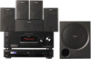
3-093-550-11 (1) DVD Home Theatre System Operating Instructions Owner's Record The model and serial numbers are located on the rear of the unit. Model No. Refer to them whenever you call upon your Sony dealer regarding this product. HT-7100DH ©2007 Sony Corporation Serial No. Record the serial number in the space provided below.
3-093-550-11 (1) DVD Home Theatre System Operating Instructions Owner's Record The model and serial numbers are located on the rear of the unit. Model No. Refer to them whenever you call upon your Sony dealer regarding this product. HT-7100DH ©2007 Sony Corporation Serial No. Record the serial number in the space provided below.
Operating Instructions
Page 2
... harmful interference to radio or television reception, which can be unplugged from that to which the receiver is provided to call CATV system installer's attention to the point of cable entry as chemical waste. This equipment generates, uses, and can be determined by one... Don't throw away batteries with the limits for help. For customers in accordance with newspapers, table-cloths, curtains, etc. If this system so that the cable ground shall be of sufficient magnitude to constitute a risk of electric shock to correct the interference by turning the equipment...
... harmful interference to radio or television reception, which can be unplugged from that to which the receiver is provided to call CATV system installer's attention to the point of cable entry as chemical waste. This equipment generates, uses, and can be determined by one... Don't throw away batteries with the limits for help. For customers in accordance with newspapers, table-cloths, curtains, etc. If this system so that the cable ground shall be of sufficient magnitude to constitute a risk of electric shock to correct the interference by turning the equipment...
Operating Instructions
Page 3
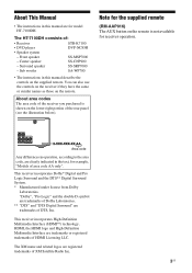
... code AA only". About area codes The area code of the receiver you purchased is shown on the remote is not available for model HT-7100DH. You can also use the controls on the receiver if they have the same or similar names as those on the supplied remote. Note...supplied remote (RM-AAP016) The AUX button on the lower right portion of : • Receiver STR-K7100 • DVD player DVP-NC85H • Speaker system - The HT-7100DH consists of the rear panel (see the illustration below). About This Manual • The instructions in this manual describe the controls on the remote.
... code AA only". About area codes The area code of the receiver you purchased is shown on the remote is not available for model HT-7100DH. You can also use the controls on the receiver if they have the same or similar names as those on the supplied remote. Note...supplied remote (RM-AAP016) The AUX button on the lower right portion of : • Receiver STR-K7100 • DVD player DVP-NC85H • Speaker system - The HT-7100DH consists of the rear panel (see the illustration below). About This Manual • The instructions in this manual describe the controls on the remote.
Operating Instructions
Page 4
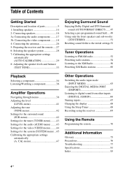
...Installing speakers 14 2: Connecting speakers 16 3a: Connecting the audio components ........17 3b: Connecting the video components ........18 4: Connecting the antennas 26 5: Preparing the receiver and the remote.....27 6: Selecting the speaker system 28 7: Calibrating the appropriate settings automatically (AUTO CALIBRATION 29 ... PORT (DMPORT 63 Listening to the XM Radio 56 Presetting XM Radio stations 60 Playback Selecting a component 34 Listening/Watching a component 36 Amplifier Operations Navigating through menus 38 Adjusting the level (LEVEL menu 41 Adjusting the tone (TONE...
...Installing speakers 14 2: Connecting speakers 16 3a: Connecting the audio components ........17 3b: Connecting the video components ........18 4: Connecting the antennas 26 5: Preparing the receiver and the remote.....27 6: Selecting the speaker system 28 7: Calibrating the appropriate settings automatically (AUTO CALIBRATION 29 ... PORT (DMPORT 63 Listening to the XM Radio 56 Presetting XM Radio stations 60 Playback Selecting a component 34 Listening/Watching a component 36 Amplifier Operations Navigating through menus 38 Adjusting the level (LEVEL menu 41 Adjusting the tone (TONE...

Operating Instructions
Page 5
The current status of the selected component or a list of all speakers at the same time (page 33, 34, 36, 37). Receives signals from remote ...the display (page 68). Press to both digital and analog jacks (page 63). Press to select the input mode when the same components are connected to activate the Auto Calibration function (page 29). Press to mute the sound (page 34). continued 5US MOVIE MUSIC AUTO... CHANNEL DECODING DISPLAY INPUT MODE INPUT SELECTOR MASTER VOLUME MEMORY/ ENTER TUNING MODE TUNING 2CH A.F.D. Press to select the speaker system (page 28).
The current status of the selected component or a list of all speakers at the same time (page 33, 34, 36, 37). Receives signals from remote ...the display (page 68). Press to both digital and analog jacks (page 63). Press to select the input mode when the same components are connected to activate the Auto Calibration function (page 29). Press to mute the sound (page 34). continued 5US MOVIE MUSIC AUTO... CHANNEL DECODING DISPLAY INPUT MODE INPUT SELECTOR MASTER VOLUME MEMORY/ ENTER TUNING MODE TUNING 2CH A.F.D. Press to select the speaker system (page 28).

Operating Instructions
Page 6
Name Function K INPUT SELECTOR Turn to select the input source to store a station or enter the selection when selecting the settings (page 27). O TUNING +/- Q MEMORY/ENTER Press to playback (page 34, 36, 37, 53, 55, 63, 65, 69). M A.F.D. jacks S AUTO CAL MIC jack Connects to camcorder or PORTABLE AV IN video game (page 25, 34). mode (page 47). R VIDEO 3 IN/ Connect to the supplied optimizer microphone for the Auto Calibration function (page 29). T PHONES jack Connects to select the tuning mode (page 55, 81). P TUNING MODE Press to a headphone (page 78). 6US ...
Name Function K INPUT SELECTOR Turn to select the input source to store a station or enter the selection when selecting the settings (page 27). O TUNING +/- Q MEMORY/ENTER Press to playback (page 34, 36, 37, 53, 55, 63, 65, 69). M A.F.D. jacks S AUTO CAL MIC jack Connects to camcorder or PORTABLE AV IN video game (page 25, 34). mode (page 47). R VIDEO 3 IN/ Connect to the supplied optimizer microphone for the Auto Calibration function (page 29). T PHONES jack Connects to select the tuning mode (page 55, 81). P TUNING MODE Press to a headphone (page 78). 6US ...
Operating Instructions
Page 7
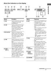
... VIDEO 2 input is activated (page 41). Name F OPT G DTS H Tuner indicators I Preset station indicators J D.RANGE Function Lights up when using the receiver to the speaker system used. For details on the display if no digital signal is a digital signal being reproduced. INPUT MODE is not set to "ANALOG" (page 63). PL...
... VIDEO 2 input is activated (page 41). Name F OPT G DTS H Tuner indicators I Preset station indicators J D.RANGE Function Lights up when using the receiver to the speaker system used. For details on the display if no digital signal is a digital signal being reproduced. INPUT MODE is not set to "ANALOG" (page 63). PL...

Operating Instructions
Page 8
... boxes around the letters vary to "COAX IN" (page 63). Front Left Front Right Center (monaural) Surround Left Surround Right Surround (monaural or the surround components obtained by Pro Logic processing) Example: Recording format (Front/ Surround): 3/2.1 Sound Field: A.F.D. Lights up when a memory function, such as Preset Memory (page 54), etc., is...
... boxes around the letters vary to "COAX IN" (page 63). Front Left Front Right Center (monaural) Surround Left Surround Right Surround (monaural or the surround components obtained by Pro Logic processing) Example: Recording format (Front/ Surround): 3/2.1 Sound Field: A.F.D. Lights up when a memory function, such as Preset Memory (page 54), etc., is...
Operating Instructions
Page 9
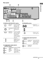
... TV or a projector (page 22). The image and the sound are output to a DVD player, or a Blu-ray disc player. B COMPONENT VIDEO INPUT/ OUTPUT section Green Blue Red COMPONENT Connects to sub woofer (page 16). Connects to a DVD VIDEO player, TV, INPUT/ satellite tuner, etc. continued 9US Getting Started Rear panel... HDMI Y XM PB/CB PR/CR VIDEO IN VIDEO IN VIDEO OUT VIDEO IN VIDEO OUT SAT IN DVD IN VIDEO 1 IN MONITOR OUT L MONITOR COMPONENT VIDEO R L L L L L AUDIO OUT R R OUT IN IN SA-CD/CD/CD-R TV R AUDIO IN AUDIO IN SAT DVD R AUDIO OUT AUDIO IN VIDEO 1 SUB ...
... TV or a projector (page 22). The image and the sound are output to a DVD player, or a Blu-ray disc player. B COMPONENT VIDEO INPUT/ OUTPUT section Green Blue Red COMPONENT Connects to sub woofer (page 16). Connects to a DVD VIDEO player, TV, INPUT/ satellite tuner, etc. continued 9US Getting Started Rear panel... HDMI Y XM PB/CB PR/CR VIDEO IN VIDEO IN VIDEO OUT VIDEO IN VIDEO OUT SAT IN DVD IN VIDEO 1 IN MONITOR OUT L MONITOR COMPONENT VIDEO R L L L L L AUDIO OUT R R OUT IN IN SA-CD/CD/CD-R TV R AUDIO IN AUDIO IN SAT DVD R AUDIO OUT AUDIO IN VIDEO 1 SUB ...
Operating Instructions
Page 10
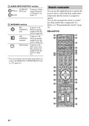
AM ANTENNA terminals Connects to the AM loop antenna supplied with this receiver) (page 57). RM-AAP016 wj wh TV RM SET UP AV ?/1 ? / 1 SYSTEM STANDBY VIDEO 1 VIDEO 2 VIDEO 3 DVD SAT TV SA-CD/CD TUNER 1 2 3 AUX DMPORT RECEIVER 4 2CH A.F.D. TUNING + m M DISC SKIP TV VOL .... (page 17). Remote commander You can watch the selected input image when you connect the HDMI OUT or MONITOR OUT jack to control non-Sony audio/video components. For details, see "Programming the remote" (page 70). E AUDIO INPUT/OUTPUT section AUDIO IN/ White (L) OUT jack Red (R) Connects to ...
AM ANTENNA terminals Connects to the AM loop antenna supplied with this receiver) (page 57). RM-AAP016 wj wh TV RM SET UP AV ?/1 ? / 1 SYSTEM STANDBY VIDEO 1 VIDEO 2 VIDEO 3 DVD SAT TV SA-CD/CD TUNER 1 2 3 AUX DMPORT RECEIVER 4 2CH A.F.D. TUNING + m M DISC SKIP TV VOL .... (page 17). Remote commander You can watch the selected input image when you connect the HDMI OUT or MONITOR OUT jack to control non-Sony audio/video components. For details, see "Programming the remote" (page 70). E AUDIO INPUT/OUTPUT section AUDIO IN/ White (L) OUT jack Red (R) Connects to ...
Operating Instructions
Page 11
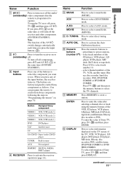
...time, it will turn off the receiver and other components (SYSTEM STANDBY). MOVIE F D. ray disc recorder, hard disc recorder, PSX, DVD/VHS COMBO or DVD/HDD COMBO. Press TV (Z) and then press the numeric buttons to control Sony components as follows. ENTER Press to enter the value after ...any of the AV ?/1 switch changes automatically each time you press ?/1 (B) at the same time (SYSTEM STANDBY). You can program the remote to control non-Sony components following the steps in tuner AUX Not assigned DMPORT DIGITAL MEDIA PORT adapter Press to activate the Auto ...
...time, it will turn off the receiver and other components (SYSTEM STANDBY). MOVIE F D. ray disc recorder, hard disc recorder, PSX, DVD/VHS COMBO or DVD/HDD COMBO. Press TV (Z) and then press the numeric buttons to control Sony components as follows. ENTER Press to enter the value after ...any of the AV ?/1 switch changes automatically each time you press ?/1 (B) at the same time (SYSTEM STANDBY). You can program the remote to control non-Sony components following the steps in tuner AUX Not assigned DMPORT DIGITAL MEDIA PORT adapter Press to activate the Auto ...
Operating Instructions
Page 12
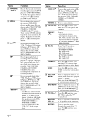
...player, DVD player, MD deck, DAT deck, tape deck, Blu-ray disc recorder, PSX, DVD/VHS COMBO or DVD/ HDD COMBO. select preset channels of Sony TV, press TV (Z) and then press MENU. Then, use the V/v/B/b and to perform menu operations. Press TV (Z) and then press TV VOL to select ... speakers at the same time. to display the menus of the DVD player on the TV screen. O F1, F2 Press F1 or F2 to select a component to adjust the volume level VOL +/- Q TV VOL +/- MASTER Press to operate. - Then, use the V/v/B/b and to perform menu operations. TUNING +/- Press TV (Z) and ...
...player, DVD player, MD deck, DAT deck, tape deck, Blu-ray disc recorder, PSX, DVD/VHS COMBO or DVD/ HDD COMBO. select preset channels of Sony TV, press TV (Z) and then press MENU. Then, use the V/v/B/b and to perform menu operations. Press TV (Z) and then press TV VOL to select ... speakers at the same time. to display the menus of the DVD player on the TV screen. O F1, F2 Press F1 or F2 to select a component to adjust the volume level VOL +/- Q TV VOL +/- MASTER Press to operate. - Then, use the V/v/B/b and to perform menu operations. TUNING +/- Press TV (Z) and ...
Operating Instructions
Page 13
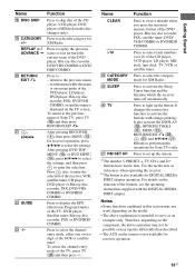
.... Press to activate the buttons with the DIGITAL MEDIA PORT adapter. a)The number 5, PRESET +, TV CH + and H buttons have tactile dots. Therefore, depending on the component, the above operation may not be possible or may not work depending on the model. • The above explanation is displayed on the remote is... channel entry mode of the CD player, VCD player, LD player, MD deck, tape deck, TV, VCR or satellite tuner. Press to skip disc of Sony TV, press TV (Z) and then press RETURN/EXIT O. For details on -screen guide of the VCD player, LD player, DVD player, Blu-ray disc ...
.... Press to activate the buttons with the DIGITAL MEDIA PORT adapter. a)The number 5, PRESET +, TV CH + and H buttons have tactile dots. Therefore, depending on the component, the above operation may not be possible or may not work depending on the model. • The above explanation is displayed on the remote is... channel entry mode of the CD player, VCD player, LD player, MD deck, tape deck, TV, VCR or satellite tuner. Press to skip disc of Sony TV, press TV (Z) and then press RETURN/EXIT O. For details on -screen guide of the VCD player, LD player, DVD player, Blu-ray disc ...

Operating Instructions
Page 14
1: Installing speakers To fully enjoy theater-like multi channel surround sound requires five speakers (two front speakers, a center speaker, and two surround speakers) and a sub woofer (5.1 channel). Installing the speakers on a ... and sub woofer, be sure to attach the supplied foot pads to prevent vibration or movement as shown in certain countries). Example of a 5.1 channel speaker system configuration Installing the speakers on the speaker stand For greater flexibility in positioning the speakers, use the optional WS-FV11 speaker stand (available only in...
1: Installing speakers To fully enjoy theater-like multi channel surround sound requires five speakers (two front speakers, a center speaker, and two surround speakers) and a sub woofer (5.1 channel). Installing the speakers on a ... and sub woofer, be sure to attach the supplied foot pads to prevent vibration or movement as shown in certain countries). Example of a 5.1 channel speaker system configuration Installing the speakers on the speaker stand For greater flexibility in positioning the speakers, use the optional WS-FV11 speaker stand (available only in...

Operating Instructions
Page 15
... on a vertical and flat wall where reinforcement is applied. • Contact a screw shop or installer regarding the wall material or screws to be used. • Sony is especially fragile, attach the screws securely to a beam and fasten them to the wall. Install the speakers on the screws. Getting Started Installing the...
... on a vertical and flat wall where reinforcement is applied. • Contact a screw shop or installer regarding the wall material or screws to be used. • Sony is especially fragile, attach the screws securely to a beam and fasten them to the wall. Install the speakers on the screws. Getting Started Installing the...
Operating Instructions
Page 16
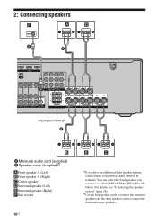
... HDMI Y XM PB/CB PR/CR VIDEO IN VIDEO IN VIDEO OUT VIDEO IN VIDEO OUT SAT IN DVD IN VIDEO 1 IN MONITOR OUT L MONITOR COMPONENT VIDEO R L L L AUDIO OUT R AUDIO IN AUDIO IN SAT DVD R AUDIO OUT AUDIO IN VIDEO 1 SUB WOOFER FRONT B R FRONT A SPEAKERS L R SURROUND CENTER SPEAKERS FRONT Ba) B B A Monaural... the long speaker cords to connect the surround speakers and the short speaker cords to the SPEAKERS FRONT B terminal. For details, see "6: Selecting the speaker system" (page 28). You can select the front speakers you have an additional front speaker...
... HDMI Y XM PB/CB PR/CR VIDEO IN VIDEO IN VIDEO OUT VIDEO IN VIDEO OUT SAT IN DVD IN VIDEO 1 IN MONITOR OUT L MONITOR COMPONENT VIDEO R L L L AUDIO OUT R AUDIO IN AUDIO IN SAT DVD R AUDIO OUT AUDIO IN VIDEO 1 SUB WOOFER FRONT B R FRONT A SPEAKERS L R SURROUND CENTER SPEAKERS FRONT Ba) B B A Monaural... the long speaker cords to connect the surround speakers and the short speaker cords to the SPEAKERS FRONT B terminal. For details, see "6: Selecting the speaker system" (page 28). You can select the front speakers you have an additional front speaker...
Operating Instructions
Page 17
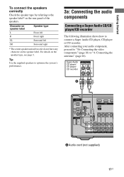
After connecting your audio component, proceed to connect a Super Audio CD player, CD player or CD recorder. For details on the speaker label. Tip Use the supplied speakers to optimize the system's performance. 3a: Connecting the audio components Connecting a Super Audio CD/CD player/CD ...recorder The following illustration shows how to "3b: Connecting the video components" (page 18) or "4: Connecting the antennas" (page 26)....
After connecting your audio component, proceed to connect a Super Audio CD player, CD player or CD recorder. For details on the speaker label. Tip Use the supplied speakers to optimize the system's performance. 3a: Connecting the audio components Connecting a Super Audio CD/CD player/CD ...recorder The following illustration shows how to "3b: Connecting the video components" (page 18) or "4: Connecting the antennas" (page 26)....
Operating Instructions
Page 18
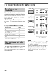
...MEMORY/ ENTER TUNING MODE TUNING 2CH A.F.D. MOVIE MUSIC AUTO CAL MUTING Receiver INPUT jack Video component OUTPUT jack HDMI HDMI COMPONENT VIDEO VIDEO COMPONENT VIDEO VIDEO High quality image Notes • Connect image display components such as a TV or a projector to the HDMI OUT or MONITOR OUT jack on...on , neither video nor audio is not on the receiver when the video and audio of the receiver is transmitted. 18US Component to be connected Component Page TV 19 DVD player/DVD recorder 20 With HDMI jack 22 Satellite tuner/Set-top box 24 VCR 25 Camcorder, video...
...MEMORY/ ENTER TUNING MODE TUNING 2CH A.F.D. MOVIE MUSIC AUTO CAL MUTING Receiver INPUT jack Video component OUTPUT jack HDMI HDMI COMPONENT VIDEO VIDEO COMPONENT VIDEO VIDEO High quality image Notes • Connect image display components such as a TV or a projector to the HDMI OUT or MONITOR OUT jack on...on , neither video nor audio is not on the receiver when the video and audio of the receiver is transmitted. 18US Component to be connected Component Page TV 19 DVD player/DVD recorder 20 With HDMI jack 22 Satellite tuner/Set-top box 24 VCR 25 Camcorder, video...