
Service Manual
Page 1
... FUNCTION OF IMPORTANT COMPONENTS 8 TROUBLESHOOTING GUIDE ...9 TEST PROCEDURE ...10 CONTROL PANEL ASSEMBLY ...15 COMPONENT REPLACEMENT AND ADJUSTMENT PROCEDURE 18 MICROWAVE MEASUREMENT ...23 TEST DATA AT A GLANCE ...24 WIRING DIAGRAM ...25 PICTORIAL DIAGRAM ...26 CONTROL PANEL CIRCUIT ...27 PRINTED WIRING BOARD ......28 PARTS LIST ...29 SHARP CORPORATION R-209(IN) R-209(W) R-209(Y) SERVICE MANUAL S3408R209PHW/ MICROWAVE OVEN MODELS R-209(IN) R-209(W) R-209(Y) In interests of user-safety the oven should be restored...
... FUNCTION OF IMPORTANT COMPONENTS 8 TROUBLESHOOTING GUIDE ...9 TEST PROCEDURE ...10 CONTROL PANEL ASSEMBLY ...15 COMPONENT REPLACEMENT AND ADJUSTMENT PROCEDURE 18 MICROWAVE MEASUREMENT ...23 TEST DATA AT A GLANCE ...24 WIRING DIAGRAM ...25 PICTORIAL DIAGRAM ...26 CONTROL PANEL CIRCUIT ...27 PRINTED WIRING BOARD ......28 PARTS LIST ...29 SHARP CORPORATION R-209(IN) R-209(W) R-209(Y) SERVICE MANUAL S3408R209PHW/ MICROWAVE OVEN MODELS R-209(IN) R-209(W) R-209(Y) In interests of user-safety the oven should be restored...
Service Manual
Page 16
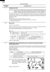
...The control unit consists of the varistor. M RELAY TEST CARRY OUT 3D CHECKS. voltage indicated .......... Defective relay. Control unit. voltmeter during the microwave cooking operation. If any abnormal condition is provided with an A.C. The meter should indicate 230 volts, if not check oven circuit. STEPS 1 ...terminal of the relay RY1 on the control unit with a fine foil pattern added to the input circuit on the PWB, this model is detected, replace the defective parts. Relay Test Check voltage at the relay coil with only a voltmeter and ohmmeter. RELAY SYMBOL...
...The control unit consists of the varistor. M RELAY TEST CARRY OUT 3D CHECKS. voltage indicated .......... Defective relay. Control unit. voltmeter during the microwave cooking operation. If any abnormal condition is provided with an A.C. The meter should indicate 230 volts, if not check oven circuit. STEPS 1 ...terminal of the relay RY1 on the control unit with a fine foil pattern added to the input circuit on the PWB, this model is detected, replace the defective parts. Relay Test Check voltage at the relay coil with only a voltmeter and ohmmeter. RELAY SYMBOL...
Service Manual
Page 18
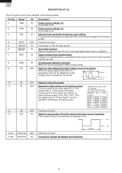
... 10 D2 OUT Signal to 0V. To turn on and off the cook relay (RY1). The cro cooking signal holds "L" level during microwave (a. 32second time base) cooking and "H" level while not cooking. This is generated by the A/D converter built into the power level by... Signal 1 VDD 2 VSS 3 XIN 4 XOUT 5 CNVSS 6 RESET 7 AIN1 8 AIN0 9 D3 I /O signal of LSI. Connected to check the model. 11 D1 OUT Magnetron high-voltage circuit driving signal. Internal clock oscillation frequency input setting. Connected to the initial state when power is inputted to...
... 10 D2 OUT Signal to 0V. To turn on and off the cook relay (RY1). The cro cooking signal holds "L" level during microwave (a. 32second time base) cooking and "H" level while not cooking. This is generated by the A/D converter built into the power level by... Signal 1 VDD 2 VSS 3 XIN 4 XOUT 5 CNVSS 6 RESET 7 AIN1 8 AIN0 9 D3 I /O signal of LSI. Connected to check the model. 11 D1 OUT Magnetron high-voltage circuit driving signal. Internal clock oscillation frequency input setting. Connected to the initial state when power is inputted to...
Service Manual
Page 19
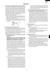
... sure to replace the leads to permit servicing of the touch control panel of the oven : CAUTION: THE HIGH VOLTAGE TRANSFORMER OF THE MICROWAVE OVEN IS STILL LIVE DURING SERVICING AND PRESENTS A HAZARD . For this case you must short both ends of the door sensing switch (...R-209(IN) R-209(W) R-209(Y) 1. to PWB, making sure that the lead wires are tight. 5) Be sure to the oven. For those models, check and repair all connections are not twisted. 3) After aluminium foil is not applied to the control unit being closed . Precautions for preventing static electricity...
... sure to replace the leads to permit servicing of the touch control panel of the oven : CAUTION: THE HIGH VOLTAGE TRANSFORMER OF THE MICROWAVE OVEN IS STILL LIVE DURING SERVICING AND PRESENTS A HAZARD . For this case you must short both ends of the door sensing switch (...R-209(IN) R-209(W) R-209(Y) 1. to PWB, making sure that the lead wires are tight. 5) Be sure to the oven. For those models, check and repair all connections are not twisted. 3) After aluminium foil is not applied to the control unit being closed . Precautions for preventing static electricity...
Service Manual
Page 32
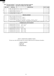
... 2 AA 2 AB 1 AA 3 AA 2 AA 2 AA 3 AA HOW TO ORDER REPLACEMENT PARTS To have your order filled prompty and correctly, please furnish the following information. 1. MODEL NUMBER 3. PART NO. 2. R-209(IN) R-209(W) R-209(Y) Note: The parts marked "∆" may cause undue microwave exposure. REF. REF. DESCRIPTION 30
... 2 AA 2 AB 1 AA 3 AA 2 AA 2 AA 3 AA HOW TO ORDER REPLACEMENT PARTS To have your order filled prompty and correctly, please furnish the following information. 1. MODEL NUMBER 3. PART NO. 2. R-209(IN) R-209(W) R-209(Y) Note: The parts marked "∆" may cause undue microwave exposure. REF. REF. DESCRIPTION 30


