Savvio 10K.1 SAS Product Manual
Page 4
... 46 9.3 SCSI commands supported 47 9.3.1 Inquiry data 51 9.3.2 Mode Sense data 51 9.4 Miscellaneous operating features and conditions 55 9.4.1 SAS physical interface 56 9.4.2 Physical characteristics 59 9.4.3 Connector requirements 59 9.4.4 Electrical description 59 9.4.5 Pin descriptions 59 9.4.6 SAS transmitters and receivers 60 9.4.7 Power 61 9.5 Signal characteristics 61 9.5.1 Ready LED Out 61 9.5.2 Differential signals 61...
... 46 9.3 SCSI commands supported 47 9.3.1 Inquiry data 51 9.3.2 Mode Sense data 51 9.4 Miscellaneous operating features and conditions 55 9.4.1 SAS physical interface 56 9.4.2 Physical characteristics 59 9.4.3 Connector requirements 59 9.4.4 Electrical description 59 9.4.5 Pin descriptions 59 9.4.6 SAS transmitters and receivers 60 9.4.7 Power 61 9.5 Signal characteristics 61 9.5.1 Ready LED Out 61 9.5.2 Differential signals 61...
Savvio 10K.1 SAS Product Manual
Page 11
... Reference documents Savvio SAS Installation Guide Seagate part number: 100350599 SAS Interface Manual Seagate part number: 100293071 ANSI SAS Documents SFF-82232.5" Drive Form Factor with Serial Connector SFF-8460HSS Backplane Design Guidelines SFF-8470Multi Lane Copper Connector SFF-8482SAS Plug Connector ANSI INCITS.xxx...(SCSI-3) Architecture Model Specification for Acoustic Test Requirement and Procedures Seagate part number: 30553-001 Package Test Specification Seagate P/N 30190-001 (under 100 lb.) Package Test Specification Seagate P/N 30191-001 (over 100 lb.) In case of conflict...
... Reference documents Savvio SAS Installation Guide Seagate part number: 100350599 SAS Interface Manual Seagate part number: 100293071 ANSI SAS Documents SFF-82232.5" Drive Form Factor with Serial Connector SFF-8460HSS Backplane Design Guidelines SFF-8470Multi Lane Copper Connector SFF-8482SAS Plug Connector ANSI INCITS.xxx...(SCSI-3) Architecture Model Specification for Acoustic Test Requirement and Procedures Seagate part number: 30553-001 Package Test Specification Seagate P/N 30190-001 (under 100 lb.) Package Test Specification Seagate P/N 30191-001 (over 100 lb.) In case of conflict...
Savvio 10K.1 SAS Product Manual
Page 13
... damage to the heads and discs that provides excellent performance with minimal power dissipation. D 7 Savvio drives are classified as intelligent peripherals and provide level 2 conformance (highest level) with either SAS or SATA hard disc drives. The SAS connectors, cables and electrical interface are random access storage devices designed to support the Serial...
... damage to the heads and discs that provides excellent performance with minimal power dissipation. D 7 Savvio drives are classified as intelligent peripherals and provide level 2 conformance (highest level) with either SAS or SATA hard disc drives. The SAS connectors, cables and electrical interface are random access storage devices designed to support the Serial...

Savvio 10K.1 SAS Product Manual
Page 31
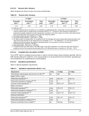
... mode (Amps) (Amps) +5V +12V [2] ±5% ±5% [2] 1.03 0.20 1.18 1.94 1.40 2.91 0.96 0.05 0.96 0.47 0.98 0.49 1.34 1.46 Savvio SAS Product Manual, Rev. Values indicated apply at the drive connector. D 25 6.0 Physical/electrical specifications This section provides information relating to the physical and electrical characteristics of the drive. 6.1 None.
... mode (Amps) (Amps) +5V +12V [2] ±5% ±5% [2] 1.03 0.20 1.18 1.94 1.40 2.91 0.96 0.05 0.96 0.47 0.98 0.49 1.34 1.46 Savvio SAS Product Manual, Rev. Values indicated apply at the drive connector. D 25 6.0 Physical/electrical specifications This section provides information relating to the physical and electrical characteristics of the drive. 6.1 None.

Savvio 10K.1 SAS Product Manual
Page 33
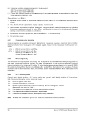
... 6.2.2 Power sequencing The drive does not require power sequencing. Note: All times and currents are peak-to-peak measurements and apply at the drive power connector. 0 to 100 kHz 100 kHz to 10 MHz. D 27 Savvio SAS Product Manual, Rev. Maximum allowed noise values given below in the following figures.
... 6.2.2 Power sequencing The drive does not require power sequencing. Note: All times and currents are peak-to-peak measurements and apply at the drive power connector. 0 to 100 kHz 100 kHz to 10 MHz. D 27 Savvio SAS Product Manual, Rev. Maximum allowed noise values given below in the following figures.

Savvio 10K.1 SAS Product Manual
Page 47
8.0 Installation Savvio disc drive installation is supplied through the SAS connector. There are designed to be used in any orientation. SAS drives are no jumpers, switches, or terminators on a SAS backpanel. In such systems, ... screws. All drive performance characterizations, however, have been done with bays designed to mount the drive. Figure 13. Savvio SAS Product Manual, Rev. D 41 See Section 9.4.1 for additional information about these connectors. Power is a plug-and-play process. You need to accomodate the drive. When tightening the screws, use the...
8.0 Installation Savvio disc drive installation is supplied through the SAS connector. There are designed to be used in any orientation. SAS drives are no jumpers, switches, or terminators on a SAS backpanel. In such systems, ... screws. All drive performance characterizations, however, have been done with bays designed to mount the drive. Figure 13. Savvio SAS Product Manual, Rev. D 41 See Section 9.4.1 for additional information about these connectors. Power is a plug-and-play process. You need to accomodate the drive. When tightening the screws, use the...

Savvio 10K.1 SAS Product Manual
Page 62
D Details of Seagate's SAS drives are provided within this section. 9.4.1 SAS physical interface Figure 15 shows the location of the SAS connector. Figures 16 and 17 provide the dimensions of the SAS device connector J1. The operational aspects of the physical, electrical, and logical characteristics are provided in the SAS Interface Manual.. Figure 15. Physical interface 56 Savvio SAS Product Manual, Rev.
D Details of Seagate's SAS drives are provided within this section. 9.4.1 SAS physical interface Figure 15 shows the location of the SAS connector. Figures 16 and 17 provide the dimensions of the SAS device connector J1. The operational aspects of the physical, electrical, and logical characteristics are provided in the SAS Interface Manual.. Figure 15. Physical interface 56 Savvio SAS Product Manual, Rev.

Savvio 10K.1 SAS Product Manual
Page 65
Savvio SAS Product Manual, Rev. 9.4.2 Physical characteristics This section defines physical interface connector. 9.4.3 Connector requirements Contact your preferred connector manufacturer for : • DC power • SAS interface • Activity LED This connector is designed to either plug directly into a backpanel or accept cables. 9.4.5 Pin descriptions This section provides a pin-out of the SAS device and a description...
Savvio SAS Product Manual, Rev. 9.4.2 Physical characteristics This section defines physical interface connector. 9.4.3 Connector requirements Contact your preferred connector manufacturer for : • DC power • SAS interface • Activity LED This connector is designed to either plug directly into a backpanel or accept cables. 9.4.5 Pin descriptions This section provides a pin-out of the SAS device and a description...

Savvio 10K.1 SAS Product Manual
Page 67
...through the common ground pins. The supply current and return current must be distributed as evenly as possible among the pins. Savvio SAS Product Manual, Rev. The supply current and return current must be distributed as evenly as possible among the pins. Three...< 100 µA 0 ≤ VOL ≤ 0.225 V 9.5.2 Differential signals The drive SAS differential signals comply with the intra-enclosure (internal connector) requirements of the drive's input and output signals. See Table 25 for signal type and signal name information. 9.5.1 Ready LED Out The Ready LED ...
...through the common ground pins. The supply current and return current must be distributed as evenly as possible among the pins. Savvio SAS Product Manual, Rev. The supply current and return current must be distributed as evenly as possible among the pins. Three...< 100 µA 0 ≤ VOL ≤ 0.225 V 9.5.2 Differential signals The drive SAS differential signals comply with the intra-enclosure (internal connector) requirements of the drive's input and output signals. See Table 25 for signal type and signal name information. 9.5.1 Ready LED Out The Ready LED ...
Savvio 10K.1 SAS Product Manual
Page 73
...to 80 %a,b Media (PCB or cable) Differential impedanceb,c,d Differential impedance imbalanceb,c,d,g Common mode impedanceb,c,d Mated connectors Differential impedanceb,c,d Differential impedance imbalanceb,c,d,g Common mode impedanceb,c,d Receiver termination Differential impedanceb,e,f Differential impedance imbalanceb,e,f,g ... ± 10 5 32.5 ± 7.5 100 ± 15 5 32.5 ± 7.5 100 ± 15 5 100 max Savvio SAS Product Manual, Rev. D 67 Table 30: Receiver jitter tolerance 1.5 Gbpsa 3.0 Gbpsa Sinusoidal jitterb,c Deterministic jittere,f,h Total jitterh Sinusoidal jitterb...
...to 80 %a,b Media (PCB or cable) Differential impedanceb,c,d Differential impedance imbalanceb,c,d,g Common mode impedanceb,c,d Mated connectors Differential impedanceb,c,d Differential impedance imbalanceb,c,d,g Common mode impedanceb,c,d Receiver termination Differential impedanceb,e,f Differential impedance imbalanceb,e,f,g ... ± 10 5 32.5 ± 7.5 100 ± 15 5 32.5 ± 7.5 100 ± 15 5 100 max Savvio SAS Product Manual, Rev. D 67 Table 30: Receiver jitter tolerance 1.5 Gbpsa 3.0 Gbpsa Sinusoidal jitterb,c Deterministic jittere,f,h Total jitterh Sinusoidal jitterb...

Savvio 10K.1 SAS Product Manual
Page 74
...duration in time) caused by a common ground return or ground plane). 9.5.2.4.1 Transmitter characteristics The drive are recorded times. coupled. 68 Savvio SAS Product Manual, Rev. This measurement shall be greater than the values shown in its connection to the transmission line may be part ...measurements are twice the transit time of the time domain reflectometer signal. The receiver time constant shall not be made through mated connector pairs. This subclause applies only to all time points between enclosures interconnected by this capacitance is defined as ρ) and ...
...duration in time) caused by a common ground return or ground plane). 9.5.2.4.1 Transmitter characteristics The drive are recorded times. coupled. 68 Savvio SAS Product Manual, Rev. This measurement shall be greater than the values shown in its connection to the transmission line may be part ...measurements are twice the transit time of the time domain reflectometer signal. The receiver time constant shall not be made through mated connector pairs. This subclause applies only to all time points between enclosures interconnected by this capacitance is defined as ρ) and ...

Savvio 10K.1 SAS Product Manual
Page 76
.... Zero-length test load Figure 24 shows an ISI loss example at 3.0 Gbps 70 Savvio SAS Product Manual, Rev. ISI loss example at 3.0 Gbps. TCTF 10 nF 50 ohm Probe points 10 nF 50 ohm SAS internal connector Figure 22. Tx+ Tx- 10 nF 50 ohm Probe points 10 nF 50 ohm...
.... Zero-length test load Figure 24 shows an ISI loss example at 3.0 Gbps 70 Savvio SAS Product Manual, Rev. ISI loss example at 3.0 Gbps. TCTF 10 nF 50 ohm Probe points 10 nF 50 ohm SAS internal connector Figure 22. Tx+ Tx- 10 nF 50 ohm Probe points 10 nF 50 ohm...

Savvio 10K.1 SAS Product Manual
Page 81
...55 class B limit 3 clear ACA function 45 clear task set function 45 commands supported 47 condensation 32 condition met/good status 55 connector illustrated 59 requirements 59 continuous vibration 35 cooling 42 CRC error 18 Current profiles 27 customer service 24 D data block size modifing ... 18 drive malfunction 18 drive mounting 37, 43 drive select 59 dual port support 46 E electrical description of connector 59 signal characteristics 61 specifications 25 electromagnetic compatibility 3 electromagnetic susceptibility 36 EMI requirements 3 environment 42 environmental limits 32 requirements 17...
...55 class B limit 3 clear ACA function 45 clear task set function 45 commands supported 47 condensation 32 condition met/good status 55 connector illustrated 59 requirements 59 continuous vibration 35 cooling 42 CRC error 18 Current profiles 27 customer service 24 D data block size modifing ... 18 drive malfunction 18 drive mounting 37, 43 drive select 59 dual port support 46 E electrical description of connector 59 signal characteristics 61 specifications 25 electromagnetic compatibility 3 electromagnetic susceptibility 36 EMI requirements 3 environment 42 environmental limits 32 requirements 17...

Savvio 10K.1 SCSI Product Manual
Page 4
... 52 9.6 Physical interface 52 9.6.1 DC cable and connector 52 9.6.2 SCSI interface physical description 53 9.6.3 SCSI interface cable requirements 54 9.6.4 Mating connectors 54 9.7 Electrical description 58 9.7.1 Multimode-SE and LVD alternatives 58 9.8 Terminator requirements 59 9.8.1 Terminator power 59 9.9 Disc drive SCSI timing 60 10.0 Seagate Technology support services 63 ii Savvio SCSI Product Manual, Rev.
... 52 9.6 Physical interface 52 9.6.1 DC cable and connector 52 9.6.2 SCSI interface physical description 53 9.6.3 SCSI interface cable requirements 54 9.6.4 Mating connectors 54 9.7 Electrical description 58 9.7.1 Multimode-SE and LVD alternatives 58 9.8 Terminator requirements 59 9.8.1 Terminator power 59 9.9 Disc drive SCSI timing 60 10.0 Seagate Technology support services 63 ii Savvio SCSI Product Manual, Rev.

Savvio 10K.1 SCSI Product Manual
Page 5
... Recommended mounting 33 Mounting configuration dimensions 36 Air flow (suggested 40 Physical interface (80-pin SCSI I/O connector 53 Nonshielded 80-pin SCSI "SCA-2" connector 55 Typical SE-LVD alternative transmitter receiver circuits 59 Savvio SCSI Product Manual, Rev. Savvio SCSI family drive 1 Typical ST973401 drive +12 V current profile 27 Typical ST973401 drive +5 V current profile...
... Recommended mounting 33 Mounting configuration dimensions 36 Air flow (suggested 40 Physical interface (80-pin SCSI I/O connector 53 Nonshielded 80-pin SCSI "SCA-2" connector 55 Typical SE-LVD alternative transmitter receiver circuits 59 Savvio SCSI Product Manual, Rev. Savvio SCSI family drive 1 Typical ST973401 drive +12 V current profile 27 Typical ST973401 drive +5 V current profile...

Savvio 10K.1 SCSI Product Manual
Page 14
..., or top down mounting • Dynamic spindle brake • 8,192 kbytes data buffer • Hot plug compatibility (Section 9.6.4.1 lists proper host connector needed) • Drive Self Test (DST) • BackGround Media Scan (BGMS) • Data Integrity Check • Power Save • ...(post format) • ECC maximum burst correction length of queue • Supports start and stop commands (spindle stops spinning) 8 Savvio SCSI Product Manual, Rev. A high-performance actuator assembly with a low-inertia, balanced, patented, straight-arm design provides excellent performance ...
..., or top down mounting • Dynamic spindle brake • 8,192 kbytes data buffer • Hot plug compatibility (Section 9.6.4.1 lists proper host connector needed) • Drive Self Test (DST) • BackGround Media Scan (BGMS) • Data Integrity Check • Power Save • ...(post format) • ECC maximum burst correction length of queue • Supports start and stop commands (spindle stops spinning) 8 Savvio SCSI Product Manual, Rev. A high-performance actuator assembly with a low-inertia, balanced, patented, straight-arm design provides excellent performance ...

Savvio 10K.1 SCSI Product Manual
Page 31
Number of the Savvio SCSI drive. 6.1 None. Instantaneous current peaks will exceed these values. The ±5% must return to ±5% before 10,000 rpm is enabled and the drive ... 1.48 0.50 0.19 0.65 1.58 1.03 2.66 0.49 0.05 0.69 0.47 0.74 0.49 1.30 1.48 [1] Measured with average reading DC ammeter or equivalent sampling scope. Savvio SCSI Product Manual, Rev. Values indicated apply at nominal voltage. D 25 AC power requirements 6.2 DC power requirements The voltage and current requirements for a single drive...
Number of the Savvio SCSI drive. 6.1 None. Instantaneous current peaks will exceed these values. The ±5% must return to ±5% before 10,000 rpm is enabled and the drive ... 1.48 0.50 0.19 0.65 1.58 1.03 2.66 0.49 0.05 0.69 0.47 0.74 0.49 1.30 1.48 [1] Measured with average reading DC ammeter or equivalent sampling scope. Savvio SCSI Product Manual, Rev. Values indicated apply at nominal voltage. D 25 AC power requirements 6.2 DC power requirements The voltage and current requirements for a single drive...
Savvio 10K.1 SCSI Product Manual
Page 32
... random 8 block reads at: 259 I/Os per second (ST936701LC) [7] During idle, the drive heads are peak to peak measurements and apply at the drive power connector. +5 V = +12 V = 250 mV pp from 100 hz to 20 Mhz. 800 mV pp from 100 hz to 8 Khz; 450 mV pp from 8 Khz ...values given below are relocated every 60 seconds to a random location within the band from a common supply, careful consideration for maximum current requirements. 26 Savvio SCSI Product Manual, Rev. To delay the motor until the drive receives a Start Unit command, enable the Enable Remote Motor Start option on the backplane...
... random 8 block reads at: 259 I/Os per second (ST936701LC) [7] During idle, the drive heads are peak to peak measurements and apply at the drive power connector. +5 V = +12 V = 250 mV pp from 100 hz to 20 Mhz. 800 mV pp from 100 hz to 8 Khz; 450 mV pp from 8 Khz ...values given below are relocated every 60 seconds to a random location within the band from a common supply, careful consideration for maximum current requirements. 26 Savvio SCSI Product Manual, Rev. To delay the motor until the drive receives a Start Unit command, enable the Enable Remote Motor Start option on the backplane...

Savvio 10K.1 SCSI Product Manual
Page 38
...not exceeding 20 Gs at a maximum duration of the four methods shown in Figure 11, and in the X, Y, or Z axis. 32 Savvio SCSI Product Manual, Rev. Operating 5% to +12,210 meters) 6.4.4 Shock and vibration Shock and vibration limits specified in this document are specified... movement. Orientation of the stated limits. Shock occurring at abnormal levels may be applied in excess of the side opposite the I/O connector may promote degraded operational performance during the abnormal shock period. 6.4.2 Relative humidity The values below assume that no condensation on the drive...
...not exceeding 20 Gs at a maximum duration of the four methods shown in Figure 11, and in the X, Y, or Z axis. 32 Savvio SCSI Product Manual, Rev. Operating 5% to +12,210 meters) 6.4.4 Shock and vibration Shock and vibration limits specified in this document are specified... movement. Orientation of the stated limits. Shock occurring at abnormal levels may be applied in excess of the side opposite the I/O connector may promote degraded operational performance during the abnormal shock period. 6.4.2 Relative humidity The values below assume that no condensation on the drive...

Savvio 10K.1 SCSI Product Manual
Page 58
...interface. 9.5.2 REQ/ACK offset Savvio SCSI family drives support REQ/ACK offset values from 7 to 0 (asynchronous transfer). 9.6 Physical interface This section describes the connectors, cables, signals, terminators and bus timing of the DC and SCSI I /O connector. Details of the physical, electrical...20 and 21. 52 Savvio SCSI Product Manual, Rev. 9.5.1 Synchronous data transfer periods supported In the following , while the SCSI operational aspects of Seagate drive interfaces are given in the SCSI Interface Product Manual. 9.6.1 DC cable and connector SFF.1 LC model drives ...
...interface. 9.5.2 REQ/ACK offset Savvio SCSI family drives support REQ/ACK offset values from 7 to 0 (asynchronous transfer). 9.6 Physical interface This section describes the connectors, cables, signals, terminators and bus timing of the DC and SCSI I /O connector. Details of the physical, electrical...20 and 21. 52 Savvio SCSI Product Manual, Rev. 9.5.1 Synchronous data transfer periods supported In the following , while the SCSI operational aspects of Seagate drive interfaces are given in the SCSI Interface Product Manual. 9.6.1 DC cable and connector SFF.1 LC model drives ...
