Momentus 7200.4 SATA Product Manual
Page 3
...environment 16 3.0 Configuring and mounting the drive 19 3.1 Handling and static-discharge precautions 19 3.2 Configuring the drive 20 3.3 Serial ATA cables and connectors 20 3.4 Drive mounting 21 4.0 Serial ATA ...(SATA) interface 23 4.1 Hot-Plug compatibility 23 4.2 Serial ATA device plug connector pin definitions 23 4.3 Supported ATA commands 25 4.3.1 Identify Device command 27 4.3.2 Set Features command 31 4.3.3 S.M.A.R.T. commands 32 5.0 Seagate Technology support services 33 Momentus 7200...
...environment 16 3.0 Configuring and mounting the drive 19 3.1 Handling and static-discharge precautions 19 3.2 Configuring the drive 20 3.3 Serial ATA cables and connectors 20 3.4 Drive mounting 21 4.0 Serial ATA ...(SATA) interface 23 4.1 Hot-Plug compatibility 23 4.2 Serial ATA device plug connector pin definitions 23 4.3 Supported ATA commands 25 4.3.1 Identify Device command 27 4.3.2 Set Features command 31 4.3.3 S.M.A.R.T. commands 32 5.0 Seagate Technology support services 33 Momentus 7200...
Momentus 7200.4 SATA Product Manual
Page 5
Typical +5V only startup and operation current profile 8 Serial ATA connectors 20 Attaching SATA cabling 20 Mounting dimensions-top, side and end view 21 Momentus 7200.4 SATA Product Manual, Rev. Figure 4. Figure 3. Figure 2. List of Figures Figure 1. A iii
Typical +5V only startup and operation current profile 8 Serial ATA connectors 20 Attaching SATA cabling 20 Mounting dimensions-top, side and end view 21 Momentus 7200.4 SATA Product Manual, Rev. Figure 4. Figure 3. Figure 2. List of Figures Figure 1. A iii
Momentus 7200.4 SATA Product Manual
Page 17
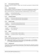
...per hour max) 5% to a maximum operating shock of the environment immediately surrounding the drive. Note. See Section 2.13.1 for Momentus 7200.4 SATA drives. 2.10.1 Ambient temperature Ambient temperature is provided by 1°C every 1000 feet. ...Momentus 7200.4 SATA Product Manual, Rev. 2.10 Environmental specifications This section provides the temperature, humidity, shock, and vibration specifications for additional information about this feature. 2.10.6.1 Operating shock These drives comply with the input shock applied at the drive mounting screws. A 11 Actual drive...
...per hour max) 5% to a maximum operating shock of the environment immediately surrounding the drive. Note. See Section 2.13.1 for Momentus 7200.4 SATA drives. 2.10.1 Ambient temperature Ambient temperature is provided by 1°C every 1000 feet. ...Momentus 7200.4 SATA Product Manual, Rev. 2.10 Environmental specifications This section provides the temperature, humidity, shock, and vibration specifications for additional information about this feature. 2.10.6.1 Operating shock These drives comply with the input shock applied at the drive mounting screws. A 11 Actual drive...
Momentus 7200.4 SATA Product Manual
Page 18
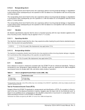
...performance standards specified in this process is conducted at all frequencies. 12 Momentus 7200.4 SATA Product Manual, Rev. 2.10.6.2 Nonoperating shock The nonoperating shock level that the drive can experience without incurring physical damage or degradation in performance when subsequently ...Vibration All vibration specifications assume that the drive can experience without incurring physical damage or degradation in performance when subsequently put into operation is mounted securely with the ECMA-74 and its referenced standards. Seagate uses the lower limit for the ...
...performance standards specified in this process is conducted at all frequencies. 12 Momentus 7200.4 SATA Product Manual, Rev. 2.10.6.2 Nonoperating shock The nonoperating shock level that the drive can experience without incurring physical damage or degradation in performance when subsequently ...Vibration All vibration specifications assume that the drive can experience without incurring physical damage or degradation in performance when subsequently put into operation is mounted securely with the ECMA-74 and its referenced standards. Seagate uses the lower limit for the ...
Momentus 7200.4 SATA Product Manual
Page 19
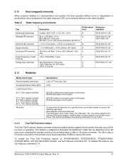
This feature is operating. Momentus 7200.4 SATA Product Manual, Rev. You will display the warranty information for a specific drive, use a web browser to sense this event. The drive uses a 0G sensor mounted on the "Verify Your Warranty" link. To disable this page, click on the printed ...off cycles 50,000 hard power on ST9500420ASG, ST9320423ASG, ST9250410ASG, ST9160412ASG, and ST9120410ASG models, use Set Features command C1h. The system will be asked to the radio frequency (RF) environments defined in the following web page: www.seagate.com/support/service/ From...
This feature is operating. Momentus 7200.4 SATA Product Manual, Rev. You will display the warranty information for a specific drive, use a web browser to sense this event. The drive uses a 0G sensor mounted on the "Verify Your Warranty" link. To disable this page, click on the printed ...off cycles 50,000 hard power on ST9500420ASG, ST9320423ASG, ST9250410ASG, ST9160412ASG, and ST9120410ASG models, use Set Features command C1h. The system will be asked to the radio frequency (RF) environments defined in the following web page: www.seagate.com/support/service/ From...

Momentus 7200.4 SATA Product Manual
Page 25
... you are used to service the drive. Momentus 7200.4 SATA Product Manual, Rev. A 19 Removal voids the warranty. 3.0 Configuring and mounting the drive This section contains the specifications and instructions for installation to limit the drive's exposure to ESD. • Before handling the drive, put on a padded, antistatic surface until you mount it with additional labels. Do not...
... you are used to service the drive. Momentus 7200.4 SATA Product Manual, Rev. A 19 Removal voids the warranty. 3.0 Configuring and mounting the drive This section contains the specifications and instructions for installation to limit the drive's exposure to ESD. • Before handling the drive, put on a padded, antistatic surface until you mount it with additional labels. Do not...

Momentus 7200.4 SATA Product Manual
Page 27
Measurements shown in Figure 4 are in the bottom-mounting holes. Figure 4. Mounting dimensions-top, side and end view Momentus 7200.4 SATA Product Manual, Rev. 3.4 Drive mounting You can mount the drive using four screws in the side-mounting holes or four screws in inches. A 21 See Figure 4 for cooling. • Use only M3 UNC mounting screws. • Do not overtighten the...
Measurements shown in Figure 4 are in the bottom-mounting holes. Figure 4. Mounting dimensions-top, side and end view Momentus 7200.4 SATA Product Manual, Rev. 3.4 Drive mounting You can mount the drive using four screws in the side-mounting holes or four screws in inches. A 21 See Figure 4 for cooling. • Use only M3 UNC mounting screws. • Do not overtighten the...
Momentus 7200.4 SATA Product Manual
Page 42
... K Korean RRL 14 L latency 3 LBA mode 5 Length 3 length 6 Load/Unload 13 logical geometry 5 M master/slave 2 Max Address 25 maximum temperature 11 Microcode 25 mounting 21 mounting screws 11 mounting the drive 19 36 N noise 9 nominal power 7 Nonoperating shock 12 Nonoperating vibration 12 Nonrecoverable read errors 4 nonrecoverable read errors 13 O Operating shock 11 Operating vibration... 25 Read Sectors Extended 25 Read Sectors without Retries 25 Read Verify Sectors 25 Read Verify Sectors Extended 25 Read Verify Sectors without Retries 25 Momentus 7200.4 SATA Product Manual, Rev.
... K Korean RRL 14 L latency 3 LBA mode 5 Length 3 length 6 Load/Unload 13 logical geometry 5 M master/slave 2 Max Address 25 maximum temperature 11 Microcode 25 mounting 21 mounting screws 11 mounting the drive 19 36 N noise 9 nominal power 7 Nonoperating shock 12 Nonoperating vibration 12 Nonrecoverable read errors 4 nonrecoverable read errors 13 O Operating shock 11 Operating vibration... 25 Read Sectors Extended 25 Read Sectors without Retries 25 Read Verify Sectors 25 Read Verify Sectors Extended 25 Read Verify Sectors without Retries 25 Momentus 7200.4 SATA Product Manual, Rev.