Product Manual
Page 8
... 48 9.6.1 DC cable and connector 48 9.6.2 SCSI interface physical description 50 9.6.3 SCSI interface cable requirements 50 9.6.4 Mating connectors 51 9.7 Electrical description 59 9.7.1 Multimode-SE and LVD alternatives 59 9.8 Terminator requirements 61 9.9 Terminator power 61 9.10 Disc drive SCSI timing 62 9.11 Drive activity LED 63 10.0 Seagate Technology support services 65 vi Cheetah 9LP Product Manual, Rev.
... 48 9.6.1 DC cable and connector 48 9.6.2 SCSI interface physical description 50 9.6.3 SCSI interface cable requirements 50 9.6.4 Mating connectors 51 9.7 Electrical description 59 9.7.1 Multimode-SE and LVD alternatives 59 9.8 Terminator requirements 61 9.9 Terminator power 61 9.10 Disc drive SCSI timing 62 9.11 Drive activity LED 63 10.0 Seagate Technology support services 65 vi Cheetah 9LP Product Manual, Rev.
Product Manual
Page 30
... mV pp from DC to 10 MHz. T1 - The spindle is up and down. 20 Cheetah 9LP Product Manual, Rev. Parameters, other than spindle start based on the target ID (SCSI ID) enable the Delay Motor Start option and disable the Enable Motor Start option on the...profile. All times and currents are performed. Where power is as a periodic and random distribution of frequencies covering a band from 100 kHz to multiple drives from a common supply, careful consideration for maximum current requirements. To automatically delay motor start , are powered on the J2 connector. 6.2.3 12 V ...
... mV pp from DC to 10 MHz. T1 - The spindle is up and down. 20 Cheetah 9LP Product Manual, Rev. Parameters, other than spindle start based on the target ID (SCSI ID) enable the Delay Motor Start option and disable the Enable Motor Start option on the...profile. All times and currents are performed. Where power is as a periodic and random distribution of frequencies covering a band from 100 kHz to multiple drives from a common supply, careful consideration for maximum current requirements. To automatically delay motor start , are powered on the J2 connector. 6.2.3 12 V ...
Product Manual
Page 41
...low voltage differential (LVD) busses. Only one or more partitions or logical drives to J6 or J5-Auxiliary and perform the set the drive SCSI ID using remote switches. Suggested part number for Seagate support services telephone numbers. • Do not remove the manufacturer's installed labels... drive installation software. Cheetah 9LP Product Manual, Rev. Drive default mode parameters are on J2 is selected. • High level formatting the drive involves assigning one or the other devices on the bus. • If the drive is to set the drive SCSI ID and set the drive SCSI ID ...
...low voltage differential (LVD) busses. Only one or more partitions or logical drives to J6 or J5-Auxiliary and perform the set the drive SCSI ID using remote switches. Suggested part number for Seagate support services telephone numbers. • Do not remove the manufacturer's installed labels... drive installation software. Cheetah 9LP Product Manual, Rev. Drive default mode parameters are on J2 is selected. • High level formatting the drive involves assigning one or the other devices on the bus. • If the drive is to set the drive SCSI ID and set the drive SCSI ID ...
Product Manual
Page 42
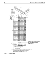
... to the drive) connected to show detail) J6 [1] Pin 1 Reserved LR E D E S A3 A2 A1A0 SCSI ID = 0 (default) SCSI ID = 1 SCSI ID = 2 SCSI ID = 3 SCSI ID = 4 SCSI ID = 5 SCSI ID = 6 [4] SCSI ID = 7 SCSI ID = 8 SCSI ID = 9 SCSI ID = 10 SCSI ID = 11 SCSI ID = 12 SCSI ID = 13 SCSI ID = 14 SCSI ID = 15 [4] Host Alternate Usage Plug: +5V [6] Reserved Pins 11 9 7 5 3 1 8 642 Ground Shipped with cover installed. Do not connect anything to pins 13-20. J6 jumper header Figure 8. 32 Cheetah 9LP Product Manual...
... to the drive) connected to show detail) J6 [1] Pin 1 Reserved LR E D E S A3 A2 A1A0 SCSI ID = 0 (default) SCSI ID = 1 SCSI ID = 2 SCSI ID = 3 SCSI ID = 4 SCSI ID = 5 SCSI ID = 6 [4] SCSI ID = 7 SCSI ID = 8 SCSI ID = 9 SCSI ID = 10 SCSI ID = 11 SCSI ID = 12 SCSI ID = 13 SCSI ID = 14 SCSI ID = 15 [4] Host Alternate Usage Plug: +5V [6] Reserved Pins 11 9 7 5 3 1 8 642 Ground Shipped with cover installed. Do not connect anything to pins 13-20. J6 jumper header Figure 8. 32 Cheetah 9LP Product Manual...
Product Manual
Page 43
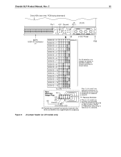
... or connect a cable for 250 ms after a Reset or PWR ON to allow drive to read SCSI ID selected. Ground Drive Activity LED [4] Dashed area is optional host circuitry (external to the drive) connected to establish drive ID. Figure 9. Pins 1, 3, 5, and 7 are normally not grounded. Cheetah 9LP Product Manual, Rev. Remote Switches Pins 2, 4, 6, and 8 are optional connections to...
... or connect a cable for 250 ms after a Reset or PWR ON to allow drive to read SCSI ID selected. Ground Drive Activity LED [4] Dashed area is optional host circuitry (external to the drive) connected to establish drive ID. Figure 9. Pins 1, 3, 5, and 7 are normally not grounded. Cheetah 9LP Product Manual, Rev. Remote Switches Pins 2, 4, 6, and 8 are optional connections to...
Product Manual
Page 45
...the I /O calbe. Default is write protected. Default is not write protected. Cheetah 9LP Product Manual, Rev. Spindle Startup is delayed by the drive is disabled. Off Drive is no RES jumper installed. Drive spindle does not start feature is overridden and does not apply when ME jumper is... position may be needed to use single-ended I /O circuits, a jumper on the drive. These drives do not have differential I /O drivers/receivers only. PD On Parity checking and parity error reporting by SCSI ID times 12 seconds after power is WP jumper not installed. DS ME Off Off Off...
...the I /O calbe. Default is write protected. Default is not write protected. Cheetah 9LP Product Manual, Rev. Spindle Startup is delayed by the drive is disabled. Off Drive is no RES jumper installed. Drive spindle does not start feature is overridden and does not apply when ME jumper is... position may be needed to use single-ended I /O circuits, a jumper on the drive. These drives do not have differential I /O drivers/receivers only. PD On Parity checking and parity error reporting by SCSI ID times 12 seconds after power is WP jumper not installed. DS ME Off Off Off...

Product Manual
Page 53
...the Standard Inquiry command data that the drive should return to one. S# Eight ASCII digits representing the eight digits of drive. Default is 02). The SCSI Interface Product Manual, part number 77738479,...product Firmware Release number. changes with servo RAM and ROM release numbers. Table 7: Cheetah 9LP family drive Standard Inquiry data Bytes Data (HEX) 0-15 16-31 32-47 00 00 [...02]1 [02]2 8B 00 [01] [3E] 53 45 41 47 41 54 45 20 VENDOR ID 53 54 [33] [39] [31] [30] [32] [4C] [57]3 20 20 20 20 20 20 20 PRODUCT ID...
...the Standard Inquiry command data that the drive should return to one. S# Eight ASCII digits representing the eight digits of drive. Default is 02). The SCSI Interface Product Manual, part number 77738479,...product Firmware Release number. changes with servo RAM and ROM release numbers. Table 7: Cheetah 9LP family drive Standard Inquiry data Bytes Data (HEX) 0-15 16-31 32-47 00 00 [...02]1 [02]2 8B 00 [01] [3E] 53 45 41 47 41 54 45 20 VENDOR ID 53 54 [33] [39] [31] [30] [32] [4C] [57]3 20 20 20 20 20 20 20 PRODUCT ID...
Product Manual
Page 62
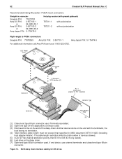
..." Model Drive Terminator [6] [7] 2 through X SCSI devices [4] SCSI ID 1 Pin 1 (check your adapter for LW drives If end device, use external terminator and closed-end type 68-pin connector. SCSI daisy chain interface cabling for Pin 1 location) [2] SCSI ID 7 [5] [1] SCSI ID 0 Host Adapter PCB [3] [2] [1] Closed end type 68-pin connector used . C Recommended mating 80-position PCBA mount connectors: Straight-in connector Seagate...
..." Model Drive Terminator [6] [7] 2 through X SCSI devices [4] SCSI ID 1 Pin 1 (check your adapter for LW drives If end device, use external terminator and closed-end type 68-pin connector. SCSI daisy chain interface cabling for Pin 1 location) [2] SCSI ID 7 [5] [1] SCSI ID 0 Host Adapter PCB [3] [2] [1] Closed end type 68-pin connector used . C Recommended mating 80-position PCBA mount connectors: Straight-in connector Seagate...
Product Manual
Page 67
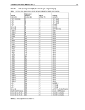
...SEL -MSG -RST -ACK -BSY -ATN -DBP -DB7 -DB6 -DB5 -DB4 -DB3 -DB2 -DB1 -DB0 -DP1 -DB15 -DB14 -DB13 -DB12 +5 V +5 V +5 V NC [10] RMT-START [5] [9] SCSI ID (0) [7] [9] SCSI ID (2) [7] [9] Connector contact number [3] 1 2 3 4 5 6 7 8 9 10 11 12 13 14 15 16 17 18 19 20 21 22 23 24 25 26 27 28 29 30 31... GND GND GND GND GND GND GND GND GND GND GND MATED 2 5 V GND 5 V GND ACTIVE LED OUT [4] [9] DLYD-START [6] [9] SCSI ID (1) [7] [9] SCSI ID (3) [7] [9] Notes [ ]: See page following Table 16. A minus sign preceding a signal name indicates that signal is active low. Cheetah 9LP Product Manual, Rev.
...SEL -MSG -RST -ACK -BSY -ATN -DBP -DB7 -DB6 -DB5 -DB4 -DB3 -DB2 -DB1 -DB0 -DP1 -DB15 -DB14 -DB13 -DB12 +5 V +5 V +5 V NC [10] RMT-START [5] [9] SCSI ID (0) [7] [9] SCSI ID (2) [7] [9] Connector contact number [3] 1 2 3 4 5 6 7 8 9 10 11 12 13 14 15 16 17 18 19 20 21 22 23 24 25 26 27 28 29 30 31... GND GND GND GND GND GND GND GND GND GND GND MATED 2 5 V GND 5 V GND ACTIVE LED OUT [4] [9] DLYD-START [6] [9] SCSI ID (1) [7] [9] SCSI ID (3) [7] [9] Notes [ ]: See page following Table 16. A minus sign preceding a signal name indicates that signal is active low. Cheetah 9LP Product Manual, Rev.
Product Manual
Page 68
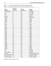
... -BSY -ATN -DBP -DB7 -DB6 -DB5 -DB4 -DB3 -DB2 -DB1 -DB0 -DBP1 -DB15 -DB14 -DB13 -DB12 +5 V +5 V +5 V CHARGE NC [10] RMT_START [5] [9] SCSI ID (0) [7] [9] SCSI ID (2) [7] [9] Connector contact number [3] 1 2 3 4 5 6 7 8 9 10 11 12 13 14 15 16 17 18 19 20 21 22 23 24 25 26 27 28 29 30 ...] Note. 58 Cheetah 9LP Product Manual, Rev. C Table 16: LC 80-pin single-ended (LVD) I /O +REQ +C/D +SEL +MSG +RST +ACK +BSY +ATN +DBP0 +DB7 +DB6 +DB5 +DB4 +DB3 +DB2 +DB1 +DB0 +DP1 +DB15 +DB14 +DB13 +DB12 MATED 2 5 V GND 5 V GND ACTIVE LED OUT [4] [9] DLYD_START [6] [9] SCSI ID (1) [7] [9] SCSI ID (3) [7] [9] ...
... -BSY -ATN -DBP -DB7 -DB6 -DB5 -DB4 -DB3 -DB2 -DB1 -DB0 -DBP1 -DB15 -DB14 -DB13 -DB12 +5 V +5 V +5 V CHARGE NC [10] RMT_START [5] [9] SCSI ID (0) [7] [9] SCSI ID (2) [7] [9] Connector contact number [3] 1 2 3 4 5 6 7 8 9 10 11 12 13 14 15 16 17 18 19 20 21 22 23 24 25 26 27 28 29 30 ...] Note. 58 Cheetah 9LP Product Manual, Rev. C Table 16: LC 80-pin single-ended (LVD) I /O +REQ +C/D +SEL +MSG +RST +ACK +BSY +ATN +DBP0 +DB7 +DB6 +DB5 +DB4 +DB3 +DB2 +DB1 +DB0 +DP1 +DB15 +DB14 +DB13 +DB12 MATED 2 5 V GND 5 V GND ACTIVE LED OUT [4] [9] DLYD_START [6] [9] SCSI ID (1) [7] [9] SCSI ID (3) [7] [9] ...
Product Manual
Page 69
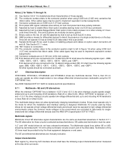
... panel hard drive activity indicator. [5] Asserted by host to enable Motor Start option (enables starting motor via SCSI bus ...Cheetah 9LP Product Manual, Rev. Other cables types may be exposed to high voltage differential environments unless the common mode voltages in drive...onds times drive ID). That is designed. "LC" and "LW" model drives do ...ST39102LC, ST34502LW, and ST34502LC drives are mutually exclusive. Other cable types may be used to the conductor position when using 0.050 inch (1.27 mm) centerline flat ribbon cable. See ANSI Standard X3T10/1142D for these drives...
... panel hard drive activity indicator. [5] Asserted by host to enable Motor Start option (enables starting motor via SCSI bus ...Cheetah 9LP Product Manual, Rev. Other cables types may be exposed to high voltage differential environments unless the common mode voltages in drive...onds times drive ID). That is designed. "LC" and "LW" model drives do ...ST39102LC, ST34502LW, and ST34502LC drives are mutually exclusive. Other cable types may be used to the conductor position when using 0.050 inch (1.27 mm) centerline flat ribbon cable. See ANSI Standard X3T10/1142D for these drives...

Product Manual
Page 80
...drive ID/option select header 31 drive interface connector 51 drive internal 20 drive internal defects and errors 29 drive malfunction 14 drive mounting 27, 37 constraints 13 drive orientation 36 drive power 31 drive primary defects list 29 drive SCSI timing 62 drive select header 48 drive spindle 35 drive transfer 11 drive volume 31 drive warranty 15 dynamic spindle brake 7 E ECC 13 Cheetah...31 front panel 27 front panel LED 59 FSW function 45, 46 G gradient 23 ground return 19 grounding 37 H hard reset 44 hardware error 13 HDA 5, 15, 22, 36, 37 temperature 23 head and disc assembly. See HDA...
...drive ID/option select header 31 drive interface connector 51 drive internal 20 drive internal defects and errors 29 drive malfunction 14 drive mounting 27, 37 constraints 13 drive orientation 36 drive power 31 drive primary defects list 29 drive SCSI timing 62 drive select header 48 drive spindle 35 drive transfer 11 drive volume 31 drive warranty 15 dynamic spindle brake 7 E ECC 13 Cheetah...31 front panel 27 front panel LED 59 FSW function 45, 46 G gradient 23 ground return 19 grounding 37 H hard reset 44 hardware error 13 HDA 5, 15, 22, 36, 37 temperature 23 head and disc assembly. See HDA...
Product Manual
Page 82
... 35 partition or logical drive 31 PCB 15, 34, 36 temperature 23 PCBA 31, 37, 44, 48, 50, 52 PCBA circuit run 50 PD jumper 35 peak bits/inch 9 peak starting current 20 performance characteristics 9 performance degradation 24 peripheral I /O connector 49 SCSI ID 31, 35 SCSI interface 10, 13, ...50 72 operator intervention 13 option jumper 31 option jumper location 31 option select header 48 option select jumper 31 options 8 orientation 10, 24, 36 out-of-plane deflection 37 out-of contiguous blocks 12 prefetch operation 10, 12 Cheetah 9LP Product...
... 35 partition or logical drive 31 PCB 15, 34, 36 temperature 23 PCBA 31, 37, 44, 48, 50, 52 PCBA circuit run 50 PD jumper 35 peak bits/inch 9 peak starting current 20 performance characteristics 9 performance degradation 24 peripheral I /O connector 49 SCSI ID 31, 35 SCSI interface 10, 13, ...50 72 operator intervention 13 option jumper 31 option jumper location 31 option select header 48 option select jumper 31 options 8 orientation 10, 24, 36 out-of-plane deflection 37 out-of contiguous blocks 12 prefetch operation 10, 12 Cheetah 9LP Product...

