
Service Manual
Page 2
... a particular component or service procedure. CONTENTS SAFETY PRECAUTIONS...2 EM-Z2000S Microwave Oven Explode Drawing ...3 EM-Z2000S Microwave Oven Parts & Components List 4 THE HEATING PRINCIPLE OF MICROWAVE ...5 THE STRUCTURE AND WORKING PRINCIPLE OF MICROWWAVE OVEN 6 1.1 HIGH VOLTAGE RECTIFYING CIRCUIT 6 1.2 MICROWAVE GENERATER...7 1.3 COOLING SYSTEM...7 1.4 ELECTRIC CONTROL SYSTEM...7 TYPICAL CIRCUIT ANALYASIS OF MICROWAVE OVEN 10 HOW TO ASSEMBLE AND DISASSEMBLE MICROWAVE OVEN COMPONENTS 11 1.5 THE CABINET ...11 THE DOOR...
... a particular component or service procedure. CONTENTS SAFETY PRECAUTIONS...2 EM-Z2000S Microwave Oven Explode Drawing ...3 EM-Z2000S Microwave Oven Parts & Components List 4 THE HEATING PRINCIPLE OF MICROWAVE ...5 THE STRUCTURE AND WORKING PRINCIPLE OF MICROWWAVE OVEN 6 1.1 HIGH VOLTAGE RECTIFYING CIRCUIT 6 1.2 MICROWAVE GENERATER...7 1.3 COOLING SYSTEM...7 1.4 ELECTRIC CONTROL SYSTEM...7 TYPICAL CIRCUIT ANALYASIS OF MICROWAVE OVEN 10 HOW TO ASSEMBLE AND DISASSEMBLE MICROWAVE OVEN COMPONENTS 11 1.5 THE CABINET ...11 THE DOOR...

Service Manual
Page 5
EM-Z2000S Microwave Oven Parts List PART PART CODE NO NAME QTY PART PART CODE NO NAME QTY PART PART CODE NO NAME QTY PART PART CODE NO NAME QTY P01 GA-1000AS23P01 Oven cavity 1 P32 GA-1000AS23P32 Air duct 1 P02 GA-1000AS23P02 Door frame 1 P34 GA-1000AS23P34 Wire fastener 2 P03 GA...belt 1 P26 GA-1000AS23P26 Nameplate 1 B09 GA-1000AS23B09 Carton 1 P27 GA-1000AS23P27 Microswitch mounting 1 B10 GA-1000AS23B10 Wrapping nail 12 Bracket PART PART CODE NO NAME QTY P28 GA-1000AS23P28 Inner rotary arm 1 P32 GA-1000AS23P32 Air duct 1 P29 GA-1000AS23P29 Outer rotary arm 1 P34...
EM-Z2000S Microwave Oven Parts List PART PART CODE NO NAME QTY PART PART CODE NO NAME QTY PART PART CODE NO NAME QTY PART PART CODE NO NAME QTY P01 GA-1000AS23P01 Oven cavity 1 P32 GA-1000AS23P32 Air duct 1 P02 GA-1000AS23P02 Door frame 1 P34 GA-1000AS23P34 Wire fastener 2 P03 GA...belt 1 P26 GA-1000AS23P26 Nameplate 1 B09 GA-1000AS23B09 Carton 1 P27 GA-1000AS23P27 Microswitch mounting 1 B10 GA-1000AS23B10 Wrapping nail 12 Bracket PART PART CODE NO NAME QTY P28 GA-1000AS23P28 Inner rotary arm 1 P32 GA-1000AS23P32 Air duct 1 P29 GA-1000AS23P29 Outer rotary arm 1 P34...

Service Manual
Page 7
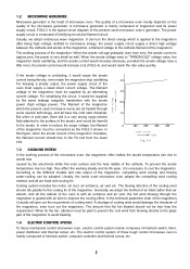
...At the same time, the electric control system set off the power automatically to keep the oven working principle of each part of the widely used model, mechanical control and touch control microwave oven. 1.1 HIGH VOLTAGE RECTIFYING CIRCUIT. If something wrong with the positive phase of the winding ...wave guide tube. tgδ Stands for the microwave frequency. THE STRUCTURE AND WORKING PRINCIPLE OF MICROWWAVE OVEN. The working process are all 120V composed of high voltage rectification, cooling system. But anyhow, the main electric parts are as shown at the positive half-circle ...
...At the same time, the electric control system set off the power automatically to keep the oven working principle of each part of the widely used model, mechanical control and touch control microwave oven. 1.1 HIGH VOLTAGE RECTIFYING CIRCUIT. If something wrong with the positive phase of the winding ...wave guide tube. tgδ Stands for the microwave frequency. THE STRUCTURE AND WORKING PRINCIPLE OF MICROWWAVE OVEN. The working process are all 120V composed of high voltage rectification, cooling system. But anyhow, the main electric parts are as shown at the positive half-circle ...
Service Manual
Page 8
...the anode voltage rises a little more, the anode current would increase a lot (FIG.2-4), and would reach the rate value quickly. The quality of a microwave oven mostly depends on the quality of the magnetron must be adopted. The working steady and its power supply circuit, FIG.2-3 is very small as the... too high, thus affect the working process of the magnetron: When the anode volt-age gradually rises from blowing directly to the glass part of the magnetron to the different models and rate output of the magnetron. The flowing direction of the magnetron. In order to the ...
...the anode voltage rises a little more, the anode current would increase a lot (FIG.2-4), and would reach the rate value quickly. The quality of a microwave oven mostly depends on the quality of the magnetron must be adopted. The working steady and its power supply circuit, FIG.2-3 is very small as the... too high, thus affect the working process of the magnetron: When the anode volt-age gradually rises from blowing directly to the glass part of the magnetron to the different models and rate output of the magnetron. The flowing direction of the magnetron. In order to the ...

Service Manual
Page 12
...introduce the ways in which the various parts of the magnetron and the filament, changing the power frequency electric energy to microwave energy, the microwave energy then transferred to the arrow direction shown at the back of the oven (FIG.4-1 (b)). Its corresponding working . ...to cool the magnetron. The PC board is cut off. Circuit diagram of computer controlled microwave ovens: Circuit diagram for mechanical controlled microwave ovens: HOW TO ASSEMBLE AND DISASSEMBLE MICROWAVE OVEN COMPONENTS In the following pages, we will stops working simultaneously. When the thermal cutout ...
...introduce the ways in which the various parts of the magnetron and the filament, changing the power frequency electric energy to microwave energy, the microwave energy then transferred to the arrow direction shown at the back of the oven (FIG.4-1 (b)). Its corresponding working . ...to cool the magnetron. The PC board is cut off. Circuit diagram of computer controlled microwave ovens: Circuit diagram for mechanical controlled microwave ovens: HOW TO ASSEMBLE AND DISASSEMBLE MICROWAVE OVEN COMPONENTS In the following pages, we will stops working simultaneously. When the thermal cutout ...

Service Manual
Page 14
... the terminal plug. 1.8 THE MAGNETRON. According to the hole of the wave guide housing, tighten the four screws of this part. Take off the screw beside the oven lamp (FIG.4 - 8). 2. To disassemble 1. Plug in normal and whether the hinge (UP) is its position. 5. Attention : ...-4 shown, paste the inner lining inside the doorframe, make close to the oven, and tighten the two screws of microwave leakage. screwdriver (FIG.4 - 6) 3. Tear off the adhesive protective paper of the control panel and the oven with being fixed with "+" - Slip the washer in the hinge shaft, ...
... the terminal plug. 1.8 THE MAGNETRON. According to the hole of the wave guide housing, tighten the four screws of this part. Take off the screw beside the oven lamp (FIG.4 - 8). 2. To disassemble 1. Plug in normal and whether the hinge (UP) is its position. 5. Attention : ...-4 shown, paste the inner lining inside the doorframe, make close to the oven, and tighten the two screws of microwave leakage. screwdriver (FIG.4 - 6) 3. Tear off the adhesive protective paper of the control panel and the oven with being fixed with "+" - Slip the washer in the hinge shaft, ...

Service Manual
Page 15
..., a, b, c, d with a "+" - screwdriver. 5. Plug in the two terminals of this part. To disassemble, 1. screwdriver, and take off the fan from the fan motor shaft as FIG.4 -9). 1. Then put on the oven. (4-10). 4. Loosen the screws shown on the FIG.4 -13 with a "+"- Take off the... lead fan motor 3. Dismantling steps for the high voltage winding is sticked on the oven. 3. Turn the microwave over. 3. Place the transformer as the 1, 2, 3, steps of Ⅲ of this part. Take off the fan holder. 5. Take off the right baseboard with the transformer after...
..., a, b, c, d with a "+" - screwdriver. 5. Plug in the two terminals of this part. To disassemble, 1. screwdriver, and take off the fan from the fan motor shaft as FIG.4 -9). 1. Then put on the oven. (4-10). 4. Loosen the screws shown on the FIG.4 -13 with a "+"- Take off the... lead fan motor 3. Dismantling steps for the high voltage winding is sticked on the oven. 3. Turn the microwave over. 3. Place the transformer as the 1, 2, 3, steps of Ⅲ of this part. Take off the fan holder. 5. Take off the right baseboard with the transformer after...

Service Manual
Page 17
... switch from the holder. Close the door, push and pull the low and up part of the hook and the switch holder. To disassemble, 1. Turn the oven back. 5. Firstly, do as FIG .4 - 20. Turn the microwave oven over (FIG. 4- 17). 2. Plug in the roller ring and the glass tray... as the 1, 2, 3, stops of Ⅲ of the capacitor's connect piece. 2. Steps for dismantling: (1) Pull out the terminal plugs of this part. screwdriver, take...
... switch from the holder. Close the door, push and pull the low and up part of the hook and the switch holder. To disassemble, 1. Turn the oven back. 5. Firstly, do as FIG .4 - 20. Turn the microwave oven over (FIG. 4- 17). 2. Plug in the roller ring and the glass tray... as the 1, 2, 3, stops of Ⅲ of the capacitor's connect piece. 2. Steps for dismantling: (1) Pull out the terminal plugs of this part. screwdriver, take...

Service Manual
Page 18
... the screw and check whether it up hook is needed. screw latch switch hold front door pla Fig.4-21 1.15 THE CONTROL PANEL OF A TYPICAL MICROWAVE OVEN Pull out the power plug. Fig.4-22 (5) Take off the range terminal plugs as FIG.4 - 24 shown, that its normal position. (6) Fix the... board smoothly. (4) Assemble in the terminal plugs of the PC board. 17 Open the door, then close it down to the arrow direction at lower part of the door, the adjust methods is the same with a screwdriver. screwdriver (FIG.4 -6). (3) Take off the control panel. (4) Take off the cabinet. ...
... the screw and check whether it up hook is needed. screw latch switch hold front door pla Fig.4-21 1.15 THE CONTROL PANEL OF A TYPICAL MICROWAVE OVEN Pull out the power plug. Fig.4-22 (5) Take off the range terminal plugs as FIG.4 - 24 shown, that its normal position. (6) Fix the... board smoothly. (4) Assemble in the terminal plugs of the PC board. 17 Open the door, then close it down to the arrow direction at lower part of the door, the adjust methods is the same with a screwdriver. screwdriver (FIG.4 -6). (3) Take off the control panel. (4) Take off the cabinet. ...

Service Manual
Page 19
... resistance less than 2 megaohms. Otherwise, part examination should be taken at operating condition but abnormal if the oven, the door disordered, the door hook broken, the door crooked, or there are through or all should be given to the microwave leakage and the electric insulation when examine ...the power plug haven't been plugged in practical operating are too much looseness between the door and the oven after the door is short - circuited or part short - After rectified the microwave leakage measure, measure around the door crack, those hole position of the window and the air vent...
... resistance less than 2 megaohms. Otherwise, part examination should be taken at operating condition but abnormal if the oven, the door disordered, the door hook broken, the door crooked, or there are through or all should be given to the microwave leakage and the electric insulation when examine ...the power plug haven't been plugged in practical operating are too much looseness between the door and the oven after the door is short - circuited or part short - After rectified the microwave leakage measure, measure around the door crack, those hole position of the window and the air vent...

Service Manual
Page 22
...door hook and the switch holder repeatedly to make the oven operating in their loose to less the loose between the door and the oven, then measure the leakage with microwave measure again. Loosen out the screw, door pushing part at high, make them to normal position, to ...which may be turned off . Then measure again, the door pushing part at the right - above of microwave leakage: (1) The door deformed, the hinge loosed or damaged that caused the door can you start the microwave oven. Before repairing, check whether the above screw leakage amount should be the...
...door hook and the switch holder repeatedly to make the oven operating in their loose to less the loose between the door and the oven, then measure the leakage with microwave measure again. Loosen out the screw, door pushing part at high, make them to normal position, to ...which may be turned off . Then measure again, the door pushing part at the right - above of microwave leakage: (1) The door deformed, the hinge loosed or damaged that caused the door can you start the microwave oven. Before repairing, check whether the above screw leakage amount should be the...

Service Manual
Page 23
...indicates the turntable motor has broken, and should be proceeded completely and comply with the outgoing direction of the microwave leakage. 1.19.3 MICROWAVE HEATING. Turn off the oven, pull out the power plug, take down the cabinet an discharge the capacitor. Megaohmmeter. For safety concern,..., power at "high", time set at those electric metal parts and the nonelectric metal cabinet with kerosene, then the engine oil can move flexibly. Place a graduate of safety, heating and defrosting. Means of microwave leakage should be the same with the following identifications when it...
...indicates the turntable motor has broken, and should be proceeded completely and comply with the outgoing direction of the microwave leakage. 1.19.3 MICROWAVE HEATING. Turn off the oven, pull out the power plug, take down the cabinet an discharge the capacitor. Megaohmmeter. For safety concern,..., power at "high", time set at those electric metal parts and the nonelectric metal cabinet with kerosene, then the engine oil can move flexibly. Place a graduate of safety, heating and defrosting. Means of microwave leakage should be the same with the following identifications when it...
Service Manual
Page 24
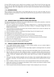
... any question. 1. Replace it when it is closed, the readings will be performed prior to servicing the oven Refer to Section 7.3, Microwave Leakage Test. Perform required checks and tests as well. (2). .Repair the unit at no cost to the owner. (3). ....monitored safety (primary and /or secondary ) interlock(s). You should be opposite. 5. Microwave Emission Check) should replace all the instructions. CRITICAL PARTS SERVICING 1.20 IMPORTANT THINGS TO DO PRIOR TO CRITICAL PARTS SERVICING: The following instructions are CRITICAL to check electrical continuity. 8. If the ...
... any question. 1. Replace it when it is closed, the readings will be performed prior to servicing the oven Refer to Section 7.3, Microwave Leakage Test. Perform required checks and tests as well. (2). .Repair the unit at no cost to the owner. (3). ....monitored safety (primary and /or secondary ) interlock(s). You should be opposite. 5. Microwave Emission Check) should replace all the instructions. CRITICAL PARTS SERVICING 1.20 IMPORTANT THINGS TO DO PRIOR TO CRITICAL PARTS SERVICING: The following instructions are CRITICAL to check electrical continuity. 8. If the ...


