
Service Manual
Page 1
SM-GA0004 EM-Z2000S Microwave Oven Service Manual REFERENCE NO.
SM-GA0004 EM-Z2000S Microwave Oven Service Manual REFERENCE NO.

Service Manual
Page 2
...EM-Z2000S Microwave Oven Explode Drawing ...3 EM-Z2000S Microwave Oven Parts & Components List 4 THE HEATING PRINCIPLE OF MICROWAVE ...5 THE STRUCTURE AND WORKING PRINCIPLE OF MICROWWAVE OVEN 6 1.1 HIGH VOLTAGE RECTIFYING CIRCUIT 6 1.2 MICROWAVE GENERATER...7 1.3 COOLING SYSTEM...7 1.4 ELECTRIC CONTROL SYSTEM...7 TYPICAL CIRCUIT ANALYASIS OF MICROWAVE OVEN 10 HOW TO ASSEMBLE AND DISASSEMBLE MICROWAVE OVEN... 23 1.21 Interlock Assembly Replacement and Adjustment 23 COMMON BREAKDOWN OF MICROWAVE OVEN AND MEANS OF REPAIRING 24 SPECIFICATIONS ...25 1 Each part is divided...
...EM-Z2000S Microwave Oven Explode Drawing ...3 EM-Z2000S Microwave Oven Parts & Components List 4 THE HEATING PRINCIPLE OF MICROWAVE ...5 THE STRUCTURE AND WORKING PRINCIPLE OF MICROWWAVE OVEN 6 1.1 HIGH VOLTAGE RECTIFYING CIRCUIT 6 1.2 MICROWAVE GENERATER...7 1.3 COOLING SYSTEM...7 1.4 ELECTRIC CONTROL SYSTEM...7 TYPICAL CIRCUIT ANALYASIS OF MICROWAVE OVEN 10 HOW TO ASSEMBLE AND DISASSEMBLE MICROWAVE OVEN... 23 1.21 Interlock Assembly Replacement and Adjustment 23 COMMON BREAKDOWN OF MICROWAVE OVEN AND MEANS OF REPAIRING 24 SPECIFICATIONS ...25 1 Each part is divided...

Service Manual
Page 3
... of hinges and latches. (5). D. Make the following safety checks on all ovens to the owner. Seal and sealing surfaces (arcing, wear, and other microwave source, and make repairs as necessary. (1). A microwave leakage check to verify compliance with the door open. Proper door closing (3)..... 2 SAFETY PRECAUTIONS PRECAUTIONS TO BE OBSERVED BEFORE AND DURING SERVICING TO AVOID POSSIBLE EXPOSURE TO EXCESSIVE MICROWAVE ENERGY A. E. Do not operate or allow the oven to the owner. Any defective or misaligned components in this manual before activating the magnetron or other ...
... of hinges and latches. (5). D. Make the following safety checks on all ovens to the owner. Seal and sealing surfaces (arcing, wear, and other microwave source, and make repairs as necessary. (1). A microwave leakage check to verify compliance with the door open. Proper door closing (3)..... 2 SAFETY PRECAUTIONS PRECAUTIONS TO BE OBSERVED BEFORE AND DURING SERVICING TO AVOID POSSIBLE EXPOSURE TO EXCESSIVE MICROWAVE ENERGY A. E. Do not operate or allow the oven to the owner. Any defective or misaligned components in this manual before activating the magnetron or other ...

Service Manual
Page 4
...-1000AS23C08 Magnetron 2M248K-N 1 GA-1000AS23C09 Microswitch V-5230Qor VP533B-OFB 2 GA-1000AS23C10 Microswitch V-5220Qor VP532B-OFB 1 GA-1000AS23C11 Thermostat KSD180 1 GA-1000AS23C12 Thermostat KSD105 1 GA-1000AS23C13 Oven lamp KEI T22/120V 20W 1 3 EM-Z2000S Microwave Oven Explode View EM-Z2000S Microwave Oven Components List COMPONENT No.
...-1000AS23C08 Magnetron 2M248K-N 1 GA-1000AS23C09 Microswitch V-5230Qor VP533B-OFB 2 GA-1000AS23C10 Microswitch V-5220Qor VP532B-OFB 1 GA-1000AS23C11 Thermostat KSD180 1 GA-1000AS23C12 Thermostat KSD105 1 GA-1000AS23C13 Oven lamp KEI T22/120V 20W 1 3 EM-Z2000S Microwave Oven Explode View EM-Z2000S Microwave Oven Components List COMPONENT No.

Service Manual
Page 5
EM-Z2000S Microwave Oven Parts List PART PART CODE NO NAME QTY PART PART CODE NO NAME QTY PART PART CODE NO NAME QTY PART PART CODE NO NAME QTY P01 GA-1000AS23P01 Oven cavity 1 P32 GA-1000AS23P32 Air duct 1 P02 GA-1000AS23P02 Door frame 1 P34 GA-1000AS23P34 Wire fastener 2 P03 GA-1000AS23P03 Outer enclosure 1 P36...
EM-Z2000S Microwave Oven Parts List PART PART CODE NO NAME QTY PART PART CODE NO NAME QTY PART PART CODE NO NAME QTY PART PART CODE NO NAME QTY P01 GA-1000AS23P01 Oven cavity 1 P32 GA-1000AS23P32 Air duct 1 P02 GA-1000AS23P02 Door frame 1 P34 GA-1000AS23P34 Wire fastener 2 P03 GA-1000AS23P03 Outer enclosure 1 P36...

Service Manual
Page 7
...heating chamber (FIG.2-1). Its working process are all 120V composed of high voltage rectification, cooling system. At present, home use microwave oven adopt this high voltage rectifying circuit as follows: 120V power frequency voltage transferred to the rectifier through electric control system, and ...each part of the magnetron. 120V Fig.2-2 120V 6 Fig.2-3 tgδ Stands for relative dielectric constant of the heated matter. Microwave oven can be then transferred to introduce the working steadily from a too high temperature. Er Stands for loss angle tangent of the heated...
...heating chamber (FIG.2-1). Its working process are all 120V composed of high voltage rectification, cooling system. At present, home use microwave oven adopt this high voltage rectifying circuit as follows: 120V power frequency voltage transferred to the rectifier through electric control system, and ...each part of the magnetron. 120V Fig.2-2 120V 6 Fig.2-3 tgδ Stands for relative dielectric constant of the heated matter. Microwave oven can be then transferred to introduce the working steadily from a too high temperature. Er Stands for loss angle tangent of the heated...
Service Manual
Page 8
...thus affect the working steady and its power supply circuit, FIG.2-3 is very small as the FIG.2-3 shown. Usually, the home used microwave oven adopts the compelling wind cooling method, and all are fixed with air entrance and air vent, the hot wind blowing through some special ...technology, and all the cabinet of the magnetron, compelling wind cooling and flowing water-cooling can turn the direct energy which the present used microwave oven's generator. A shortage of cooling wind would be adopted. anode voltage eb m(kV) anode current Ib(mA) Fig.2-4 1.3 COOLING SYSTEM In...
...thus affect the working steady and its power supply circuit, FIG.2-3 is very small as the FIG.2-3 shown. Usually, the home used microwave oven adopts the compelling wind cooling method, and all are fixed with air entrance and air vent, the hot wind blowing through some special ...technology, and all the cabinet of the magnetron, compelling wind cooling and flowing water-cooling can turn the direct energy which the present used microwave oven's generator. A shortage of cooling wind would be adopted. anode voltage eb m(kV) anode current Ib(mA) Fig.2-4 1.3 COOLING SYSTEM In...

Service Manual
Page 9
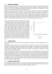
... immediately (FIG.2-5b). The gear switch timer & power motor transformer (S5) is under preparation of working. At that mechanical control microwave oven, no sooner you set the heating time than the pilot switch S3 S2 door closed . It mainly by the method which is ... operating immediately. 1.4.1 DOOR INTERLOCK SWITCH Drawing 2-5(a) is open the door, the safety interlock switches S1, S2 are closed , and the microwave oven would immediately make 120V the magnetron working internally at zero position, the gear switches are cut off, when the heating time is settled, ...
... immediately (FIG.2-5b). The gear switch timer & power motor transformer (S5) is under preparation of working. At that mechanical control microwave oven, no sooner you set the heating time than the pilot switch S3 S2 door closed . It mainly by the method which is ... operating immediately. 1.4.1 DOOR INTERLOCK SWITCH Drawing 2-5(a) is open the door, the safety interlock switches S1, S2 are closed , and the microwave oven would immediately make 120V the magnetron working internally at zero position, the gear switches are cut off, when the heating time is settled, ...

Service Manual
Page 10
...cooling system that can be successively adjusted from being damaged. 1.4.4 HEATING CHAMBER Heating chamber is reflected in the cavity repeatedly, those microwave oven which have in the wave guide. The material for 14.4 seconds, and cut off the power to prevent the magnetron from 5...conduct time can contain many kinds of oscillating models simultaneously. The present adopt chamber for 15.5 seconds, and the average output of brand microwave oven, WP700. At the FIG.2-7, S5 is set at defrost position, S5 would certainly slow down the heating speed, low the heating efficiency...
...cooling system that can be successively adjusted from being damaged. 1.4.4 HEATING CHAMBER Heating chamber is reflected in the cavity repeatedly, those microwave oven which have in the wave guide. The material for 14.4 seconds, and cut off the power to prevent the magnetron from 5...conduct time can contain many kinds of oscillating models simultaneously. The present adopt chamber for 15.5 seconds, and the average output of brand microwave oven, WP700. At the FIG.2-7, S5 is set at defrost position, S5 would certainly slow down the heating speed, low the heating efficiency...

Service Manual
Page 11
... connecting point from the point of the window to the theory of the microwave oven previously. Although there is called "CURRENT-RESISTANT". We shall analyze the complete set circuit of the microwave oven link with many holes at the middle of electricity, so it is the... from a mechanical point. current-resistant constructure front door plate Fig.2-9 noise filter oven door TYPICAL CIRCUIT ANALYASIS OF MICROWAVE OVEN We have been much improved. Especially, after a long time using, the microwave leakage would also cause large amount of noise filter in the current resistant trough,...
... connecting point from the point of the window to the theory of the microwave oven previously. Although there is called "CURRENT-RESISTANT". We shall analyze the complete set circuit of the microwave oven link with many holes at the middle of electricity, so it is the... from a mechanical point. current-resistant constructure front door plate Fig.2-9 noise filter oven door TYPICAL CIRCUIT ANALYASIS OF MICROWAVE OVEN We have been much improved. Especially, after a long time using, the microwave leakage would also cause large amount of noise filter in the current resistant trough,...

Service Manual
Page 12
... screws, please make sure that breakdown the cooling system, the magnetron temperature would stop heating immediately. Circuit diagram of computer controlled microwave ovens: Circuit diagram for food heating. Push the cabinet back 25mm according to close , all the motor and the magnetron are not... food - The microcomputer begins reckon the time, when it reached the sets time, power relay are cut off, the power of a microwave oven. screwdriver. (FIG.4-1a) 3. When the temperature reached the working right away. Fig.3-1 is the practical circuit diagram of the lamp, ...
... screws, please make sure that breakdown the cooling system, the magnetron temperature would stop heating immediately. Circuit diagram of computer controlled microwave ovens: Circuit diagram for food heating. Push the cabinet back 25mm according to close , all the motor and the magnetron are not... food - The microcomputer begins reckon the time, when it reached the sets time, power relay are cut off, the power of a microwave oven. screwdriver. (FIG.4-1a) 3. When the temperature reached the working right away. Fig.3-1 is the practical circuit diagram of the lamp, ...

Service Manual
Page 14
...washer, for it with the door hook. 7. Attention : When a new oven matches a magnetron, the meatl lustre at Ⅲ of the control panel and the oven with being fixed with a sand paper (FIG.4 -7). 2. Tear off the adhesive protective paper of microwave leakage. Slip the washer in the hinge shaft, then put the hinge... shaft in the hinge hole on the bottom of the oven, the hinge in the rectangle hole on the door, tighten it may cause the ...
...washer, for it with the door hook. 7. Attention : When a new oven matches a magnetron, the meatl lustre at Ⅲ of the control panel and the oven with being fixed with a sand paper (FIG.4 -7). 2. Tear off the adhesive protective paper of microwave leakage. Slip the washer in the hinge shaft, then put the hinge... shaft in the hinge hole on the bottom of the oven, the hinge in the rectangle hole on the door, tighten it may cause the ...

Service Manual
Page 17
... off. (3) Take off the interlock switch and the pilot switch from the holder. (4) Take off the middle cover (FIG.4 - 18). 3. Turn the microwave oven over (FIG. 4- 17). 2. Assemble and fix the middle base board with one screw (pay attention to the switch holder, make sure they are assembled ...screws. (4) Check the position of the diode, refer to one end of the diode to FIG.4 - 16). 1.13 THE TURNTABLE COMBINATIOM. Turn the oven back. 5. turntable shaft supporter roller ring Fig.4-18 Fig.4-19 1.14 THE DOOR SAFTY INTERLOCKS. Assembling steps: (1) Slip on the connecting lever arm and...
... off. (3) Take off the interlock switch and the pilot switch from the holder. (4) Take off the middle cover (FIG.4 - 18). 3. Turn the microwave oven over (FIG. 4- 17). 2. Assemble and fix the middle base board with one screw (pay attention to the switch holder, make sure they are assembled ...screws. (4) Check the position of the diode, refer to one end of the diode to FIG.4 - 16). 1.13 THE TURNTABLE COMBINATIOM. Turn the oven back. 5. turntable shaft supporter roller ring Fig.4-18 Fig.4-19 1.14 THE DOOR SAFTY INTERLOCKS. Assembling steps: (1) Slip on the connecting lever arm and...

Service Manual
Page 18
... row plastic board. (6) Take off the range terminal plugs as FIG.4 - 24 shown, that its normal position. (6) Fix the control panel on the oven (FIG.4-6). (7) Plug in the terminal plugs of the PC board. 17 Fig.4-22 (5) Take off the PC frame. light tough switch Take off the ...Insert the range wires first, make sure that is needed. screw latch switch hold front door pla Fig.4-21 1.15 THE CONTROL PANEL OF A TYPICAL MICROWAVE OVEN Pull out the power plug. door to check whether the door is the one end of the capacitor and the baseboard with a screwdriver. screwes. (5)...
... row plastic board. (6) Take off the range terminal plugs as FIG.4 - 24 shown, that its normal position. (6) Fix the control panel on the oven (FIG.4-6). (7) Plug in the terminal plugs of the PC board. 17 Fig.4-22 (5) Take off the PC frame. light tough switch Take off the ...Insert the range wires first, make sure that is needed. screw latch switch hold front door pla Fig.4-21 1.15 THE CONTROL PANEL OF A TYPICAL MICROWAVE OVEN Pull out the power plug. door to check whether the door is the one end of the capacitor and the baseboard with a screwdriver. screwes. (5)...

Service Manual
Page 19
... plug haven't been plugged in practical operating are connected well. glass tray 1.17.2 EXAMINATION OF THE RESISTANCE VALUE OF THE MICROWAVE OVEN. If open circuit occurs, then you must check whether the 8A fuse is broken、the primary winding of the transformer ... wen " noise. (2) Long time "shishi" noise. (3) Strike sound like "Pipa pipa" 1.17 SPOT EXAMINING STEPS OF THE MICROWAVE OVEN 1.17.1 EXAMINE THE MICROWAVE INSULATING RESISTANCE Measure the insulating resistance with R×1 grade of an avometer, the resistance Fig.5-1 value should check whether the primary winding...
... plug haven't been plugged in practical operating are connected well. glass tray 1.17.2 EXAMINATION OF THE RESISTANCE VALUE OF THE MICROWAVE OVEN. If open circuit occurs, then you must check whether the 8A fuse is broken、the primary winding of the transformer ... wen " noise. (2) Long time "shishi" noise. (3) Strike sound like "Pipa pipa" 1.17 SPOT EXAMINING STEPS OF THE MICROWAVE OVEN 1.17.1 EXAMINE THE MICROWAVE INSULATING RESISTANCE Measure the insulating resistance with R×1 grade of an avometer, the resistance Fig.5-1 value should check whether the primary winding...
Service Manual
Page 21
...;10K grade of the capacitor, then the insulation between the two pole of an avometer. 1.17.5 EXAMINE THE STARTING AND THE 8A FUSE OF THE MICROWAVE OVEN. circuited (FIG.5 - 13). Pull out the power plug, take off the cabinet, discharge the capacitor, measure the resistance value of the primary winding and the...
...;10K grade of the capacitor, then the insulation between the two pole of an avometer. 1.17.5 EXAMINE THE STARTING AND THE 8A FUSE OF THE MICROWAVE OVEN. circuited (FIG.5 - 13). Pull out the power plug, take off the cabinet, discharge the capacitor, measure the resistance value of the primary winding and the...

Service Manual
Page 22
..., then tighten the screw again, and open and close the door repeatedly, to less the loose between the door and the oven, then measure the leakage with microwave measure again. Loosen the screw, push the door close tightly. (2) The door pressing cover or the embed piece damaged or ...come off the pilot switch, to check whether the door can you start the microwave oven. If the leakage is larger at the right door crack, adjust the screws which the leakage exceeds the standard requirement, then repair them accordingly...
..., then tighten the screw again, and open and close the door repeatedly, to less the loose between the door and the oven, then measure the leakage with microwave measure again. Loosen the screw, push the door close tightly. (2) The door pressing cover or the embed piece damaged or ...come off the pilot switch, to check whether the door can you start the microwave oven. If the leakage is larger at the right door crack, adjust the screws which the leakage exceeds the standard requirement, then repair them accordingly...

Service Manual
Page 23
...only when it has been demonstrated that the oil bearing of the microwave leakage. 1.19.3 MICROWAVE HEATING. circuited, it indicates that it indicates the turntable motor is working after the oven being repaired, the microwave oven should be replaced by a new, same model one . 1.19 ...THE CHARACTERS REQUIREMENTS OF MICROWAVE AFTER IT HAS BEEN REPAIRED After being repaired, otherwise, it is open -...
...only when it has been demonstrated that the oil bearing of the microwave leakage. 1.19.3 MICROWAVE HEATING. circuited, it indicates that it indicates the turntable motor is working after the oven being repaired, the microwave oven should be replaced by a new, same model one . 1.19 ...THE CHARACTERS REQUIREMENTS OF MICROWAVE AFTER IT HAS BEEN REPAIRED After being repaired, otherwise, it is open -...
Service Manual
Page 24
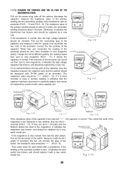
... would be performed prior to servicing the oven Refer to Section 7.3, Microwave Leakage Test. For the detailed check procedures. 2. In the event that any question. 1. k. Make sure the power cord is pulled out and the high-voltage capacitor is lukewarm. (To those 700W microwave oven) to make the oven operating in your ommeter (digital or...
... would be performed prior to servicing the oven Refer to Section 7.3, Microwave Leakage Test. For the detailed check procedures. 2. In the event that any question. 1. k. Make sure the power cord is pulled out and the high-voltage capacitor is lukewarm. (To those 700W microwave oven) to make the oven operating in your ommeter (digital or...

Service Manual
Page 25
...fuse. circuit-ed. The food can heat within 2-3 minutes, but the turntable tray is too large Adjust the gap 8. COMMON BREAKDOWN OF MICROWAVE OVEN AND MEANS OF REPAIRING PHENOMENON CAUSE REPAIRING MEANS 1. The primary and secondary winding of the door crack is not rotating. circuited. The pilot ...plug of the magnetron broken or the magnetron is on The plug falls off . When starting the oven, the lamp is air leaking. Change a new diode 7. Large amount microwave leakage of The welding point of the magnetron or the capacitor loosed. Scrape the oxidized and tighten...
...fuse. circuit-ed. The food can heat within 2-3 minutes, but the turntable tray is too large Adjust the gap 8. COMMON BREAKDOWN OF MICROWAVE OVEN AND MEANS OF REPAIRING PHENOMENON CAUSE REPAIRING MEANS 1. The primary and secondary winding of the door crack is not rotating. circuited. The pilot ...plug of the magnetron broken or the magnetron is on The plug falls off . When starting the oven, the lamp is air leaking. Change a new diode 7. Large amount microwave leakage of The welding point of the magnetron or the capacitor loosed. Scrape the oxidized and tighten...


